Journal of Sensor Technology
Vol.3 No.2(2013), Article ID:32773,4 pages DOI:10.4236/jst.2013.32004
Fiber Optic Displacement Sensor with New Reflectivity Compensation Method
1Department of Electrical Engineering, Hochschule Wismar, Wismar, Germany
2ASTECH Angewandte Sensortechnik GmbH, Rostock, Germany
Email: *ansgar.wego@hs-wismar.de
Copyright © 2013 Ansgar Wego, Gundolf Geske. This is an open access article distributed under the Creative Commons Attribution License, which permits unrestricted use, distribution, and reproduction in any medium, provided the original work is properly cited.
Received March 5, 2013; revised April 5, 2013; accepted April 12, 2013
Keywords: fiber optics; displacement; sensor; reflectivity compensation
ABSTRACT
In this paper, a fiber optic displacement sensor with a new reflectivity compensation method is presented. The proposed compensation method is based on two light receiving channels with characteristic displacement sensitivities. The sensitivity characteristic for each channel is achieved by using fibers with different numerical apertures. The ratio of the intensity values of the two receiving channels is a function of the object displacement and fairly independent from the reflectivity of the measured object. The sensor is characterized by a well-defined measurement spot. By use of a focus lens mounted onto the fiber optics probe head, the object displacement range can be extended. The sensor is suitable for measurements with changing object reflectivity and demanding distance ranges.
1. Introduction
Fiber optic displacement sensors are known for decades. The simplest fiber optical sensor types use a single transmitting fiber for object illumination and a single receiving fiber for receiving the reflected light [1,2]. These types are not able to compensate for changes of the object reflectivity. So the practical use of these simple types is limited. Because of this limitation, the desire for fiber optic displacement sensors, which deliver a signal fairly independent of the object’s surface reflectivity, in recent years, led to the development of several compensation methods.
A method described by Kissinger [3] exploits a measurement situation where the object performs periodic movements and where the mean gap between the sensor probe and the object remains constant. Due to the alternating sensor signal, the mean value can be eliminated by filter circuitry. The sensitivity of the sensor, which is independent from the object surface reflectivity, delivers a measure for the object displacement. The described method is limited to special applications and is therefore not of much interest.
Further known methods for reflectivity compensation of fiber optic displacement sensors are based on the difference of the displacement sensitivity of two separate light receiving channels. In all cases, the sensitivity difference of the receiving channels is achieved by a distinctive geometrical arrangement of the involved optical fibers in the probe head of the sensor [4-10]. For this class of reflectivity compensated sensors, the intensity ratio of the two channels is fairly independent from the object reflectivity and is therefore a measure of the probe displacement. The disadvantages of the geometrical methods are a complex fiber assembly as well as limitations in measurement ranges, in spot sizes and in spot characteristics.
2. Setup of the Sensor System
An overview of the sensor system with the new compensation method is shown in [11]. Figure 1 illustrates the setup of the proposed fiber optic displacement sensor. The new method is based on one light sending channel and two light receiving channels too, as it has been described by Kissinger et al. But in contrast to these known methods, now light receiving fibers with different numerical apertures are used to achieve characteristic displacement intensity curves for the two light receiving channels. The preferred arrangement of the fibers in the probe head of the sensor now is “statistically mixed” (cf. Figure 2) in contrast to the previously known well-ordered geometrical arrangements.
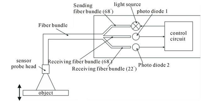
Figure 1. Reflectivity compensated fiber optical sensor.

Figure 2. “Statistically mixed” fiber arrangement in the sensor probe head.
The “statistically mixed” arrangement of the fibers provides for a uniform light and measurement spot and compensates for slightly inhomogeneities of the object’s surface. As a light source, a white light emitting diode was used to provide a broad band sending light. For the light detection, two equal silicon PIN photo diodes were employed as broad band receivers. The sensor system includes all necessary electronic circuitry for the analog and digital signal processing (i.e. transimpedance amplifiers, analog to digital converters, LED driver circuit, microcontroller, interface circuits, etc.).
3. Working Principle
3.1. System without Focus Lens
The numerical aperture NA of the fibers determines the opening angle α of the measurement light cone according to Equation (1).
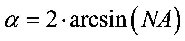 (1)
(1)
Furthermore, the opening angle influences the intensity curves of the two light receiving channels. Figure 3 shows the measured intensities of the two light receiving channels of the proposed sensor. The fibers of channel 1 and 2 have an opening angle of 22˚ and 68˚ respectively. The measurement was done for several objects with different reflectivity. Figure 3 exemplarily shows the curves for a gray and a bluish object.
As it can be seen, the corresponding curves are almost identical. Thus, the ratio of the intensities is an explicit measure of the object displacement. The intensity curves were recorded as a function of the object displacement d in the range of (1 to 6) mm using a triangulation sensor for the distance measurement. The normalization of the curves was done for a displacement of d = 1.6 mm. This displacement defines the nominal working distance of the sensor. At this displacement, the absolute intensity of channel 2 is decreased by approximately 20% from its maximum (maximum is given at d = 1 mm). Clipping of the sensor signal in the range of (1 to 1.6) mm is thereby avoided. This normalization method is a tradeoff for enabling a maximum bidirectional displacement variation and a moderate intensity loss at the nominal working distance.
The sensitivity S of a receiving channel is given by the negative slope of the corresponding intensity curve according to Equation (2).
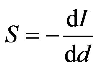 (2)
(2)
The sensitivity curves of the two sensor channels in the displacement range of (1 to 6) mm are illustrated in Figure 4. As it can be seen, the sensitivity curves for the
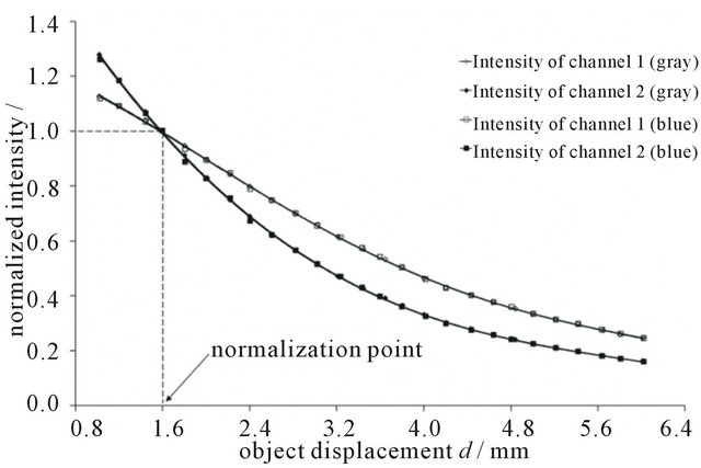
Figure 3. Normalized intensity curves vs. object displacement for different object reflectivities.
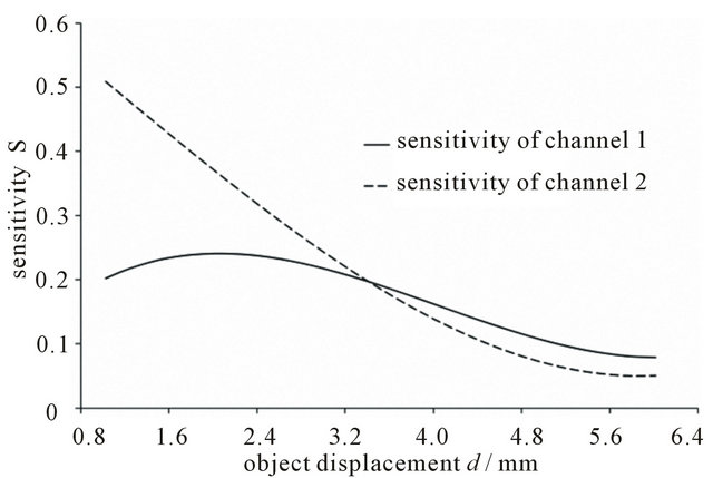
Figure 4. Sensitivity curves of the two sensor channels.
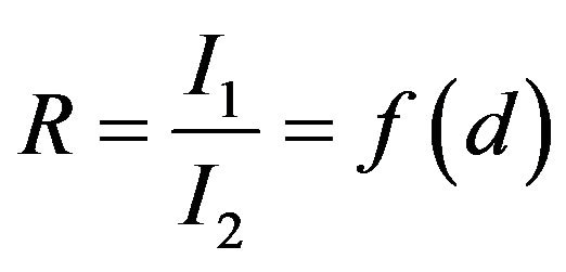
two channels are different. This is caused by the different opening angles of the used fibers for the two receiving channels. For such an arrangement, the ratio R of the intensity signals I1 and I2 of these two channels is a function of the displacement d of a reflective object (cf. Equation (3)).
 (3)
(3)
Because the sensitivity of a fiber optic displacement sensor is generally fairly independent from the surface reflectivity of the measurement object, the ratio R of the two intensity signals is independent from the reflective properties of the object too. The effect can be seen in Figure 5. The ratio R is shown in the range of (1 to 6) mm. The figure shows an almost linear range from (1 to 2.8) mm. But using a look-up-table (LUT) and a linear interpolation method, the non-linear range from approximately (2.8 to 6) mm may also be used to extend the working range. Alternatively to the LUT, a polynomial fitting function can be applied to linearize the sensor output.
3.2. System with Focus Lens
Figure 6 shows the arrangement with a focus lens. The lens is mounted on top of the sensor probe head and focuses the light of the fiber optics onto the object. By using a lens, the nominal working distance of the sensor can by extended significantly. For the used lens arrangement, the intensity curve of the sensor system has a distinctive maximum at 45 mm (cf. Figure 7).
In the proximity of the maximum, the sensitivity curves of the two receiving channels show a different trend. Thus, the ratio R of the two intensities again is a measure of the object displacement as described in the section above. Figure 8 depicts the two intensity curves and their ratio as a function of object displacement d in the range of (40 to 56) mm. In this figure, the ratio values are scaled for a better presentation.
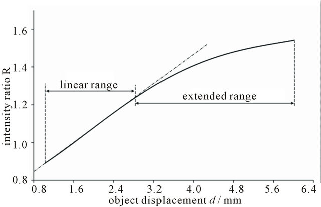
Figure 5. Intensity ratio vs. object displacement.
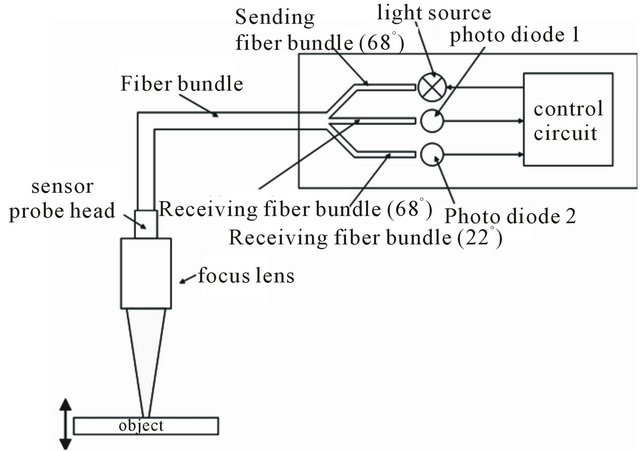
Figure 6. Sensor setup with mounted focus lens.

Figure 7. Normalized intensity vs. object displacement of the sensor with focus lens.
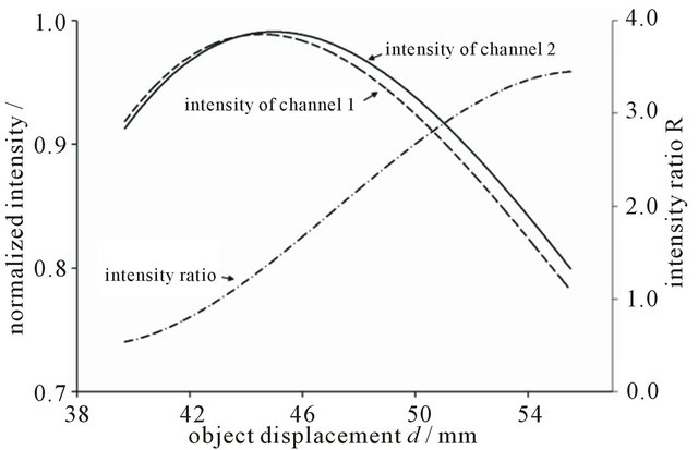
Figure 8. Normalized intensities and scaled intensity ratio vs. object displacement of the sensor with focus lens.
4. Conclusions
In comparison to the conventional methods, the proposed reflectivity compensation method for the fiber optic displacement sensor has several advantages. First, it is easy to implement and easy to handle. Due to the arrangement of the fibers in the sensor probe head, the light and measurement spot is homogeneous and well defined. The achievable measurement range of (1 to 6) mm is comparatively large and almost the half of the range is linear.
Second, by using a focus lens on top of the sensor probe head, the working range can be easily extended. This enables various applications with different object properties.
5. Acknowledgements
The authors would like to thank WINGS—Wismar International Graduation Services GmbH for support.
REFERENCES
- W. E. Frank, “Detection and Measurement Device Having a Small Flexible Fiber Transmission Line,” US Patent No. 3273447, 1966.
- C. D. Kissinger, “Fiber Optic Proximity Probe,” US Patent No. 3327584, 1967.
- C. D. Kissinger, “Fiber Optic Proximity Instrument Having Automatic Surface Reflectivity Compensation,” US Patent No. 4247764, 1981.
- C. D. Kissinger and R. Dormann, “Reflectivity Compensating System for Fiber Optic Sensor Employing Dual Probes at a Fixed Gap Differential,” US Patent No. 4488813, 1984
- L. Hoogenboom, “Fiber Optic Proximity Sensors for Narrow Targets with Reflectivity Compensation,” US Patent No. 4701610, 1987.
- C. D. Kissinger, “Reflectivity Compensated Fiber Optic Sensor,” US Patent No. 4701611, 1987.
- R. Hafle, “Fiber Optic Probe Sensor for Measuring Target Displacement,” US Patent No. 5017772, 1991.
- F. Suganuma, A. Shimamoto and K. Tanaka, “Development of a Differential Optical-Fiber Displacement Sensor,” Applied Optics, Vol. 38, No. 7, 1999, pp. 1103-1109. doi:10.1364/AO.38.001103
- X. Li, K. Nakamura and S. Ueha, “Reflectivity and Illuminating Power Compensation for Optical Fibre Vibrometer,” Measurement Science and Technology, Vol. 15, No. 9, 2004, pp. 1773-1778. doi:10.1088/0957-0233/15/9/014
- M. L. Casalicchio, G. Perrone, D. Tosi, A. Vallan and A. Neri, “Non-Contact Low-Cost Fiber Distance Sensor with Compensation of Target Reflectivity,” IEEE International Instrumentation and Measurement Technology Conference, Singapore, 5-7 May 2009, pp. 1671-1675. doi:10.1109/IMTC.2009.5168724
- A. Wego and G. Geske, “Reflexionskompensierter Faser- optischer Abstandssensor,” Photonik, Vol. 17, No. 5, 2012, pp. 62-64.
NOTES
*Corresponding author.