Journal of Sensor Technology
Vol.2 No.4(2012), Article ID:25485,7 pages DOI:10.4236/jst.2012.24023
A High Dynamic Range GMI Current Sensor
Laboratoire de Génie Electrique de Grenoble (G2E-Lab), Institut Polytechnique de Grenoble, ENSE3, Saint Martin d’Hères, France
Email: Aktham.Asfour@g2elab.grenoble-inp.fr
Received October 8, 2012; revised November 7, 2012; accepted December 6, 2012
Keywords: GMI; Current Sensor; Negative Feedback; DC-AC Current Measurements
ABSTRACT
The design and performances of a high dynamic range DC-AC current sensor utilizing Giant Magneto-Impedance (GMI) are presented. The sensor is based on a GMI element with negative feedback. The sensing element is a 30 µm diameter GMI Co-based amorphous wire. It is curled to a toroidal core of 2 cm diameter. A bias magnetic field of about 650 A/m is applied to the GMI element to obtain an asymmetric GMI effect. A strong negative feedback is introduced to ensure linearity in a wide dynamic range. Analog conditioning electronics was fully developed. This includes a square wave oscillator based on an inverter trigger; a peak detector and a high gain amplifier with zero adjust. The GMI element is driven at a 3 MHz frequency and 5 mA peak-to-peak current. The closed-loop operations are investigated and the performances of the sensor are presented. DC current measurements are performed. The sensor exhibits good sensitivity and very good linearity, free from hysteresis, in a wide dynamic range of ±40 A. The sensitivity is about 0.24 V/A and the linearity error is about 0.02% of the full scale (FS). The hysteresis error is smaller than the measurement accuracy. AC current measurements using the developed sensor have also been successfully achieved. The sensor bandwidth in closed-loop was about 1.7 kHz.
1. Introduction
Giant Magneto-Impedance (GMI) is a large change of the AC impedance of some soft magnetic materials (such as amorphous wires or ribbons) when they are subjected to an external DC or low-frequency AC magnetic field [1]. Since its discovery in the early ninety [2,3], the GMI effect has continued to attract particular interest in the development of a new class of magnetic sensors for a wide palette of applications [4,5].
The simplified model of the phenomena attributes this GMI effect to the change in the skin (or penetration) depth of the high frequency current in the magnetic conductor upon application of external magnetic field. In the case of an amorphous magnetic wire, the skin depth d of a high frequency current of frequency f0 is given by (1)
 (1)
(1)
where s is the conductivity of the magnetic material, µ0 the permeability of the vacuum and µr the relative transverse magnetic permeability of the wire. The strong dependence of the transverse permeability on the applied external magnetic field is in the origin of the change in the penetration depth and consequently in the AC impedance of the magnetic conductor. Measuring this impedance change gives then a measurement of applied magnetic field.
While intensive works and a large number of publications in this area focus mainly on materials and on the design of high sensitivity magnetic-field sensors [6,7], there are relatively few papers that have deeply investigated the application aspects of this type of magnetic sensors to indirectly measure other physical quantities such as electrical current, linear or angular position, force, strain, etc. [4]. Actually, all these quantities could be, roughly speaking, “converted” into a magnetic field, which in turn could be measured by a GMI sensor. In these kinds of applications, high sensitivity of the magnetic sensor could sometimes not be an issue.
The underling idea of the present work is to evaluate the potential of a GMI sensor for DC and low frequency AC electrical current measurement. The main applications in this area should concern power systems and automotive applications. Further works should also investigate linear and angular position sensors based on the GMI effect.
The principle of current measurement using a GMI sensor is relatively simple: a current produces a magnetic field which can be measured by a GMI sensor. A palette of articles has actually reported designs and performances of basic GMI current sensors utilizing both amorphous wires and ribbons [8-10]. A GMI current sensor was also patented [11]. These works have addressed the simple principle of GMI-based current sensors. Indeed, the sensor output was, as expected, non linear (or at best linear in a small dynamic range of the measured current) due to the intrinsic and strong non linear dependence of the impedance on the applied magnetic field. Moreover, the current direction could generally not be determined since amorphous materials exhibit symmetric dependence on positive and negative magnetic fields.
To develop linear GMI sensor, odd GMI characteristics should firstly be obtained. This could be done by a variety of methods such as the use of intrinsically asymmetric GMI materials [12] or the use of an external bias magnetic field. This external biasing could be achieved by a permanent magnet, a DC or an AC bias current [13- 16]. In such a way, the direction of the measured current could be determined, but the linearity of the sensor is only good in a limited range of current values. This linearity could secondly be improved using the concept of the negative feedback [14,17-19]. A GMI magnetometer setup that uses a feedback was investigated for high sensitivity magnetic field measurements [20].
For the application of current sensing, only Zhan et al. [18] have proposed a GMI sensor based on amorphous ribbons excited with a sharp pulse current. They used also field biasing and feedback. The sensor response was linear in a relatively small dynamic range of ±1.5 A. Only DC current measurements were performed.
In this paper, we present the full design and development of a linear current sensor using amorphous wire with both field biasing and strong negative feedback. Unlike the work presented in [18], we show that the optimization of the sensor allows achieving a very good linearity and a quite reasonable sensibility in a high dynamic range of ±40 A for application in power systems. In this context, low frequency AC current measurements have also been successfully performed using the developed sensor. The global performances of the sensor are shown to be very good in a large dynamic range of the measured DC and AC currents.
Circuits were fully designed and the operation principles of the sensor in both openand closedloops are analyzed to help the reader in easily reproducing the design with a minimum development time.
2. Sensor Design and Performances
2.1. Sensor Circuit and GMI Characteristics
A typical GMI sensor should be composed of a GMI conductor (wire in our case). A high frequency (f0) current with constant amplitude is supplied to the conductor. When an external magnetic field is applied, the change in the impedance gives a change of the amplitude of the voltage developed across the conductor. In other words; the applied magnetic field modulates the amplitude the voltage. A demodulation circuit allows then obtaining a voltage which is proportional to the impedance change.
These principles have been implemented in our sensor, together with field biasing and feedback. All the required sensor electronics was fully developed.
Figures 1 and 2 show a simplified block diagram and a photo of the developed sensor The GMI element is a Co-rich commercial wire (from Unitika Ltd.) of about 6.3 cm length and 30 µm diameter. This wire was curled to a toroidal core of a diameter d = 2 cm. A 25-turns bias coil and a 70-turns feedback coil are wound around the core (Figures 1 and 2). The measured current is Im.
The electronics is mainly composed of an oscillator based on an inverter trigger (74HC14), a peak detector and a high gain amplifier with zero adjust.
In open-loop operation, the oscillator generates a square wave form with 3 MHz frequency, 10 ns rise time and

Figure 1. GMI current sensor. The sensor diameter is d = 2 cm. Im is the measured current.
zero DC component. The voltage is converted into a constant square waveform current (iac) of 5 mA peak-topeak through the resistor R, and supplied to the GMI element. A peak detector, formed by the diode D and the filter Rp-Cp, provides a DC component proportional to the amplitude of the voltage of the GMI element and consequently to its impedance. This DC voltage is supplied to the instrumentation amplifier (AD620). The zero adjust of the amplifier is performed through a potentiometer. A zero voltage in the output of the amplifier should correspond to a zero external magnetic field. The amplifier output is measured using a digital voltmeter.
Figure 3 shows the GMI characteristics of the wire when excited under the previous conditions. This figure represents the GMI ratio which is defined as the relative change of the wire impedance (Z) with the applied magnetic field (H). This ratio is expressed by (2)

 (2)
(2)
where Z(H) and Z(Hmax) are the impedances of the wire at a given external field (H) and at the maximum available field (Hmax), respectively. This GMI ratio has been obtained using the same setup by measuring, at constant current, the voltage change across the GMI wire. The frequency of the square waveform current was 3 MHz.
2.2. Sensor Biasing and Performances in Open-Loop
In our design, the asymmetric GMI characteristics are obtained using a DC bias current. About 1.6 amperes current are applied to the bias coil, resulting in a bias field of about 650 A/m (Figure 3). In this working point, the sensor output was measured as a function of the DC measured current Im in open-loop. Results are shown in Figure 4. A sensitivity of about 7 V/A is measured, and excellent linearity is obtained in the dynamic range of ±1.5 A.
The sensitivity could also be expressed in terms of the circumferential magnetic field Hm produced by the measured current Im. This field is given by (3)
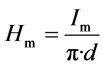 (3)
(3)
In this case, the open-loop sensitivity is easily calculated to be equal to 0.44 V∙m/A (35 V/Oe). This high open-loop gain (denoted A in the next sections) is necessary to ensure linear sensor response in closed-loop within a large dynamic range.
Notice that the sensitivity in open-loop strongly depends on gain of the amplifier and on the position of the bias point (working point) on the curve. This position is therefore of great importance and it could be chosen either on the increasing region of the curve (0 < H < 100

Figure 2. Photo of the developed sensor. Electronic circuits are not shown.
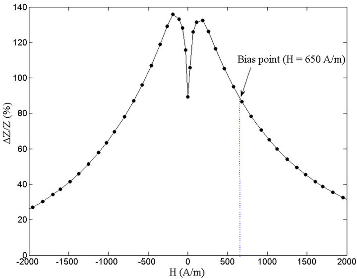
Figure 3. GMI characteristics of the amorphous wire.
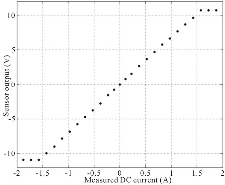
Figure 4. Sensor output versus measured current Im in open-loop. The sensitivity is about 7 V/A (or 0.44 V·m/A of the measured field Hm).
A/m) or on the decreasing part (H > 200 A/m). In our design, a position in the decreasing region was chosen for validation purposes only and without loss of generality. However, this position has to ensure some trade-off between linearity and sensitivity in open-loop.
On the other hand, one may notice that a bias current of 1.6 A is actually not realistic for industrial applications where power consumption is an important issue. In fact, this current could largely be reduced to a reasonable value by using a bias coil with more turns. Another alternative is to choice a bias point in the increasing part of the curve so as the bias field, and consequently the bias current could be dramatically reduced. This will be done in a new prototype which is currently being developed. Power consumption considerations will also be addressed in a future paper, together with the new prototype and other strategies for power consumption reduction.
2.3. Negative Feedback and DC-AC Current Measurements
A negative feedback circuit is introduced. The underlying idea is to improve the linearity in a wide dynamic range as well as to reduce hysteresis, instabilities of the open-loop and the temperature dependence of the GMI element.
The sensor output is therefore converted into a magnetic field, through the feedback resistor Rf and the feedback coil, and negatively fed-back to the GMI element (Figure 1).
Figure 5 shows the functional block diagram of the sensor system in closed-loop, where Hf is the magnetic field resulting from the feedback current. The transfer functions of the open-loop and of the feedback are denoted A and F, respectively.
Since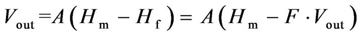 , it is straightforward to see that the transfer function of the system in closed-loop is given by (4)
 (4)
(4)
When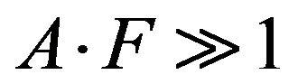 , then
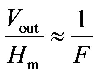 , and the output depends linearly on the measured magnetic field Hm (produced by the measured current Im)with a proportionality constant of
 .
.
In our design the transfer function of the feedback, F, is given by (5)
 (5)
(5)
where N is the number of turns of the feedback coil.
Since this constant depends only on the parameters of the feedback, the linearity of the sensor is expected to be

Figure 5. Block diagram of the closed-loop.
improved. Hysteresis, instabilities and temperature dependence errors should also be greatly reduced.
Figure 6 shows the sensor output versus the DC measured current Im, with N = 70 turns, d = 2 cm and two different values of the feedback resistor Rf (22 W and 44 W). For comparison purposes, the open-loop gain A was maintained unchanged.
These curves show a linear response. For Rf = 22 W, the sensitivity is of about 0.24 V/A within ±40 A dynamic range, while this same sensitivity is enhanced, as expected, to 0.46 V/A for Rf = 44 W in a dynamic range of ±25 A.
In both cases, the measured sensitivity was with good agreement with the theoretical prediction given by
 because
 .
.
The experimental results and the theoretical predictions are summarized in Table 1.
The linearity error was also quantified. For doing so, a linear fitting relation between the sensor output and the

Figure 6. Sensor output versus measured current in closedloop for two values of the feedback resistor.
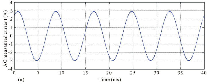

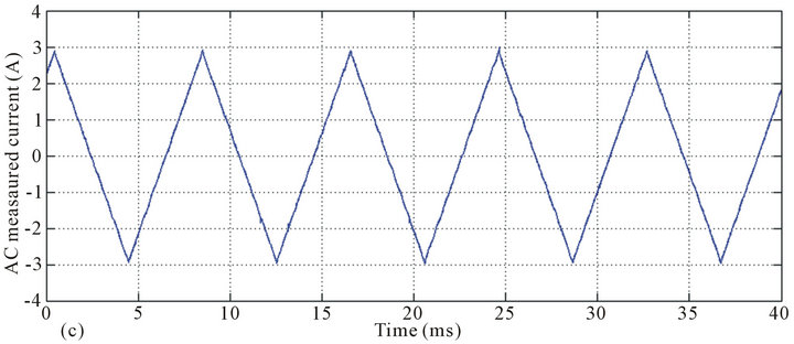

Figure 7. AC current measurements in closed-loop with a feedback resistor of 22 W. Waveforms from top to bottom: Sine current of 3 A amplitude and 50 Hz frequency (a) and the related sensor output (b); Triangular form AC current of 3 A amplitude and 50 Hz frequency (c) and the related sensor output (d).
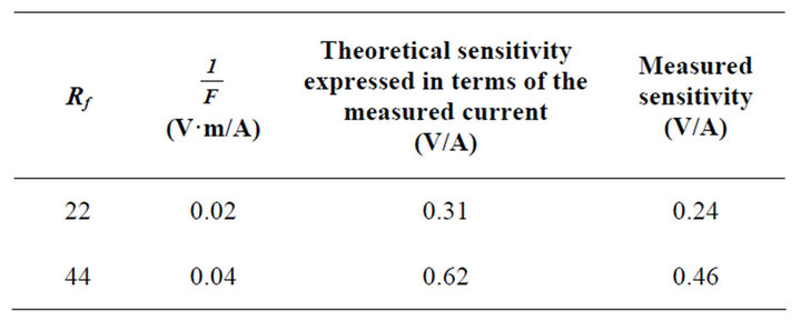
Table 1. Theoretical and experimental sensitivities in closedloop.
measured current is realized and the correlation coefficient α (α2 = 1 means perfect linearity) is obtained. We defined the linearity error e by (6)
 (6)
(6)
This error was about 0.03% of the full scale (FS) of ±25 A (Rf = 22 W) and 0.016% of the FS of ±40 A (Rf = 44 W).
All of these measurements were actually reliable.
Furthermore, the hysteresis error was smaller than the measurement accuracy. The well-known temperature dependence, which is the subject of our current work, is expected to be reduced by the use the negative feedback, since, once again, the gain in closed-loop is less dependent on the GMI characteristics than the open-loop gain.
AC current measurements were also performed using the developed sensor. The feedback resistor was fixed to 22 W. Results are shown in Figure 7, where both sine and triangular AC currents of 50 Hz frequency and 3 A amplitude are monitored. We can see that the sensor output accurately represents the form of the measured-current. In both cases, the peak value of the sensor output is about 0.72 V. This does mean that the sensitivity of the sensor of 0.24 V/A is retained for the AC currents.
Finally, the bandwidth of the sensor in closed-loop was measured to be about 1.7 kHz.
3. Conclusion
We have presented the development and performances of a GMI based current sensor with both bias field and negative feedback. The sensor could measure both DC and AC currents in a high dynamic range and within a reasonable bandwidth of 1.7 kHz. It exhibited good sensitivity and linearity. This may allow its use in power systems and other high current and large dynamic range measurement applications. This is why further studies should concern the temperature effect and its reduction, power consumption considerations as well as the test of the sensor in a real measurement environment.
REFERENCES
- H. Hauser, L. Kraus and P. Ripka,“Giant Magnetoimpedance Sensors,” IEEE Instrumentation and Measurement Magazine, Vol. 4, No. 2, 2001, pp. 28-32. doi:10.1109/5289.930983
- L. V. Panina and K. Mohri, “Magneto-Impedance Effect in Amorphous Wires,” Applied Physics Letters, Vol. 65, No. 9, 1994, pp.1189-1191. doi:10.1063/1.112104
- L. V. Panina, K. Mohri, T. Uchiyama and M. Noda, “Giant Magneto-Impedance in Co-Rich Amorphous Wires and Films,” IEEE Transactions on Magnetics, Vol. 31, No. 2, 1995, pp. 1249-1260. doi:10.1109/20.364815
- M. Phan and H. Peng, “Giant Magnetoimpedance Materials: Fundamentals and Applications,” Progress in Materials Science, Vol. 53, No. 2, 2008, pp. 323-420. doi:10.1016/j.pmatsci.2007.05.003
- H. Chiriac, M.Tibu, A. E. Moga, D. D. Herea, “Magnetic GMI sensor for detection of biomolecules”, J Magn. Magn. Mater., Vol. 293, 2005, pp. 671-676. doi:10.1016/j.jmmm.2005.02.043
- B. Dufay, S. Saez, Ch. P. Dolabdjian, A. Yelon and D. Ménard, “Impact of Electronic Conditioning on the Noise Performance of a Two-Port Network Giant Magneto Impedance Magnetometer,” IEEE Sensors Journal, Vol. 11, No. 6, 2011, pp. 1317-1324. doi:10.1109/JSEN.2010.2084996
- A. D. Bensalah, F. Alves, R. Barru´e, F. Simon and S. N. Kane1, “GMI Sensors Based on Stress-Annealed Iron Based Nanocrystalline Ribbons,” Sensors and Actuators A, Vol. 129, No. 1-2, 2006, pp. 142-145. doi:10.1016/j.sna.2005.11.030
- R. Valenzuela, J. J. Freijo, A. Salcedo, M. Vazquez and A. Hemando, “A Miniature dc Current Sensor Based on Magneto Impedance,” Journal of Applied Physics, Vol. 81, No. 8, 1997, pp. 4301-4303. doi:10.1063/1.364809
- T.-A. Óvári, H. Chiriac, C. S. Marinescu, F. J. Castaño, M. Vázquez and A. Hernando, “Magneto-Impedance Response in Ring Shaped Amorphous Wires,” Sensors and Actuators A: Physical Journal, Vol. 91, No. 1-2, 2001, pp. 207-209. doi:10.1016/S0924-4247(01)00468-X
- J. Pongsakoron and C. Sirisathitkul, “Low-Cost Sensors Based on the GMI Effect in Recycled Transformer Cores,” Sensors, Vol. 8, No. 3, 2008, pp. 1575-1584. doi:10.3390/s8031575
- D. J. Mapps and L. V. Panina, “Magnetic Field Detector and a Current Monitoring Device Including Such a Detector”, US Patent No. 2004/0075431 A1, 2004.
- Y. W. Rheem, C. G. Kim, C. O. Kim and S. S. Yoon, “Current Senor Application of Asymmetric Giant Magnetoimpedance in Amorphous Materials,” Sensors and Actuators A: Physical Journal, Vol. 106, No. 1-3, 2003, pp. 19-21.
- M. Malátek, P. Ripka and L. Kraus, “Double-Core GMI Current Sensor,” IEEE Transactions on Magnetics, Vol. 41, No. 10, 2005, pp. 3703-3705. doi:10.1109/TMAG.2005.854810
- P. Ripka, “Current Sensors Using Magnetic Materials,” Journal of Optoelectronics and Advanced Materials, Vol. 6, No. 2, 2004, pp. 587-592.
- B. Han, T. Zhang, K. Zhang, B. Yao, X. Yue, D. Huang, H. Ren and X. Tang, “Giant Magnetoimpedance Current Sensor with Array-Structure Double Probes,” IEEE Transactions on Magnetics, Vol. 44, No. 5, 2008, pp. 605-608. doi:10.1109/TMAG.2008.918789
- B. Han, T. Zhang, D. Huang, X. Yue, Y. Zhou and M. Bi, “Giant Magnetoimpedance Current Sensor with Spiral Structure Double-Probe,” IEEE Transactions on Magnetics, Vol. 45, No. 4, 2009, pp. 1999-2002. doi:10.1109/TMAG.2008.2010543
- K. Mohri, T. Uchiyama, L. P. Shen, C. M. Cai and L. V. Panina, “Amorphous Wire and CMOS IC-Based Sensitive Micro-Magnetic Sensors (MI Sensor and SI Sensor) for Intelligent Measurements and Controls,” Journal of Magnetism and Magnetic Materials, Vol. 249, No. 1-2, 2002, pp. 351-356. doi:10.1016/S0304-8853(02)00558-9
- Z. Zhan, L. Yaoming, C. Jin and X. Yunfeng, “Current Sensor Utilizing Giant Magneto-Impedance Effect in Amorphous Ribbon Toroidal Core and CMOS Inverter Multivibrator,” Sensors and Actuators A: Physical Journal, Vol. 137, No. 1, 2007, pp. 64-67. doi:10.1016/j.sna.2007.02.037
- S. S. Yoon, P. Kollu, D. Y. Kim, G. W. Kim, Y. Cha and C. Kim, “Magnetic Sensor System Using Asymmetric Giant Magnetoimpedance Head,” IEEE Transactions on Magnetics, Vol. 45, No. 6, 2009, pp. 2727-2729.
- A. Boukhenoufa, Ch. Dolabdjian and D. Robbes, “HighSensitivity Giant Magneto-Inductive Magnetometer Characterization Implemented with a Low-Frequency Magnetic Noise-Reduction Technique”, IEEE Sensors Journal, Vol. 5, No. 5, 2005, pp. 916-923. doi:10.1109/JSEN.2004.841451