Journal of Sensor Technology
Vol.1 No.3(2011), Article ID:7650,4 pages DOI:10.4236/jst.2011.13008
Precision Active Bridge Circuit for Measuring Incremental Resistance with ANN Compensation of Excitation Voltage Variation
Department of Electrical Engineering, Jamia Millia Islamia (A Central University), New Delhi, India
E-mail: khanshakeb@gmail.com
Received July 4, 2011; revised July 26, 2011; accepted August 20, 2011
Keywords: Active Bridge, Strain Gauge, ANN, Lead Resistance, Inverse Modeling
Abstract
The present work deals with the development of low cost, appreciably accurate precision electronic circuit for resistive sensor where measurement of the incremental resistance change with high degree of accuracy is essential. A linear and sensitive active half bridge circuit requiring only few components for its hardware implementation has been proposed for measuring very small resistance change due to change in physical quantity or chemical analytes. Theory of the proposed active bridge circuit has been discussed and experimental results have been compared with conventional bridge circuit. Initial measurements are made with Pt-100 Strain gauge sensor but it can be extended to other resistive sensors of practical importance. Results show that the active bridge circuit is almost four times more sensitive than conventional half bridge circuit and two times more sensitive than full Wheatstone bridge circuit. Studies have also been made to analyze the errors due to ambient temperature, connecting lead resistance and dc excitation voltage. Experimental results show that output of the circuit has negligible effect on ambient temperature and connecting lead resistance. The error due to excitation voltage has been compensated using Artificial Neural Network (ANN) based inverse modeling technique.
1. Introduction
Resistive sensors are some of the most widely used sensors because of low cost, easy to fabricate, and interface with signal conditioning circuits. Some of the common physical parameters where resistive sensors used widely are temperature, strain, pressure, light intensity, fluid flow or mass flow and humidity [1-4]. Metal oxide based sensors used for measuring environment polluting gases are also mostly based on resistive technique [4]. For measuring different physical and chemical parameters by resistive technique, the resistance value can vary from few fraction of ohm to several ohms to several hundred of ohms [2-3,5]. Measurement of resistance change of ohms to several hundred ohms is not much difficult but of small resistance change in presence of several non-ideal effects such as ambient temperature, electrical noise and OpAmp offset voltage may reduces the accuracy of measurement [3] significantly. Signal conditioning circuit involving resistive sensors should address the errors due to the nonlinearity associated with senor output [6], the effect of ambient temperature [7,8], fluctuation of the dc excitation voltage [8,9], non-ideal OpAmp offset voltage [10], connecting lead resistance [11-13] and noise signal [14].
Wheatstone bridge technique is one of the most widely used signal conditioning circuits for measuring small resistance change and it is still used for different industrial process parameters. Figure 1 shows the four commonly used bridge configurations suitable for sensor applications and the corresponding equations which relate the bridge output voltage to the excitation voltage and the bridge resistance values. In each of the configurations, Vs the excitation voltage, and R is the fixed value resistor in different arms chosen to be equal to the nominal value of the variable resistor(s). The deviation of the variable resistor(s) about the nominal value is proportional to the physical parameters to be measured, such as strain (in case of a strain gauge) or temperature (in case of resistance temperature detector).
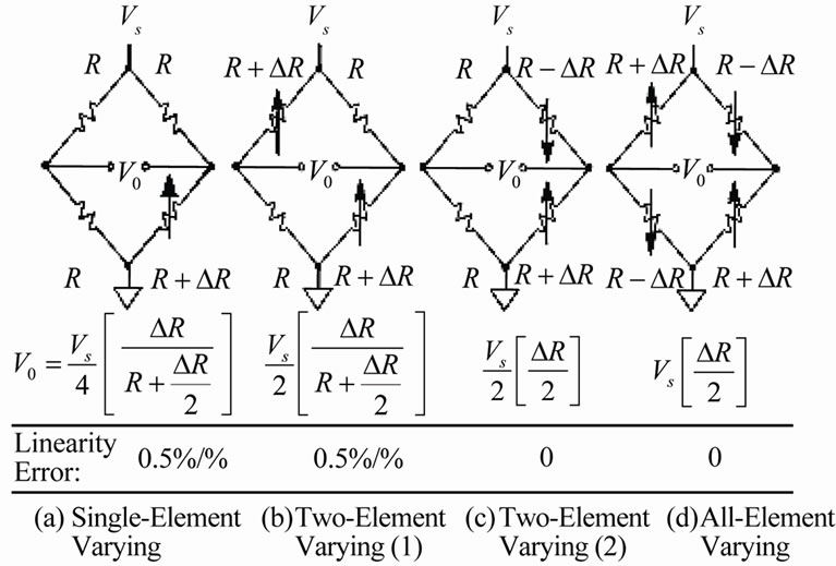
Figure 1. Different conventional bridge configurations [6].
Among the four different configurations, the all-element varying bridge (Figure 1(d)) produces maximum voltage output for a given resistance change and is inherently linear. Apart from linear output it has other advantages like, minimization of error due to self heating and the noise signal [7]. Major problem encountered in the bridge circuit is lower sensitivity due to very small change in resistance. Sensitivity can be improved by increasing the excitation voltage, which may results in power dissipation and the possibility of error due to sensor self heating. On the other hand, low value of excitation voltage requires more gain in the conditioning circuits which can increase error due to ambient temperature, non-ideal Op-Amp offset voltage and the sensitivity to noise [3].
In the recent past an active bridge useful for direct measurement of in-circuit resistances has been proposed [1]. This system is self-balanced, capable of measuring resistors even in a production line. However, the shunt resistances appearing across the unknown resistance affect the accuracy and start loading the Op-Amp. Also, if the resistance change is only a fraction of ohm, the circuit is less sensitive and effect of offset voltage of the OpAmp causes significant measurement error. However, to improve the sensitivity, it requires high excitation voltage or large gain of the amplifier or elimination of non-ideal OpAmp offset voltage.
In the present work, a linear and sensitive active half bridge circuit based on the Wheatstone bridge has been proposed for measuring incremental resistance change of resistive sensor where change in resistive value due to physical quantity is very small. The proposed circuit is basically modification of conventional half bridge circuit. The modified bridge circuit has improved the sensitivity, in comparison to conventional half and full bridge circuit, significantly. The theory of the proposed electronics has been discussed and experimental results have been compared with conventional circuits. Studies are also made to analyze the errors due to ambient temperature and connecting leads for remotely located strain gauge sensor. It is evident from the experimental result that the circuit compensates effects of ambient temperature and lead resistance of the considered resistive sensor. However, the effect of input excitation variation has direct impact in the accuracy of measurement. The error due to excitation voltage has been compensated by adopting normalization technique [14]. The normalization technique compensates error due to excitation voltage variation but it fails to provide full compensation. Further compensation is made using ANN based soft computing technique.
2. Working of the Electronics
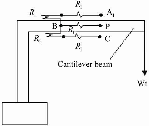
Figure 2(a) shows the schematic diagram of the experimental set up and Figure 2(b) shows the circuit diagram of the proposed measurement scheme [2]. It consists of a half active bridge circuit together with an inverting adder. One metallic strain gauge sensor with positive resistance change (R + ∆R) is placed on the top of the beam and the other with negative resistance change (R – ∆R) is placed on the bottom of the beam. The resistances R1 and R4 form the arms AB and CB of the proposed bridge circuit respectively.
In the arm AB, a buffer is employed to provide isolation from the adjacent arm AD and to generate two identical 180˚ out of phase signal at A1 and C respectively. For ac excitation voltage Vs, the signals at the outputs of the buffer and the inverting amplifier maintain 180˚
 (a)
(a)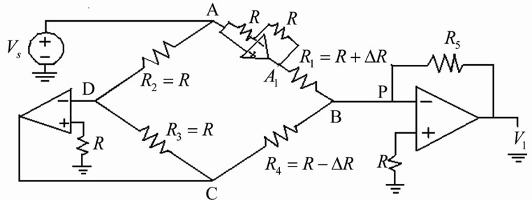 (b)
(b)
Figure 2. (a) Schematic diagram of strain gauge sensors on the cantilever; (b) Proposed active bridge circuit.
phase opposition over wide frequency which promotes measurement of ac conductivity of the sensor over large signal frequency [17].
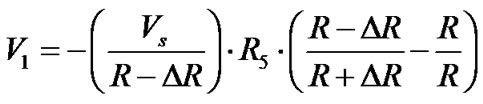
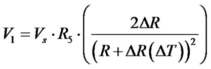
Application of Kirchhoff’s Current Law (KCL) at node B and with simplifications, the output voltage V1 is given by [2]
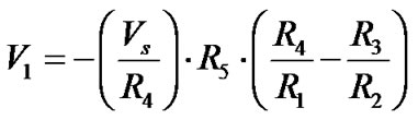 (1)
(1)
Replacing R4 by  and R1 by
 (2)
(2)
After simplification, Equation (2) can be written as
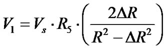 (3)
(3)
Since, incremental resistance, ∆R is a smaller quantity, typically, varies 0.1% to 0.5% over entire range with respect to the nominal value of sensor resistance R [5],
 and
and  (4)
(4)
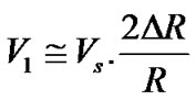
If the feedback resistance of the inverting adder amplifier is chosen to be equal to the nominal value of the sensor resistance, i.e. R5 = R, then Equation (4) can be written as
 (5)
(5)
The Equation (5) clearly shows that the sensitivity of the proposed bridge circuit is two times more than the conventional all-element varying bridge circuit of Figure 1(d) and 4 times more sensitive to two element varying bridge circuit of Figure 1(c).
Replacing change in resistance due to strain by [7]
 (6)
(6)
where,  is the gauge factor, R is the initial base resistance of the sensor and ε is the external strain, the voltage output of the detection circuit can be expressed as
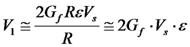 (7)
(7)
2.1. Effect of Ambient Temperature
To analyze the effect of the ambient temperature, let ∆R(∆T) is the change is resistance due to ambient temperature. Since the strain gauges are of metallic, ∆R(∆T) will increase with increase in temperature. The voltage output of the signal conditioning circuit including the temperature effect can be written as
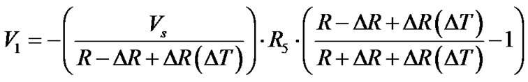
(8)
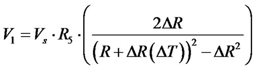 (9)
(9)

 (10)
(10)
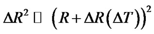
Again  and for R5 = R
 (11)
(11)
Thus due to differential form of the sensors arms in the active bridge circuit, the effect of ambient temperature is minimized.
2.2. Effect of Lead Resistance
Effects of lead resistance and its variation with ambient temperature is another source of error for resistive sensors particularly for metallic strain gauge [6-8,15]. Most of the techniques involve analog compensation where the effect of lead resistance is compensated by subtraction operation.
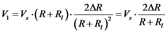
In the proposed circuit, to study the error due to lead resistance of the sensors, let Rl is the lead resistance of the sensors R1 and R4 respectively. The Equation (1) can be rewritten as
 (12)
(12)
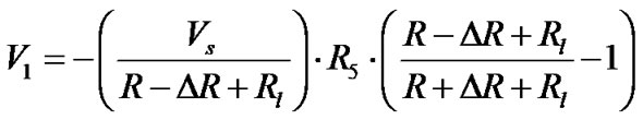 (13)
(13)
 (14)
(14)
 (15)
(15)
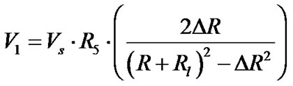
If  and additional metallic resistance of value Rl is added in series with R5, then Equation (15) can be written as
 (16)
(16)
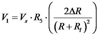
Considering  (a 100 ft copper wire can results the lead resistance of few ohms only [6]), Equation (16) can be further approximated
 (17)
(17)
Thus, voltage output of the signal conditioning circuit is directly related to the change in resistance of the sensor. However, additional lead resistance Rl between B and P shown in Figure 2(a) through which unbalanced detector current passes and converted into voltage signal by passing through a fixed metal film resistance. The lead resistance Rl is in series with the fixed resistance and its effect will be negligible.
2.3. Effect of Bridge Excitation Fluctuation
It is observed in Equation (17) that the input dc excitation voltage of the bridge circuit has direct influence on the sensor output. Very recently, artificial neural network (ANN) based soft compensator has been proposed for correcting the effect of the excitation voltage fluctuation for strain gauge resistive pressure sensor [13]. ANN based technique is appeared to be powerful technique for minimizing the errors for different types of the sensors [13]. The technique proposed in [13], the authors select the input voltage fluctuation of the order of 2 V or more which is impractical. Such wide variation of Vs hardly occurs in practice. Also if the deviation is significant its compensation is not much difficult. In practice, the excitation voltage fluctuates within small value randomly unless there is serious error in the supply of the excitation voltage. In the present work, error due to input voltage fluctuation of ±15% of the input reference voltage (in this case 1 V) which is often the practical situation has been compensated by using normalization technique. The normalization technique involves dividing the sensor output with the input excitation voltage of the bridge circuit. This method is simple to implement but not accurate. Attempt has been made to utilize the ANN technique to compensate the error due to excitation voltage.
3. Experimental Methods and Results
To compare the proposed active bridge circuit, the experiments have been conducted both with conventional as well as active bridge circuit using metallic strain gauges of nominal resistance 120 Ω. The resistance for the metallic strain gauge when force is applied can vary only from 0.1% to 0.5% of its nominal value. The experiments where carried over for the weights of 0 gm to 1000 gm in the division of 200 gm.
The full bridge circuit used conventionally as shown in Figure 3 was hardware implemented on a bread board. Four matched FET input OpAmp OP-07 which has very small offset voltage and noise along with metal film resistances have been used [8]. The resistance values were matched with a digital multimeter (Keithley Model 2000) and equal values resistances as shown in figure were selected. The excitation voltage to the bridge circuit is dc taken from precision voltage regulator (REF01) was fixed at 2 V.
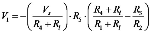
Here the voltage V1 is given as
 (18)
(18)
Also
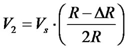 (19)
(19)
On applying both the voltage V1 and V2 into subtractor
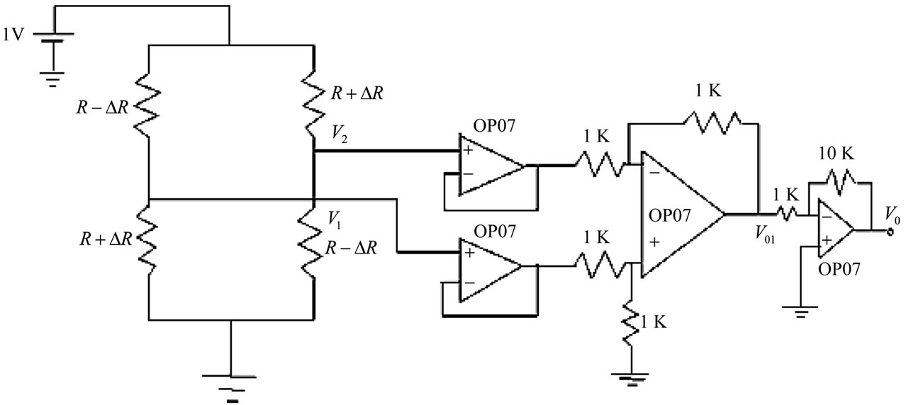
Figure 3. Conventional full bridge circuit used in experiments.
circuit with scaling factor of 10, the output voltage V01 is given as
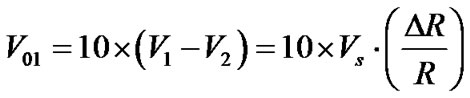 (20)
(20)
Figure 4 shows the actual response V0 of the circuit with the variation of the loads in gm. Voltage output of the circuit was noted for both increase and decrease in loads applied on the beam and average values of the output voltages are shown in figure. The response of the conditioning circuit with the variation of the load is linear. Experimental results for conventional half bridge circuit are also shown in Figure 4 (blue colour). It is observed that the response of the half bridge circuit is linear but its sensitivity with respect to full bridge circuit is almost half.
The sensitivity of the full bridge circuit is 0.015% while for half bridge circuit it is 0.08%. The sensitivity is defined as the percentage change in output voltage of the circuit to the reference voltage at zero loads to full scale applied loads.
To analyze the effectiveness of the active bridge circuit for increasing the sensitivity, the circuit shown in Figure 2(b) has been hardware implemented using an instrumentation type OpAmp like TLC-271. Experiments were conducted with the help of same experimental setup shown in Figure 2(a). The TLC271 provides extremely high input impedance of the order of TΩ and very low offset voltage [11]. The output voltage of the circuit was amplified by ten times as in case of Figure 3. The experimental results with the variation of applied loads in the range of 0 gm to 1000 gm are shown in Figure 4 (red colour). The sensitivity of the active bridge circuit is 0.027%. It is almost 4 times of the conventional bridge circuit and the variation is linear.
Further, experiment has been conducted by placing two strain gauges both having positive resistance change under strain in the ratio arm AB and CB. Since the ratio arms are in differential form, it is expected that with the increase in strain, the output of the circuit should remain
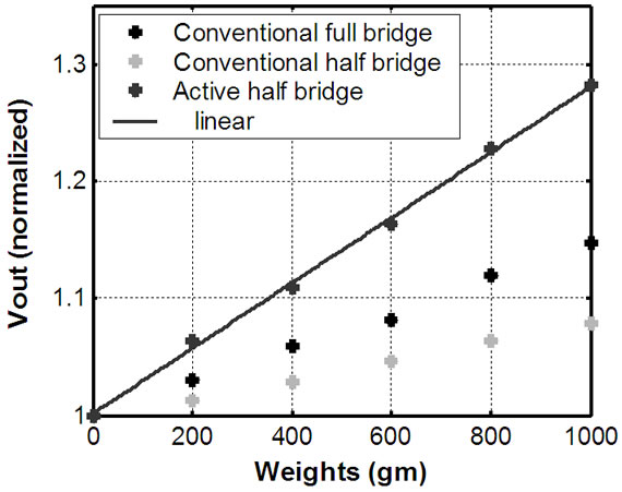
Figure 4. Voltage output of the bridge circuits with the variation of loads (Vi = 2.0 V, T = 30˚C).
unchanged. Figure 5 shows the experimental results. It is obvious in the figure that as the strain is increased from its initial value, the output remains almost unchanged.
4. Effect of Ambient Temperature
To analyze the effect of the ambient temperature, the gauge in arm RQ has been placed inside a controlled temperature oven. The ratio arm PQ has fixed value metal film resistance. The resistance of the arm PQ has been set to be as the resistance of the gauge in arm RQ. Temperature of the oven was varied from 30˚C to 70˚C. The change in output voltage of the circuit at different ambient temperature is shown graphically in Figure 6. It shows that the output voltage rises with increase in ambient temperature and the variation is almost linear. Further experiment was performed by replacing the arm RQ with another strain gauge and putting both the gauges inside the oven. Temperature of the oven was varied over the same range and the output voltage of the detection circuit was noted. Results indicate that the output change due to ambient temperature is significantly reduced. Small variation in the output can be attributed due to mismatch of the gauges.
Thus if the input excitation voltage of the bridge cir-
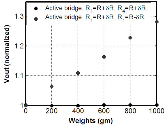
Figure 5. Response of the active bridge circuit for different resistance change of sensor arms (Vi = 2.0 V, T = 30˚C).
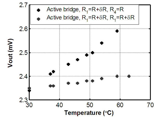
Figure 6. Effect of ambient temperature on the output of the signal conditioning circuit (Vi = 1.0 V).
cuit is assumed to be constant then, the output of the signal processing circuit depends only on the change in resistance of the gauges which in-turn depends on the strain. However, the output also depends on the excitation voltage.
5. Effect of Lead Resistance
As discussed in section 2.2 the lead resistance Rl between B and P of Figure 2(a) may introduce error when the sensors are located remotely. To analyze the effect of the lead resistance the circuit shown in Figure 2(b) has been modified and the modified form is shown in Figure 7 has been used. The resistance value of Rl is the metal film resistance varied from 0 to 20 Ω. The output of the signal conditioning circuit for different values of Rl is shown in Figure 8. The results show that drifts in output voltage upto 20 Ω is almost negligible.
6. Effect of Input Excitation Voltage of the Bridge Circuit and Its Compensation
Following two different techniques is used to compensate effect due to variation of excitation voltage.
6.1. Normalization Technique
To observe the effect of excitation voltage variation, the excitation voltage is varied by ±15% of its reference
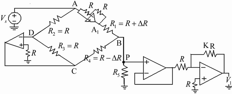
Figure 7. Modified form of the active bridge circuit.
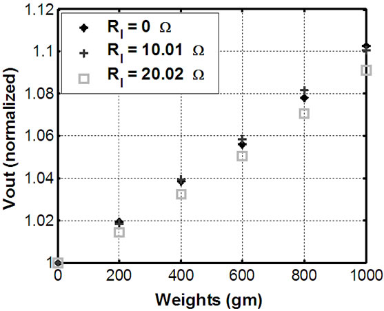
Figure 8. Variation of the output voltage of the active bridge circuit with lead resistance.
value (1 V) at constant room temperature of 30˚C both at loading and unloading condition of the cantilever. Figure 9 shows the output of the signal processing circuit for the variation of the excitation at different strain condition. It is shown in the plot that with the variation of the input excitation voltage, the output is linearly varied. Also as loading is increasing, the output also increases linearly. Figure 10 shows the relationship between the strain sensitivity and input excitation voltage. The sensitivity of the active bridge circuit which increases almost linearly can be expressed by linear equation obtained from fitting the plot as
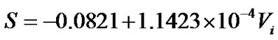
where S is the sensitivity in mV/gm and Vi is the excitation voltage in mV.
Since the output increases (or decreases) linearly with increase (or decrease) of input bridge voltage, if the output signal is divided by the excitation voltage, the effect
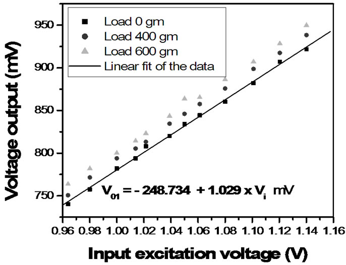
Figure 9. Variation of the output voltage with the variation of input voltage at different strain conditions (room temperature = 30˚C).
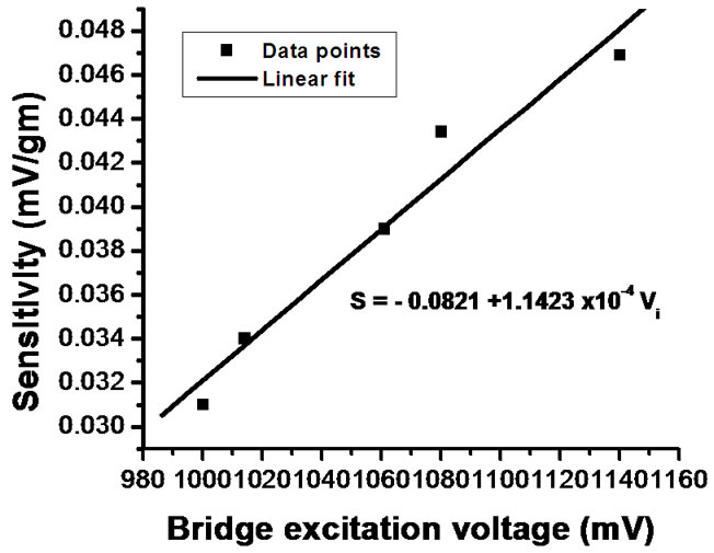
Figure 10. Effect of excitation voltage on the sensitivity of the strain resistive sensor.
of excitation will be minimized. Figure 11 shows the response of the signal processing circuit after normalization of the output voltage by the excitation voltage. For comparison, the actual output with excitation effect and the desired output without the effect of the excitation are also shown. Results show the error due to voltage fluctuation is reduced to 3% of original 18% value.
6.2. ANN Based Soft Compensator
To address the limitation of normalization technique, ANN based excitation voltage variation soft-compensation is proposed. Concept of ANN based inverse modelling has been utilized here [18]. The ANN based signal conditioning stage completely compensates the effect of excitation fluctuation and at the same times it gives estimated value of measurand as output. In this case, the output can be represented as a function of the applied strain (differential amplifier voltage) and the input excitation voltage Vi. Therefore, inputs to the proposed NN (neural network) are excitation voltage Vi and differential amplifier output Vo as illustrated in Figure 12.
Proposed network, for considered task, comprises two inputs, single output and one hidden layer. It has been found through simulation work that minimum number of hidden layer neurons required to achieve desired accuracy is 3. Network is implemented using MATLAB
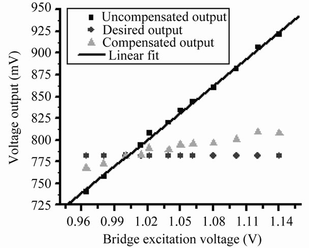
Figure 11. Voltage output after bridge excitation compensation.
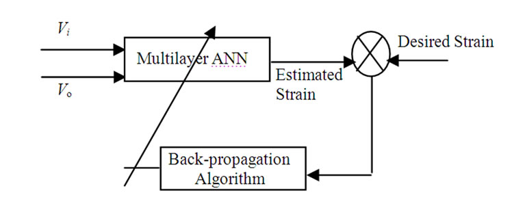
Figure 12. ANN based excitation voltage variation compensation.
ANN toolbox. The Levenberg-Marquardt algorithm is used to train the ANN. This algorithm is termed as the fastest method for training moderate-sized feed forward neural networks (up to several hundred weights). It also has a very efficient MATLAB implementation.
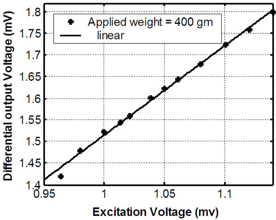
For training 8 data points are used covering entire considered excitation voltage variation range and for testing 12 data points are used, which comprises training data set as well as unforeseen testing data points. Network is trained for three different values of strain: 0 gm, 400 gm, and 600 gm. Figure 13(a) shows the actual deviation of the sensor output with the variation of the excitation voltage
 (a)
(a)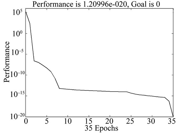 (b)
(b)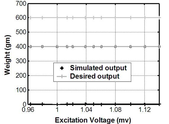 (c)
(c)
Figure 13. (a) Variation of the differential output of the signal conditioning circuit; (b) Mean squared error plot of the neural networjk training; (c) Simulation results of inverse modelfor compensating the effect of excitation volatge.
for a constant load of 400 gm. Figure 13(b) shows performance characteristic of the simulation work. It takes 35 epochs to achieve the minimum MSE (Mean Square Error) value of 6.09164 × 10⁻²⁴. The simulation results of the trained inverse model for excitation voltage compensation are shown in Figure 13(c).
From simulation results shown in Figure 13, it is evident that effect of bridge excitation voltage variation is completely compensated. This ANN stage output is measurand itself that is free from effect of excitation voltage variation and nonlinearity. Therefore, The ANN based data conditioning stage makes measurement completely insensitive to bridge excitation voltage variation.
7. Conclusions
The work reported in this paper is aimed at the development of linear and sensitive active bridge circuit with sensitivity larger than the conventional bridge circuit. Since the bridge output gives almost two times more voltage output than conventional bridge. The proposed circuit is simple to operate and requires only few components for its hardware implementation. It is capable of measuring incremental resistance change of both metallic and metal oxide based resistive sensor where the resistive value change due to physical quantity or chemical analytes is very small.
The circuit has been studied to observe the effect of lead resistance change, error due to ambient temperature variation, and fluctuation of the bridge excitation voltage. The theory of the signal processing circuit is well supported by the experimental results. The effect of the ambient temperature was also found to be negligible. The effect of excitation voltage variation has been compensated effectively using ANN based softcompensator. The future work involves online implementation of the softcompensator for displaying the measurand directly.
8. References
[1] M. Rehman and V. G. K. Murti, “A New Method for in-Circuit Resistance Measurement,” Journal of Physics E: Science and Instruments, Vol. 17, 1984, pp. 445-446. doi:10.1088/0022-3735/17/6/006
[2] M. Rehman, M. T. Ahmad and M. Arif, “Critical Study and Applications of a Self-Balancing Bridge,” IEE Proceedings, Vol. 137, No. A(1), 1990, pp. 23-26.
[3] Z. M. Rittersma, “Recent Advancements in Miniaturized Humidity Sensors―A Review of Transduction Techniques,” Sensors and Actuators A, Vol. 96, 2002, pp. 196-210. doi:10.1016/S0924-4247(01)00788-9
[4] Doeblin, “Measurement Systems Application and Design,” Tata McGraw Hill, Noida, 2002.
[5] Per Holmberg, “Automatic Balancing of ac Bridge Circuit for Capacitive Sensor Elements,” IEEE Transactions on Instrumentation and Measurement, Vol. 44, No. 3, 1995, pp. 803-805. doi:10.1109/19.387337
[6] J. Fraden, “Hand Book of Modern Sensors, Physics, Design and Applications,” 3rd Edition, New York, 2003.
[7] S. Poussier, H. Rabah and S. Weber, “Smart Adaptable Strain Gauge Conditioner: Hardware/Software Implementation,” IEEE Sensors Journal, Vol. 4, No. 2, 2003, pp. 252-267.
[8] A. J. Lopez-Martin, J. I. Osa, M. Ziza and A. Carlosena, “Analysis of a Negative Impedance Converter as a Temperature Compensator for Bridge Sensors,” IEEE Transactions on Instrumentation and Measurement, Vol. 52, No. 4, 2003, pp. 1068-1072. doi:10.1109/TIM.2003.814825
[9] A. P. Singh, S. Kumar and T. S. Kamal, “Virtual Compensator for Correcting the Disturbing Variable Effect in Transducers,” Sensors and Actuators A, Vol. 116, 2004, pp. 1-9. doi:10.1016/j.sna.2004.03.048
[10] G. A. L. Araujo, R. C. S. Freira, J. Silva, S. Y. C. Catunda and G. Fontgalland, “DC-Amplifier Input Offset Voltage Control in a Constant Temperature Thermo-Resistive Sensor Measurement Instrument,” IEEE Transactions on Instrumentation and Measurement, Vol. 56, No. 3, 2007, pp. 778-783. doi:10.1109/TIM.2007.894800
[11] T. K. Maiti, “Development of a Lead Resistance Compensation Technique for Remote Variable Resistive Sensors,” Measurement Science and Technology, Vol. 17, 2006, pp. 1424-1427. doi:10.1088/0957-0233/17/6/021
[12] T. K. Maiti and A. Kar, “A New Concept of Theory and Technique for Remote Strain Measurement,” Sensor & Transducer Journal, Vol. 77, No. 3, 2007, pp. 1045- 1050.
[13] K. F. Anderson, “The New Current Loop: An Instrumentation and Measurement Circuit Topology,” IEEE Transactions on Instrumentation and Measurement, Vol. 46, No. 5, 1997, pp. 1061-1067. doi:10.1109/19.676711
[14] E. Rubiola, C. Francese and A. De Marchi, “Long-Term Behavior of Operational Amplifiers,” IEEE Transactions on Instrumentation and Measurement, Vol. 5, No. 1, 2001, pp. 89-93. doi:10.1109/19.903883
[15] S. Pradhan and S. Sen, “An Improved Lead Compensation Technique for Three-Wire Resistance Temperature Detectors,” IEEE Transactions on Instrumentation and Measurement, Vol. 48, No. 5, 1999, pp. 903-905. doi:10.1109/19.799644
[16] D. H. J. Baert, “Circuit for the Generation of Balanced Output Signals,” IEEE Transactions on Instrumentation and Measurement, Vol. 6, 1999, pp. 108-110.
[17] T. Islam and H. Saha, “Study of Long-Term Drift of a Porous Silicon Humidity Sensor and Its Compensation Using ANN Technique,” Sensors and Actuators A: Physical, Vol. 133, No. 2, 2007, pp. 472-479. doi:10.1016/j.sna.2006.03.019
[18] A. Khan Shakeb, D. T. Shahani and A. K. Agarwala, “Sensor Calibration and Compensation Using Artificial Neural Network,” Transaction of Instrumentation, System and Automation Society, Vol. 42, No. 3, 2003, pp. 337-352.