Advances in Internet of Things
Vol. 2 No. 4 (2012) , Article ID: 23699 , 4 pages DOI:10.4236/ait.2012.24010
Inkjet-Printed UHF RFID Tags on Renewable Materials
Department of Electronics, Rauma Research Unit,
Tampere University of Technology, Tampere, Finland
Email: juha.virtanen@tut.fi
Received August 6, 2012; revised September 15, 2012; accepted September 27, 2012
Keywords: Inkjet-Printing; Renewable Materials; RFID; UHF
ABSTRACT
Radio frequency identification (RFID) provides great potential for different Internet of Things (IOT) applications. In the future, material choices in these IOT devices will have a huge effect on the environment and thus use of renewable materials is a growing trend. In this paper, passive ultra high frequency (UHF) RFID tags were inkjet-printed directly on wood, paper, and cardboard substrates, and their performance was evaluated by measuring two key properties: threshold power and theoretical read range. According to our measurements, the tags on wood showed read ranges of 7 - 8 meters, the tags on cardboard exhibited read ranges of 4 - 7 meters, and the tags printed on paper showed read ranges of 2 - 7 meters through the global UHF RFID band. According to these results, the performance of these inkjet-printed UHF RFID tags is sufficient for many IOT devices and potential applications e.g. in construction and packaging industry.
1. Introduction
Internet of Things (IOT) is a conceptual vision to connect everyday things and all kinds of devices in order to create a ubiquitous computing world. It has a great potential e.g. in home automation, intelligent transportation, and healthcare [1,2]. In order to connect objects to large networks, a simple, cost-effective, and reliable technology is crucial. Radio frequency identification (RFID) is an important wireless technology that has wide variety of applications and provides unlimited potential for IOT. In the future, material choices in these IOT devices will have a huge effect on the environment. This is why the use of renewable, environmental-friendly materials, such as wood and paper, is a growing trend. In addition, many industries are interested in novel smart products and great potential lies especially in construction and packaging industry, where wood and cardboard are typical materials. This makes integration of electronics and renewable materials an interesting research area.
In this paper, passive ultra high frequency (UHF) RFID tags were inkjet-printed directly on wood, paper and cardboard substrates and their performance was evaluated by measuring two key properties: threshold power and theoretical read range.
2. Passive UHF RFID System
Passive UHF RFID systems, in Figure 1, operate around 860 MHz to 960 MHz frequency band [3]. A typical system consists of three main components: readers, reader antennas and tags, which are attached to objects that are tracked and identified. A reader unit contains a transceiver, that is used to communicate wirelessly with the tags, and either an USB or an Ethernet port to communicate with the end-application, e.g. a database. A tag contains two components, an antenna and an integrated circuit (IC). The IC consists of a rectifier, modulator and non-volatile memory banks. The memory stores an electronic product code (EPC) that is the electronic fingerprint, a unique 96-bit long identification code [4-6].
The operation of passive UHF RFID systems is based on the coupling of electromagnetic waves. The reader unit generates a high frequency signal that is transformed into a wireless electromagnetic wave by the reader antenna. This signal is sent out for the tag antenna, which receives it and forwards it to the tag IC. Since passive tags do not contain any dedicated power supplies, e.g. batteries, the signal from the reader unit is used to provide operation power for the IC. Once the IC has rectified enough power to activate itself, the IC enables its modulator that switches between two loads in its input, a matched load and a non-matched load to generate a backscattered response containing the tag’s EPC.
3. Considerations for Woodand Paper-Based RFID Tag Substrates
The substrate material affects the tag performance through its electrical properties such as loss tangent and relative permittivity. The relative permittivity describes the amount of energy stored by the medium when an
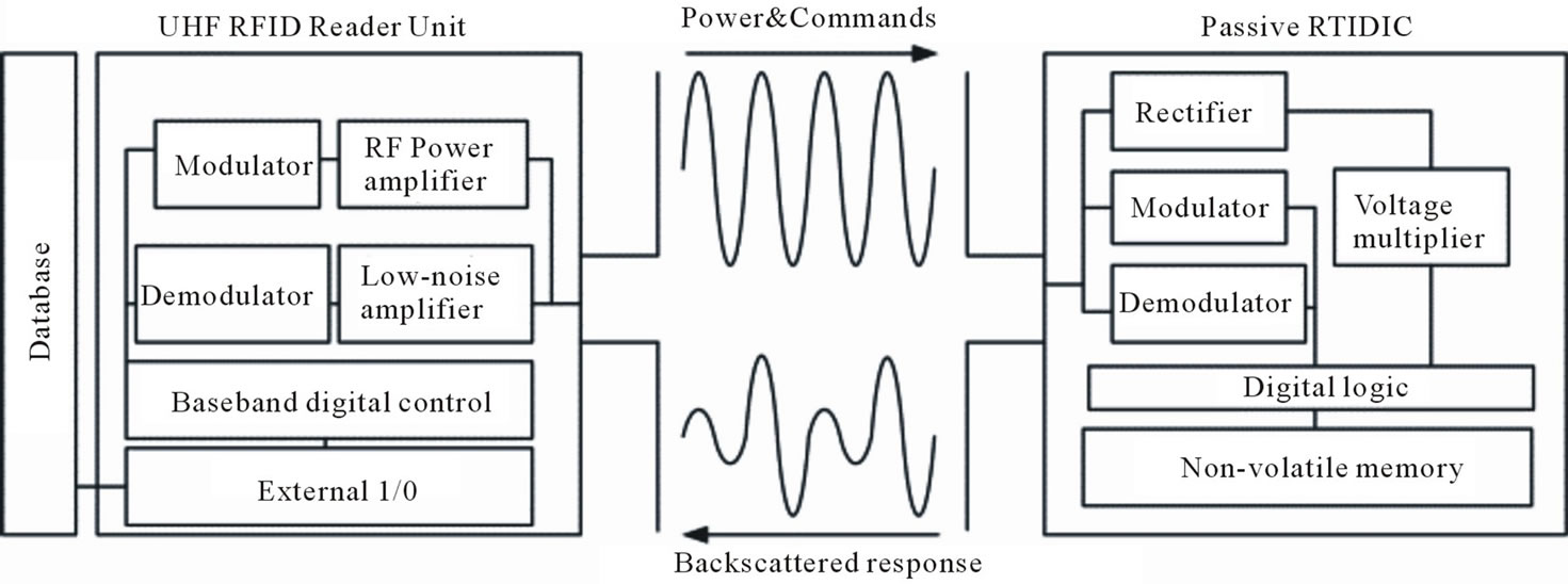
Figure 1. Passive UHF RFID system.
external electric field is applied. The loss tangent is quantity which is used to describe the losses in the dielectric material. The loss tangent is a measure of the conversion of the reactive power to the real power, dissipated as heat. Porous substrates also have an indirect effect on the tag through the ink film morphology, which depends on the printing method, substrate, and composition of the ink. On porous substrates, the ink can be partially absorbed into the substrate and the average thickness of the printed film depends thus on the substrate material. The cross-section area of the conductive film is an important parameter that affects the electrical performance of films printed with conductive inks. Both surface profile and thickness of the film have an effect on the cross-section area, and thus the substrate affects the ink film’s electrical performance. The loading effects of the materials surrounding the antenna need to be taken into consideration if high read ranges are desirable from a tag antenna in a given environment or on a given substrate material. Any materials, dielectric or metal, in the vicinity of the tag antenna will load the antenna causing changes in the input impedance as well as in the electrical length of the antenna. If such effects are not considered at the design stage of the antenna, the operation frequency is shifted and read range degraded. The dielectric properties, especially the loss tangent are closely related to the molecular structure of materials. The smaller the dipole moment (or polarity), the smaller is the value of the loss tangent of the material [7-10].
Some values for relative permittivity and loss tangent for paper reported in publications [11-13] are introduced in Table 1. In our case, the most relevant measured values for paper substrate are the ones reported in article [11] where the dielectric characteristics of paper were investigated in the UHF range. The relative permittivity and loss tangent of commercial paper were studied by using the microstrip ring resonator. It should also be noted that the reported values are not constant and they will vary with frequency, temperature, and humidity [12,14-19].
The relative permittivity of a 1.8 cm thick birch plywood slab was measured using an Agilent 85070E dielectric probe kit from 0.5 GHz to 3 GHz (Figure 2). The temperature of the slab was measured to be 23˚C and the moisture content was found to be 12% wt using a material moisture meter. The acquired relative permittivity of 2.5 at the global UHF RFID band (860 MHz to 960 MHz) and loss tangent are in good agreement with results for birch/beech type woods found in various related publications. However, the dielectric constant and loss tangent of wood are also highly dependent from the water content and temperature.
4. Design Considerations for Inkjet-Printing on Woodand Paper-Based Surfaces
Wood and paper-based surfaces are challenging for inkjet-printing due to their porosity and high surface roughness. The ink droplets are easily absorbed by the wood and paper, preventing the nanoscale metallization particles, which are contained within by the ink, to form a conductive layer. Paper and especially wood are also relatively new materials in the electronics industry and the electrical properties of various different paper and wood qualities are not yet extensively defined especially at different frequencies. This is why printing RF applications on wood, cardboard, and paper requires extra work to achieve suitable performance.
A unique characteristic of wood surfaces are their grain. A close-up examination of the grain reveals that the surface has grooves that vary according to the grain. In the direction of the grain such variations in the surface roughness are relatively low, whereas against the grain variations in the surface roughness are significant. Therefore, to maximize the performance and fabrication process throughput, the tag antennas should be printed in the direction and against the grain to properly fill the grain with conductive material. In fact, tag antennas
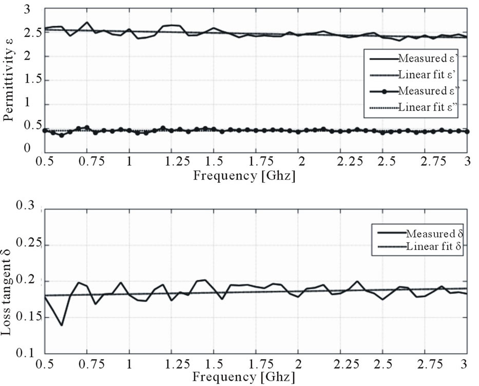
Figure 2. Dielectric properties of the birch based plywood, 23˚C and 12% wt.
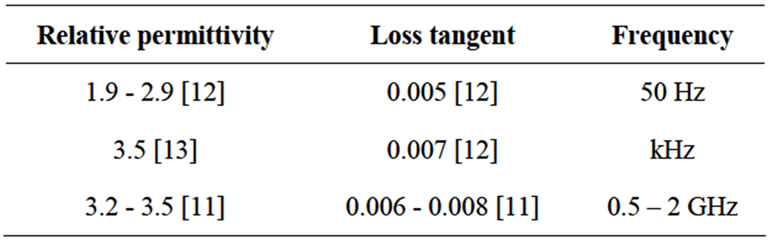
Table 1. Electrical properties of paper materials.
printed only in one direction did not function even with several layers on ink.
Our preliminary tests showed that tag antennas which were printed on wood along the grain showed the best performance, i.e. dipole was in line with the grain. Tag antennas printed on wood should be therefore designed so that most of the surface area in the antenna is located on one axis, to the direction of the grain. The one axis design rule has been one of the main design aspects in the tag antenna presented in this paper. The spread of the ink on wood, cardboard, and paper surface is also a major concern. In addition, on wood surface, the ink spread is highest in the direction of the grain. Therefore, tag antenna designs should be optimized so that there are no narrow gaps in the direction of the grain as the ink spread can cause short circuits in these areas. The amount of ink spread is related to the size of the grain as well as on the printing resolution, which should be kept as low as possible.
5. Tag Fabrication Process
5.1. Tag Antenna Design
The tag antenna design to be printed on renewable materials was designed to exhibit wide operating bandwidthreferred as wide band tag antenna, while obeying the one axis rule. Tag layout shown in Figure 3 and key dimensions listed in Table 2. The wide operating bandwidth was achieved by using an inductive loop type impedance matching network that provides the complex-conjugate matching [20]. The antenna is originally designed especially for wood substrate.
5.2. Key Parameters of the Inkjet-Printing Process
Samples for all three substrates were inkjet-printed using a Dimatix DMP-2800 material printer [21] equipped with 10 pl print head nozzles. Harima NPS-JL [22], a silver nanoparticle ink, was used as the conductive ink. The key parameters are listed in Table 3.
NPS-JL is especially suitable for renewable materials fabrication process as it requires low sintering temperatures, 120˚C minimum. Sintering is required for the nanoparticles to adhere to each other thus forming a conductive layer. The resistivity of NPS-JL is dependent on the sintering temperature and ranges from 4 - 6 µΩ·cm, this is approximately three times higher than the resistivity of bulk silver.
5.3. Printing and Curing of the Tags
The substrate materials used in this research were birch veneer, normal packaging cardboard, and silk surface art paper (Figure 4).
When printing on wood veneer substrate, the tag antennas were first printed in the direction of the grain using five layers of ink. In the second stage, the tag antennas were rotated 90 degrees counter-clock wise and five
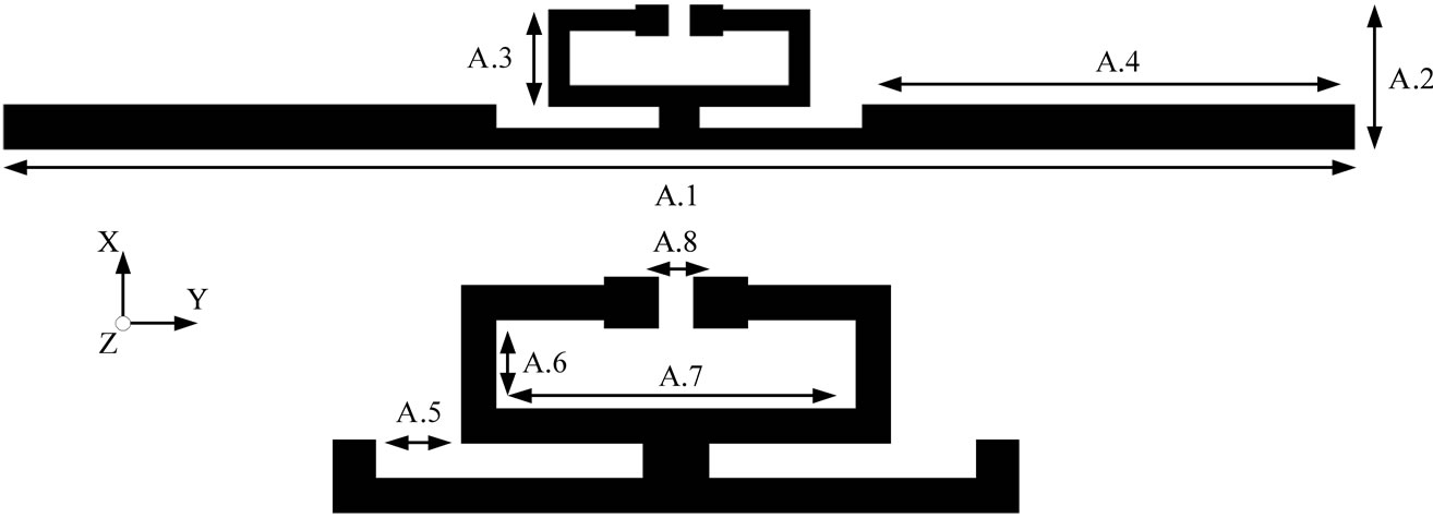
Figure 3. The wide band tag antenna design.
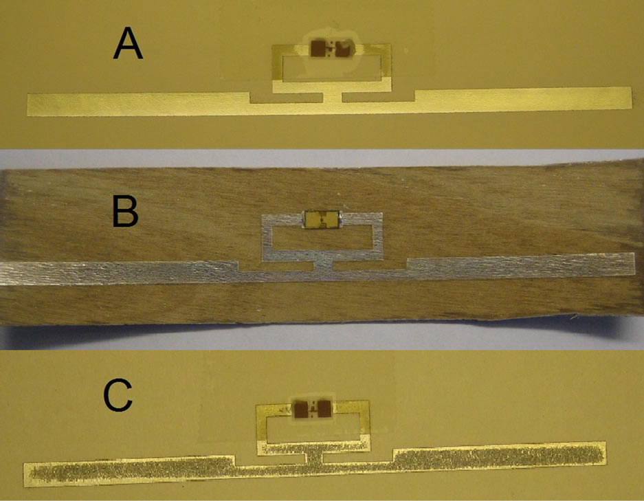
Figure 4. Inkjet-printed tags with ICs on (A) paper; (B) wood; and (C) cardboard.
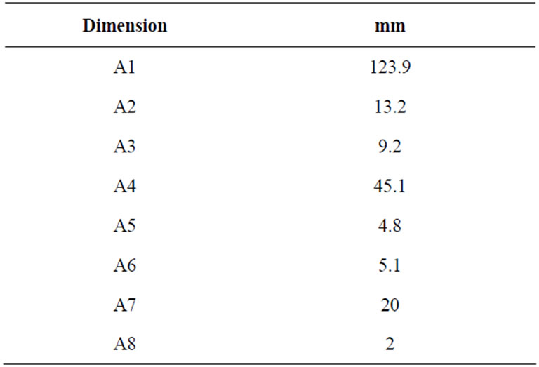
Table 2. The key dimensions of the tag antenna.
more ink layers were added against the grain. This ensures that the wood grain is fully filled with ink. It was found that without the second stage, samples printed on pure wood were not working, not even with ten layers of

Table 3. Key parameters of the inkjet-printing process.
ink printed in the direction of the grain. After the second stage, samples were sintered at 150˚C for 60 minutes. After sintering, the above mentioned process was repeated a second time. This was made to ensure sufficient conductor thickness for the antennas. In the case of printing tags on cardboard substrate, all layers were printed to same direction. There were two kinds of tags printed on cardboard; tags with twenty layers of ink and subsequent sintering and tags with ten layers of ink and subsequent sintering, repeated two times. The tags were sintered at 150˚C for 60 minutes. The tags printed on paper were manufactured by printing 15 layers of ink to same direction and then sintering at 150˚C for 60 minutes. Manufacturing parameters of all printed tags can be seen in Table 4.
After printing and curing, Higgs-3 RFID ICs (tags printed on wood) and NXP RFID ICs (tags printed on paper and cardboard) were attached to the samples using a conductive silver epoxy resin. It should be noted that the antenna was originally designed for Higgs-3 IC. Both of these IC’ have the sensitivity of ~18 dBm but the input impedance is different, which may cause differences in results. Figure 4 shows a picture taken from fully fabricated, inkjet-printed tags on paper, wood, and cardboard.
6. Evaluation of the Tags
6.1. Measurements
This section presents results from measurements that were performed to characterize the performance of the printed tags on different substrates. All of the measurements made for this study were performed using Tagformance, an RFID measurement unit. It was used to measure the key properties of passive UHF RFID tags: threshold power and theoretical read range.
Threshold power describes the minimum transmit power, at the transmit port, to activate the tag. Theoretical read range describes the maximal distance between the tag and reader antenna in free space, i.e. environment without reflections or external disturbances; hence the term theoretical read range. The measurement system is able to calculate the theoretical read range of a tag using its measured threshold power along with the measured forward losses. The forward loss, i.e. loss from the transmit port to the tag, is calculated using a reference tag. Furthermore, the system assumes that the read range is limited by the allowed transmitted power levels. The measurement system calculates the theoretical read range based on the measured path-loss and threshold power, i.e. transmit power level at the generator output required to activate the tag under test. This calculation is made according to the following equation
 (1)
(1)
where EIRP is the maximal allowed equivalent radiated power by the regulations (3.28 W in Europe), PTS is the threshold power of the tag under test and Lfwd is the measured path-loss in the forward link in the measurement setup.
6.2. Results and Discussion
The threshold power and theoretical read ranges of the samples were measured from 800 MHz to 1000 MHz in a compact anechoic chamber. The measurement unit was used in conjugation with a 6 dBi linear patch antenna. The measurement distance was 45 cm. According to our measurements, tags on both wood and cardboard substrates showed good performance throughout the global UHF RFID band. The tags printed on paper showed sufficient performance, but the performance changed significantly through the UHF RFID band. The threshold power and theoretical read ranges of tags printed on wood, paper and cardboard can be seen in Figure 5.
The optimum frequency for tags printed on wood seems to be between 880 - 940 MHz while the optimum frequency for tags printed on cardboard can be found between 900 - 960 MHz (20 layers) and 920 - 970 MHz (10 + 10 layers). The optimum frequency for tags printed on paper is around 980 MHz.
The tags printed on pure wood showed read ranges of 7 - 8 meters throughout the global UHF RFID band. These read ranges are long enough for many future IOT applications and for needs of packaging and construction industry. The tags printed on cardboard using directly 20 layers of ink and only one sintering showed read ranges of 5 - 6 meters and tags printed on cardboard by printing 10 + 10 layers showed read ranges of 4 - 7 meters through the UHF RFID band. Thus, also read ranges of tags printed on
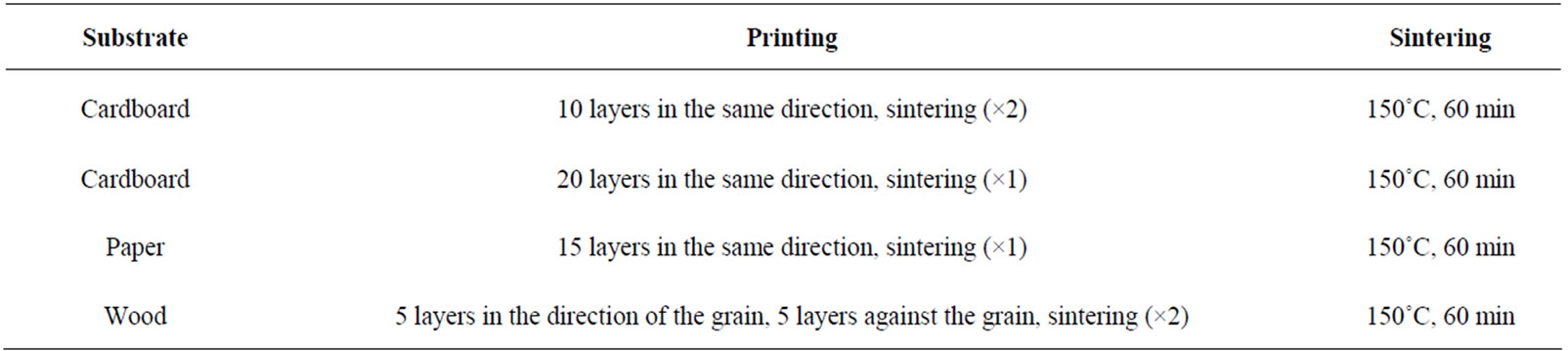
Table 4. Manufacturing parameters of all tags.
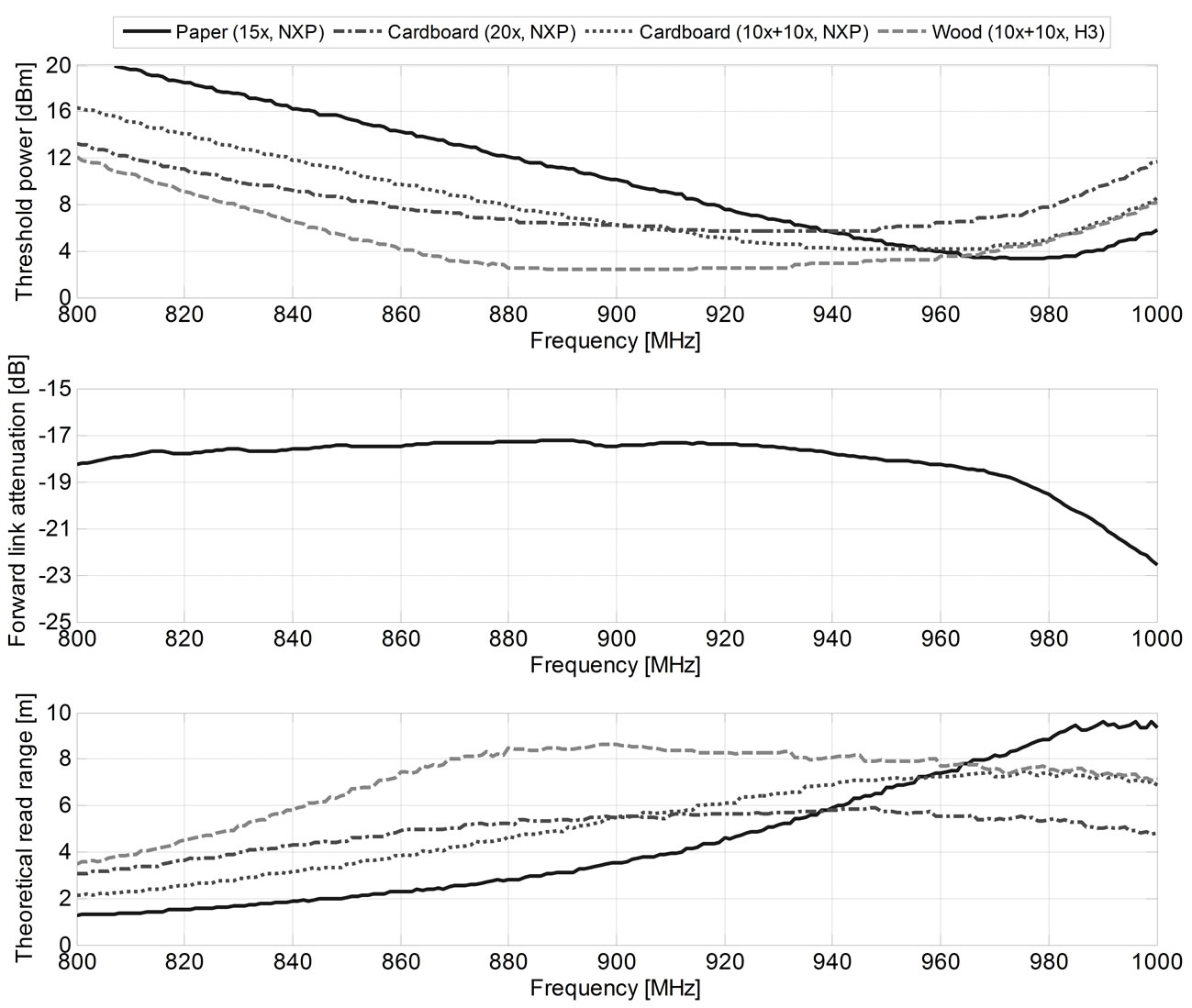
Figure 5. Performance of tags printed on paper, cardboard, and wood.
cardboard offer a great potential for many future applications. The read range of tags printed on paper changed between 2 - 7 meters through the UFH RFID band. More research is needed in order to find the right parameters for manufacturing. However, also these results are promising, especially considering that the antenna was originally designed for Higgs-3 IC and wood substrate.
7. Conclusion
The use of renewable, environmental-friendly materials, such as wood and paper-based materials as a substrate for electronics is an interesting research area, especially considering the material choices in many future devices. In this paper, passive UHF RFID tags were inkjet printed on wood, paper, and cardboard. According to our measurements, the tags on wood showed read ranges of 7 - 8 meters, the tags on cardboard exhibited read ranges of 4 - 7 meters, and the tags printed on paper showed read ranges of 2 - 7 meters through the global UHF RFID band. According to these results, the performance of these inkjet printed UHF RFID tags is sufficient for many real life devices and potential applications e.g. in construction and packaging industry. Next step is to optimize the amount of used ink.
8. Acknowledgements
This research work has been funded by Finnish Funding Agency for Technology and Innovation (TEKES), Academy of Finland, Centennial Foundation of Finnish Technology Industries, and Finnish Forest Foundation.
REFERENCES
- Commission of the European Communities, “Internet of Things—An Action Plan for Europe,” 2009. http://ec.europa.eu/information_society/policy/rfid/documents/commiot2009.pdf
- R. van Kranenburg, “Internet of Things Europe,” Conference Report, 2010. http://ec.europa.eu/information_society/policy/rfid/documents/iotconferencereport2010.pdf
- GS1, “Regulatory Status for Using RFID in the UHF Spectrum,” 2012. http://www.gs1.org/docs/epcglobal/UHF_Regulations.pdf
- M. Dobkin, “The RF in RFID,” Wiley, New York, 2010.
- K. Finkenzeller, “RFID Handbook: Fundamentals and Applications in Contactless Smart Cards, Radio Frequency Identification and Near Field Communication,” Wiley, New York, 2010. doi:10.1002/9780470665121
- GS1, “EPC Class-1 Generation-2 UHF RFID Protocol for Communications at 860 MHz to 960 MHz,” 2012. http://www.gs1.org/gsmp/kc/epcglobal/uhfc1g2/uhfc1g2_1_2_0-standard-20080511.pdf
- S. Merilampi, T. Björninen, A. Vuorimäki, L. Ukkonen, P. Ruuskanen and L. Sydänheimo, “The Effect of Conductive Ink Layer Thickness on the Functioning of Printed UHF RFID Antennas,” RFID—A Unique Radio Innovation for the 21st Century, Vol. 98, No. 9, 2010, pp. 1610-1619.
- T. Björninen, S. Merilampi, L. Ukkonen, P. Ruuskanen and L. Sydänheimo, “A Performance Comparison of Silver Ink and Copper Conductors for Microwave Applications,” IET Microwaves, Antennas & Propagation, Vol. 4, No. 9, 2010, pp. 1224-1231. doi:10.1049/iet-map.2009.0241
- S. Merilampi, T. Björninen, L. Ukkonen, P. Ruuskanen and L. Sydänheimo, “Characterization of UHF RFID Tags Fabricated Directly on Convex Surfaces by Pad Printing,” The International Journal of Advanced Manufacturing Technology, Vol. 53, No. 5, 2011, pp. 577-591. doi:10.1007/s00170-010-2869-y
- G. Shaker, S. Safavi-Naeini and M. M. Tentzeris, “Inkjet Printing of Ultrawideband (UWB) Antennas on PaperBased Substrates,” IEEE Antennas and Wireless Propagation Letters, Vol. 10, 2011, pp. 111-114. doi:10.1109/LAWP.2011.2106754
- L. Yang, A. Rida, R. Vyas and M. M. Tentzeris, “RFID Tag and RF Structures on a Paper Substrate Using Inkjet-Printing Technology,” IEEE Transactions on Microwave Theory and Techniques, Vol. 55, No. 12, 2007, pp. 2894-2901. doi:10.1109/TMTT.2007.909886
- M. A Laughton and D. F. Warne, Eds., “Electrical Engineer’s Reference Book,” Elsevier, New York, 2003.
- J. Fraden, “Handbook of Modern Sensors—Physics, Designs and Applications,” Springer-Verlag, Berlin, 2004.
- D. K. Cheng, “Fundamentals of Engineering Electromagnetics,” Addison-Wesley, New York, 1993.
- M. Prudenziati, Ed., “Thick Film Sensors,” Elsevier, New York, 1994.
- K. H. J. Buschow, R. W. Cahn, M. C. Flemings, B. Ilschner, E. J. Kramer and S. Mahajan, Eds., “Encyclopedia of Materials—Science and Technology,” Vol. 1-11, Elsevier, New York, 2001.
- C. F. Coombs, “Coombs’ Printed Circuits Handbook,” McGraw-Hill Publishing, New York, 2001.
- Forest Products Laboratory US Department of Agriculture, “Wood Handbook—Wood as an Engineering Material,” 2001.
- E. A. Campo, “Selection of Polymeric Materials—How to Select Design Properties from Different Standard,” William Andrew Publishing/Plastics Design Library, Norwich, 2008.
- G. Marrocco, “The Art of UHF RFID Antenna Design: Impedance-Matching and Size-Reduction Techniques,” IEEE Antennas and Propagation Magazine, Vol. 50, No. 1, 2008, pp. 66-79. doi:10.1109/MAP.2008.4494504
- Fujifilm, “Dimatix Materials Printer DMP-2800,” Product Overview, 2012. http://www.fujifilm.us/products/industrial_inkjet_printheads/deposition-products/dmp-2800/index.html
- Harima, “NPS-JL Silver Nanoparticle Ink,” NanoPaste Series, Metal Paste for Thin Film Formation, Datasheet, 2012. http://www.harima.co.jp/en/products/pdf/16-17e.pdf