Advances in Internet of Things
Vol.2 No.2(2012), Article ID:18631,10 pages DOI:10.4236/ait.2012.22003
Design and Implementation of a Low-Power Active RFID for Container Tracking at 2.4 GHz Frequency
Electrical Faculty, K. N. Toosi University of Technology, Tehran, Iran
Email: dawoodmoeinfar@gmail.com, shamsi@eetd.kntu.ac.ir, fnviolet@yahoo.com
Received November 22, 2011; revised December 28, 2011; accepted January 10, 2012
Keywords: Radio Frequency Identification (RFID); CC2530; RSSI; Active Tags; Collision; TDMA; IEEE 802.15.4; Sleep Mode
ABSTRACT
In this paper a new active RFID system at 2.45 GHz based on the low-power system-on-chip CC2530 RF transceiver is designed and implemented. Only by using of an integrated multi-channel fast chip, both the MCU and RF operations are done which makes the RFID more reliable and reduces the complexity of the hardware and cost, vividly. This RFID system utilizes the Zig-Bee IEEE 802.15.4 standard in the ISM band. A lot amount of energy is restored by setting Tags in the sleep mode in the most of times. The maximum transmission range of 80 m at the output power of 4.5 dBm is obtained. The main application of this system is for the container identification with precise operation and high accuracy. An active Tag with unique ID is mounted on each vehicle. By enabling the AUTOCRC error detection possibility, minor errors are detected in the received frames. Receiver sensitivity of –97 dBm and current consumption of 1 µA in the sleep mode and 29.6 mA in the active mode are reported.
1. Introduction
Radio Frequency Identification technology had been widespread in recent years, and encompasses an extensive range of wireless applications such as distribution, transportation, tracing, patient monitoring, military applications and etc. RFID is an automatic real-time non-contact identification technology that deals with Identification Numbers (ID) through scattered electromagnetic waves in the air. It’s more reliable, efficient, secured, inexpensive and accurate than other similar automatic identifiers such as sensor networks, imagery systems and so on. These reasons are why the RFID technology is more popular, recently [1].
An electronic label dedicates to each identifiable object, which contains main information or specification about that object. This label is named Tag and restores the data for a long time. Each Tag has a same structure and function. It consists of a microchip and antenna. Another key part of an RFID system is Reader (data collector), which collects the data stored in the Tags. A Reader includes the microprocessor, transceiver, antenna and a peripheral interface for user commands and monitoring. This two structured electronic devices which are at the heart of every RFID system, communicate with each other in the wireless manner [2]. Whenever a Tag is located at the magnetic zone of the Reader, it will be recognized by it, and afterward they enter to the relationship with each other according to the user request. Unlike some proposed RFID schemes, which have some Readers and Tags, our design is a centralized RFID with only a central Reader and numerous Tags. According to Figure 1, user interface (PC) is the main master of operation in RFID system. So, sub-master (Reader) commands Tags only by the request of the main master (PC). Tags only respond to the commands, whenever they have been investigated. Interrogated data from Tags are exhibited to the user with the serial interface.
One important classification in RFID is based on the method of power supply provision in Tags. Passive Tags don’t have any internal power source. They extract their energy from the Reader scattered wave and only act within the magnetic domain of the Reader. This type of
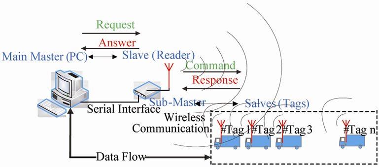
Figure 1. Centralized RFID system.
RFID is used for short-range applications such as smart cards. In addition to passive RFID Tags, active RFID Tags are designed having their own power supply, which is the basis of our work. They even act out the range of magnetic field of the Reader. RFIDs are designed at the standard frequency ranges: low-frequency (LF), highfrequency (HF), Ultra High Frequency (UHF) and Microwave. In the comparison of different types of RFIDs, lower frequencies don’t penetrate or transmit around metals, handle only small amounts of data and slow the data transfer. The main advantages of microwave frequencies are smaller size, smaller antenna and higher data range than other frequencies [3].
By emerging advanced technology and improving the economy, the automation of harbors is necessary. Using RFID, a large amount of time and cost will be restored and the safer transportation method is provided. Because containers occupy a large area at the ports, the RFID interrogate zone should be large enough to cover a wide range. So active Tags at the microwave frequency should be used for these applications [2,4].
Collision phenomenon is a common problem that we have encountered at the first step of designing a multiTag RFID system. Whenever several Tags are presented in the interrogate zone of Reader and respond to the Reader command simultaneously, their data collide in the air. So a lot amount of energy, bandwidth and time will be wasted. Different anti-collision procedures have been designed for avoiding from the collision. Because TDMA protocols are the largest applicable group of anti-collision, hence we focus on TDMA in this paper. [3].
Power consumption is always a remarkable criterion in the design of Tags, especially in the applications where power supply is limited. One drawback of the active RFID systems is the precise synchronization requirement between the Reader and Tags. In this work, we put Tags in the sleep mode most times, which all circuitry of Tags are turned off during the sleep mode. A Tag is only activated by the Reader command in the small fraction of one reading cycle. So, in the major portion of time, Tag is inactive.
This paper is organized as below: at first the hardware is described in detail. Second, software algorithm and anti-collision protocol are described, completely. After that, experimental results are reported. Finally, we conclude our work.
2. Hardware Description
Unlike other previous similar works, which use some modules to meet the requisite of a practical RFID system, our hardware uses only a low-power high-accuracy transceiver for both Reader and Tags [4,5]. It has all capabilities of a microprocessor and RF transceiver module in an integrated chip [6]. So, it handles all the baseband and RF processing functions together. In addition to minimize the hardware size, it prevents from high frequency noise generated from connecting RF transceiver and MCU chips. This integrated chip benefits from the low power consumption, high communication range, high capacity memories, multiple channels, and high sensitivity receiver [7]. Some critical issues in the active RFID should be considered when developing the hardware [8]. The first key point of the development is the lifetime of the active RFID Tag. Because the active RFID Tag is energized by the internal battery, the lifetime of the Tag is mainly depends on the lifetime of the battery. At first, we choose the low-power components and implement a mechanism in which the processor can completely turn off the radio or simply put it in the sleep mode to save the power. The second one is the ability of the anti-collision, which is important especially in the vehicle transportation environment. To get to the high identification rate for multiple Tags, the anti-collision is carefully applied. In Table 1, the key parameters of the system achieved by using of CC2530 are listed [7].
2.1. Reader Structure
In Figure 2, the hardware of the RFID Reader is shown. The Reader acts as a sub-master in this system so it executes any command received from the PC. A personal computer is connected to the Reader through the RS-232 serial interface [9]. The block diagram of the Reader is shown in Figure 3. The MCU unit directly controls the RF transceiver to communicate with Tags and processes all Tags response data [5]. For precise operation of the radio part, an external oscillator with the frequency accuracy of lower than ±40 ppm is required. We used HXO-36B crystal oscillator with the frequency stability of ±25 ppm.
2.2. Tag Structure
The amount of power and area consumption is a remarkable challenge in the design of portable Tags. Decreasing the Tag’s power consumption is an important factor in active RFIDs [10]. Choosing a low-power chip in hard-
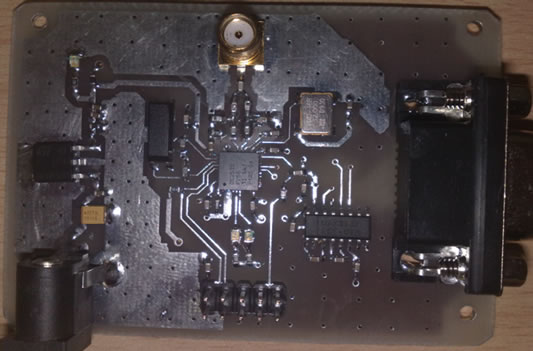
Figure 2. The hardware of the reader.
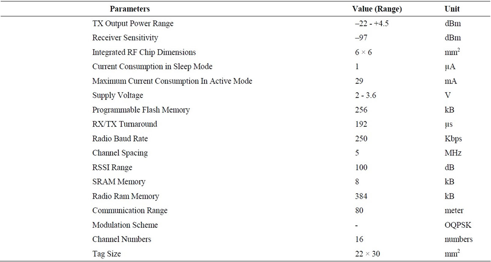
Table 1. Key parameters of the system [7].
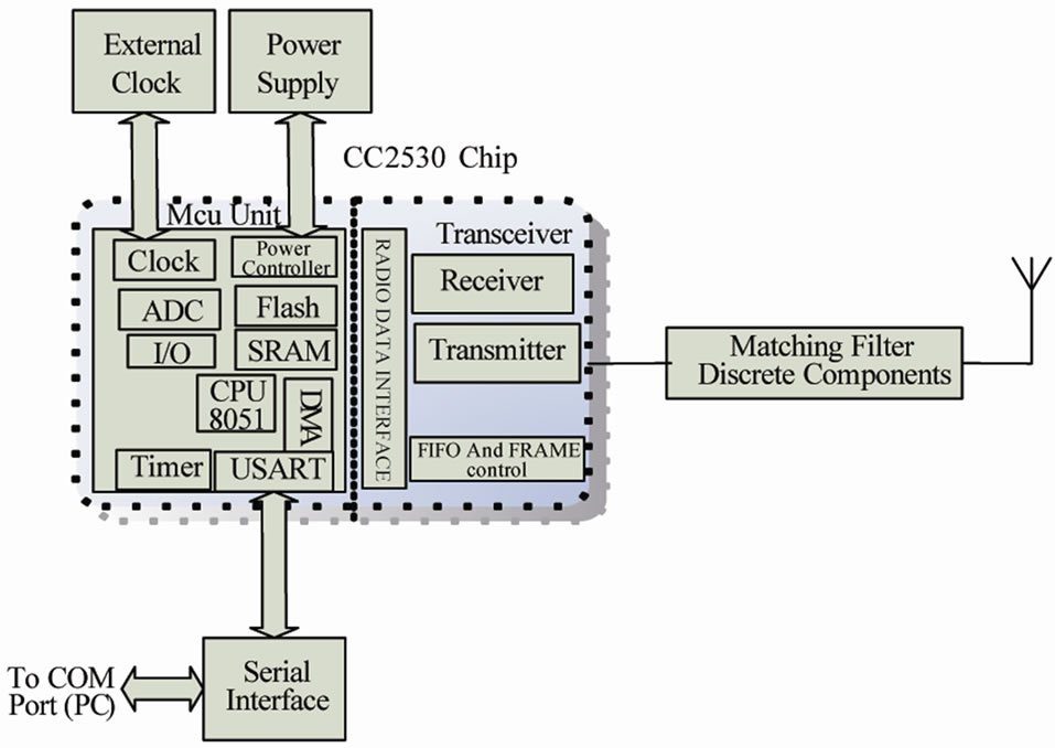
Figure 3. The block diagram of the reader hardware.
ware design is an aspect, and the software algorithm of Tags is also another key factor to decrease the power consumption. There are three kinds of states in this algorithm as follows: sleep condition, survey condition, and communication condition. The hardware of Tags is same with that shown in Figure 2, but it does not need any serial interface [2]. In general, in most of times, Tags are in the sleep condition. At this time all internal circuits of the Tag are inactive except the low-frequency clock. The Tag is woken up and interrupted by received data packets. Then Tag enters to the communication condition only when the received frames are from the Reader. After responding to the Reader command, Tag goes to the sleep mode. We compact the dimensions of Tags down to near 660 mm2. The block diagram of Tags is shown in Figure 4.
3. Software Development
3.1. Anti-Collision Protocol
Anti-collision protocol is critical in the performance of RFID systems. Without using an anti-collision protocol,
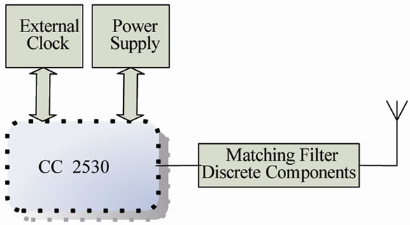
Figure 4. The block diagram of tags.
the responses from the Tags would collide together and thereby prolong the identification process. So, collision causes the bandwidth and energy wastage. There are four main types of anti-collision schemes: space division multiple access (SDMA), frequency division multiple access (FDMA), time division multiple access (TDMA), and code division multiple access (CDMA). TDMA protocols are the largest group of anti-collision algorithms. These algorithms could be classified as the Reader-driven or Tag-driven procedure. Our scheme is based on the ReaderTalk-First (RTF) protocol, in which Tags remain silent until commanded or searched by the Reader. Tag driven procedures are slower than RTF. In the Pure-ALOHA (PA) procedure, Tags respond to the Reader at random instants. So the possibility of the collision increases. In Slotted-ALOHA (SA) based RFID systems, Tags transmit their ID in synchronous time slots. Our approach is based on the SA protocol. By this method, the round time and probability of the collision decrease, greatly [3]. Here, Tags respond to the Reader commands only at certain moments. If a Tag is present in the duration of this slide, it will respond to the Reader and then go to the sleep mode at the end of this slide until the next cycle. In our algorithm, a command frame includes 20 bytes. So, at the data rate of 250 kbps, it takes 0.5 ms to be transmitted, completely. The slide duration in our protocol is about 5 ms. One Tag is active only for a short time in
each cycle. The timing of SA-TDMA anti-collision protocol is shown in Figure 5.
3.2. Software Algorithm
As shown in Figure 6, we have considered three basic commands for our software. In ID allocate command, we dedicate an ID to each Tag. We search the Tag ID by the polling command and clear the Tag ID by the clearing command. This algorithm is implemented at high-level software which provides a user-interface tool on a PC. The ID allocation is performed as follows. A unique address and ID is dedicated to each Tag. The Reader receives the ID and address from the PC serial interface and then sends them to a Tag. This Tag saves ID as an identification number in the permanent memory. After receiving ID from Reader, it sends an acknowledge message to the Reader. This message confirms the successful ID allocation of the Tag. Then we allocate the ID to another Tag. This process is repeated for all Tags by the user until every Tag will have a unique identification number.
The whole flowchart of the RFID Reader is shown in Figure 7. The Reader waits for the user commands from the serial port. In this situation, the RF transceiver of the Reader remains in the idle state. By reception of any command from PC, the Reader interprets the command and executes it. By using the ID-Allocation command, each Tag will have a unique identification number, and subsequently the user can search Tags by their unique IDs. When we want to remove an ID, we use the clearing Tag command. By performing this command, the given Tag loses its ID and it will no longer has passing permission.
All Tags have monotonous routine in the soft protocol. They should react to the user commands that come from the Reader. In fact, Tags should be synchronous with the
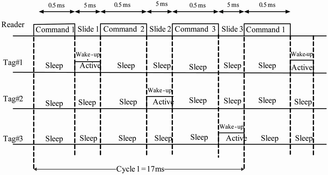
Figure 5. The timing of the anti-collision protocol.
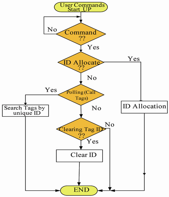
Figure 6. The flowchart of the user-interface software.
Reader. In practice, Tags are always located in inactive mode. In this mode, only internal low-power 32.768 kHz oscillator is active and all other components are dormant. In this mode, by using of the sleep timer, external events such as radio signals can be detected. Whenever SFD (Starting Frame Detector) from the received packet is detected, an interrupt will be occurred. We implement this interrupt source for synchronizing the Tags with the Reader and for reducing the power consumption in Tags. After SFD detection, Tags Wake up and go to the survey condition. Now, Tags receive whole of the frame. If the source address within the frame does not match with the Reader address, Tags do not pay attention to this frame any further and go to the sleep mode immediately. But when the source address is identical with the address of the Reader, Tags look for the type of the frame command within the frame. As shown in Figure 8, Tag goes to the communication condition for these three commands: ID allocation, polling, and clearing the Tag ID. When polling and clearing commands are coming from PC, at first, Tag checks the Destination address with the address of itself. Tag only acts when these two addresses are identical. After executing any of these commands, Tag goes to the sleep mode for other receptions. So, by this way, Tags always listen to the channel and after processing any event they go to the low power consumption mode, immediately.
3.3. Zig-Bee IEEE 802.15.4 Frame Format
IEEE 802.15.4 is an efficient standard for MAC protocol. There are 4 types of MAC frames in this standard. In our work, we use the data frame for communication between the Reader and Tags. In Figure 9, the schematics of MAC and physical layers of 802.15.4 are shown. SHR (Synchronization Header) is added at the first of any frame for synchronization between the Reader and Tag. The SHR consists of the 4-byte preamble sequence and 1-byte SFD. These two fields are set automatically by the hardware. In the PHR (Physical Header), the length of MPDU (MAC Protocol Data Unit) is written. The SHR and PHR are placed at the physical layer of 802.15.4 standard. The Radio has a FIFO memory with 128 bytes capacity. FCF (Frame Control Field), data sequence, address information, frame payload, and FCS (Frame Check Sequence) create the MAC layer. The Radio supports the automatic calculation of 2-byte FCS. By using of the source and destination addresses, each device will have a unique address, which helps us provide a precise timing in the polling process. Moreover, IEEE 802.15.4 is equipped with frame filtering and AUTOCRC protection. It rejects non-compliant frames, so decreases the packet error rate [7].
4. Experimental Results
In Figure 10, all the 16 channels are shown in the spectrum analyzer with a high precision. By using of a powerful RF transmitter, all out of band frequencies are filtered and the main frequency is amplified. The receiver sensitivity is a critical parameter for correct operation of RF transceivers. In CC2530, the receiver sensitivity is –97 dBm [7]. So, if the received signal strength (RSSI) becomes lower than this level, the receiver will not detect the signal properly. In Figure 11, the RSSI versus distance between the Reader and Tags is depicted in a practical test. For lower transmitter output power, the RSSI value is decreased. This reduction in RSSI is often more for long distances rather than short distances. As shown in Figure 11, the RSSI level is higher than the receiver sensitivity threshold for distances smaller than 80 meter. The PER (Packet Error Rate) is another significant parameter in RFIDs. It is expressed in the form of percentage. As shown in Figure 12, the PER is increased with increasing the distance, significantly. The experiments were performed for the two different TX output powers to ensure the proper operation of this system. As shown in Figure 13, round time for collecting 170 Tags data is near 1 second. In Table 2, important parameters of this system compared with similar works are shown.
5. Conclusion
In this work, a low-power high-range active RFID is implemented by using the chip CC2530. Without using any additional peripheral module, the identification process is
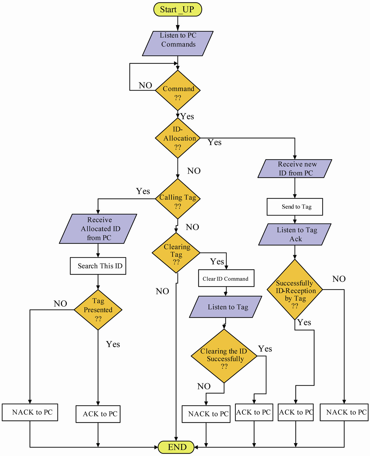
Figure 7. The reader flowchart.
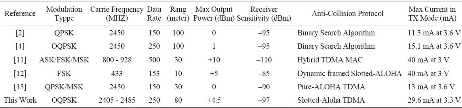
Table 2. System characteristics of similar RFIDs.
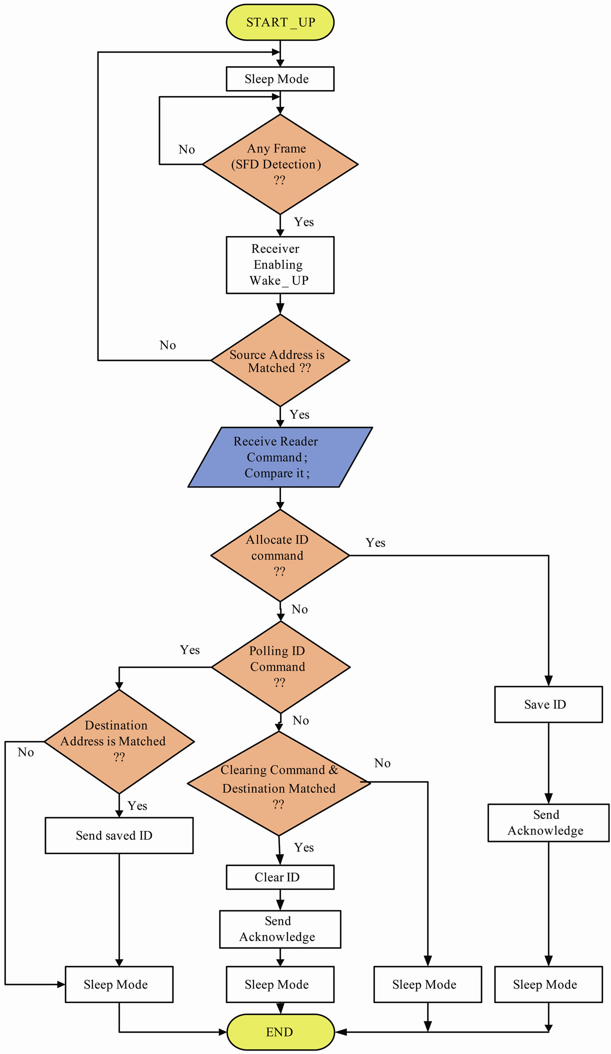
Figure 8. The flowchart of tags operation.
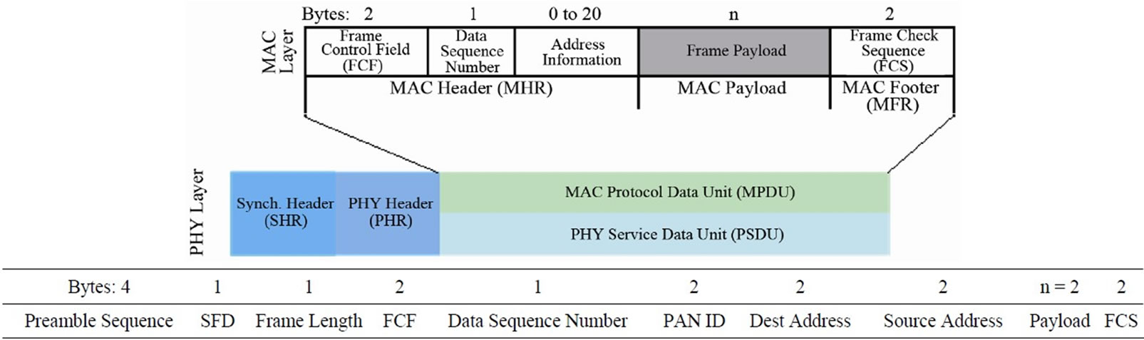
Figure 9. The physical and MAC layers of IEEE 802.15.4 standard frames [7].
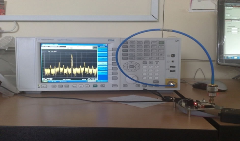
Figure 10. Frequency spectrum of the transmitting signal on spectrum analyzer.
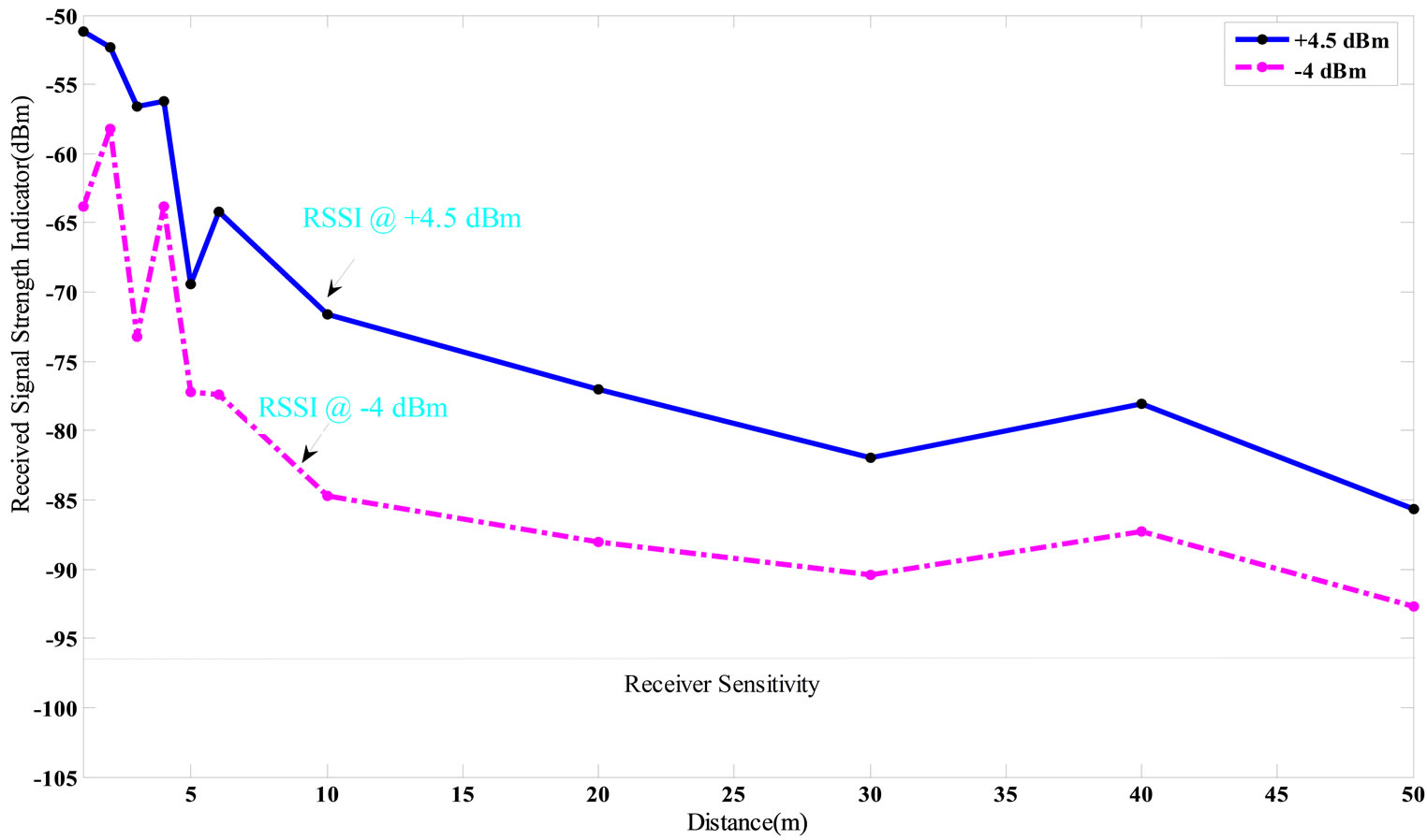
Figure 11. Received signal strength (RSSI) versus distance.
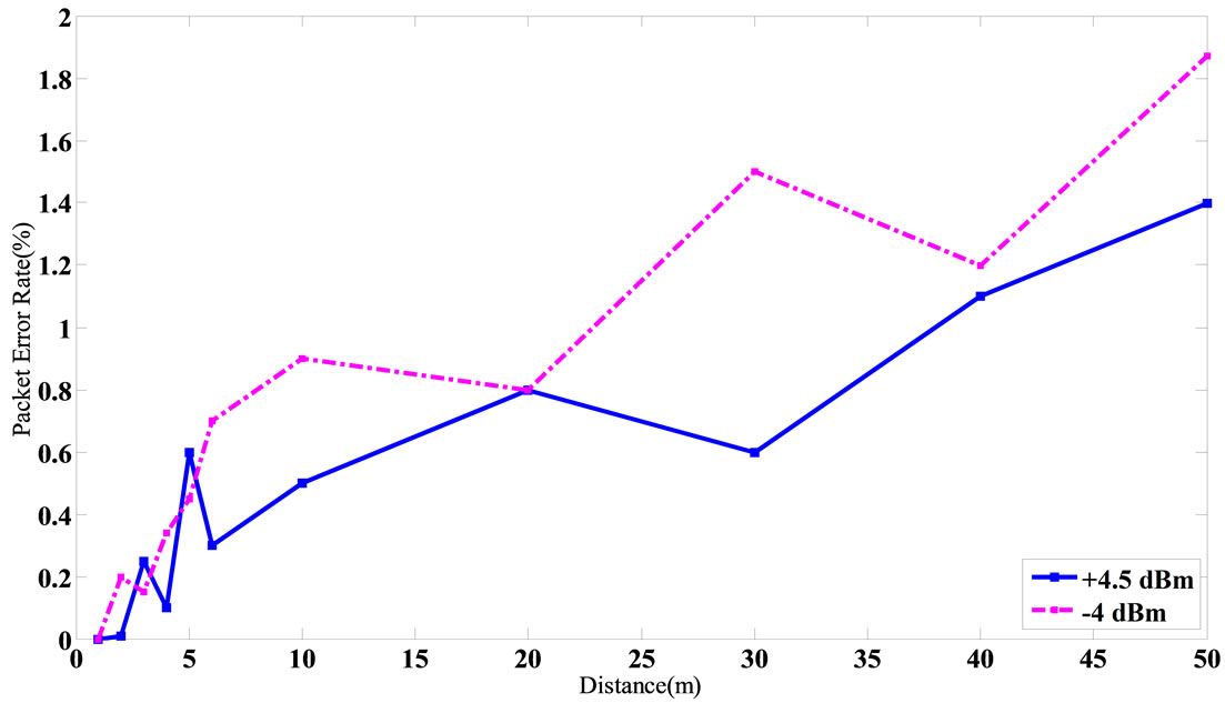
Figure 12. Packet error rate versus distance.
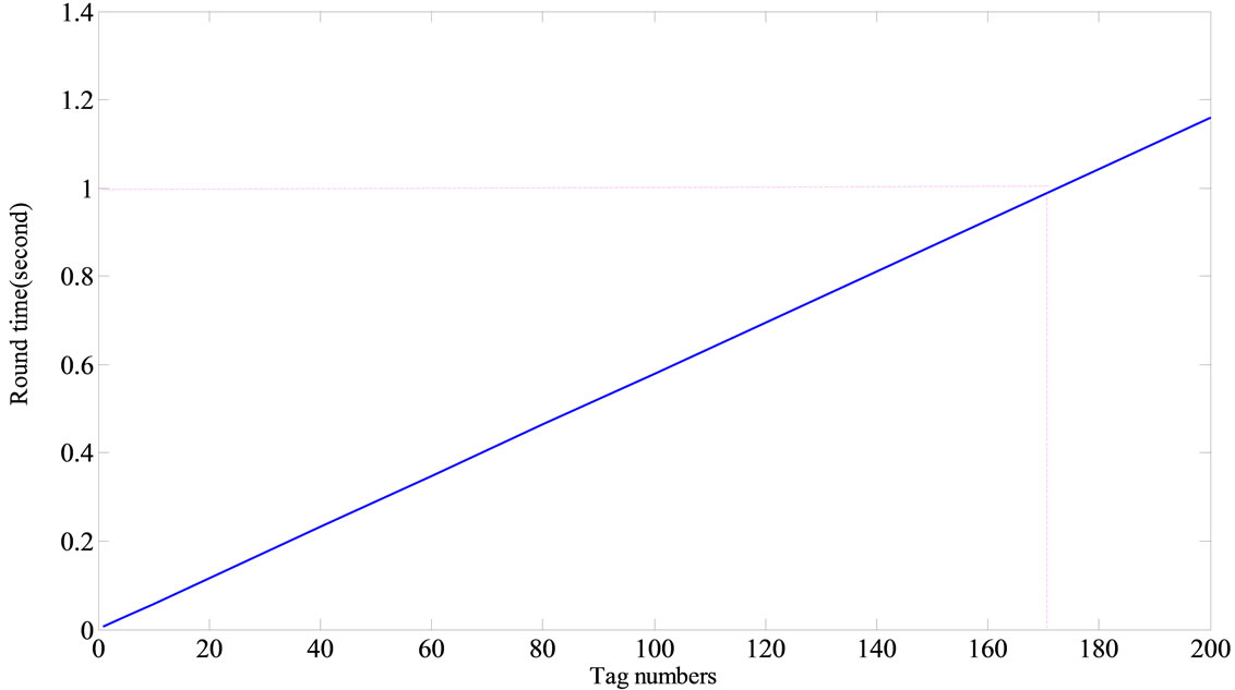
Figure 13. Round time versus tag numbers.
executed with high accuracy and minimum PER. By programming Tags in the sleep mode in most of times, a lot amount of power is restored. This system is tested and its operation is verified at outdoor environment until 80 meter distances, successfully. With a range extender device, such as CC2591, the communication range up to 300 m can be achieved. In our work, the collection time for 170 Tags is near 1 second. By using of a low-power multi-purpose Chip, small dimensions for Tags are achieved. In this architecture, compacting Tags down to near 660 mm2 is possible, which is required in many practical environments. This system will be used for vehicle transportation and especially container tracking at commercial ports.
REFERENCES
- Z. Min, L. Wenfeng, W. Zhongyun, L. Bin and R. Xia, “A RFID-Based Material Tracking Information System,” 2007 IEEE International Conference on Automation and Logistics, Jinan, 18-21 August 2007, pp. 2922-2926.
- Y. Sun, Y. Zhang and P. Peng, “Design and Realization of 2.45 GHz Active RFID System,” 2nd International Conference on Intelligent Computation Technology and Automation, Changsha, 11 October 2009, pp. 582-585. doi:10.1109/ICICTA.2009.147
- D. K. Klair, K.-W. Chin and R. Raad, “A Survey and Tutorial of RFID Anti-Collision Protocols,” Communications Surveys & Tutorials, Vol. 12, No. 3, 2010, pp. 400- 421. doi:10.1109/SURV.2010.031810.00037
- X. Huang, G. Zhang, Q. Sun and D. Qing, “Container Transportation System Using 2.45 GHz Active RFID Technology,” International Conference on Remote Sensing, Environment and Transportation Engineering, Nanjing, 24 June 2011, pp. 3030-3033. doi:10.1109/RSETE.2011.5964953
- W. J. Yoon, S. H. Chung, S. J. Lee and Y. S. Moon, “Design and Implementation of an Active RFID System for Fast Tag Collection,” 7th International Conference on Computer and Information Technology, Fukushima, 16 October 2007, pp. 961-966.
- H. Cho and Y. Baek, “Design and Implementation of an Active RFID System Platform,” International Symposium on Applications and the Internet Workshops, Busan, 23 January 2006, pp. 1-4.
- Texas Instruments, CC2530 User Guide and Datasheet, April 2009. http://www.ti.com
- Y. Hao and Z. Hong, “Development of a Low-Cost Active RFID Platform,” IEEE 2007 International Symposium on Microwave, Antenna, Propagation, and EMC Technologies for Wireless Communications, Hangzhou, 16 August 2007, pp. 152-155.
- Maxim, MAX3232 Datasheet, 2007. http://www.maxim.com
- X.-Z. Zheng, X.-H. Cao and W.-L. Zheng, “Design of Electronic Tag in Active RFID Systems,” Port Operation, Vol. 1, No. 2, 2008, pp. 850-853.
- Z. H. Xie and S. L. Lai, “Design and Implementation of an Active RFID MAC Protocol,” International Conference on Wireless Communications, Networking and Mobile Computing, Shanghai, 21 September 2007, pp. 2113-2116.
- H. Cho, H. Choi, W. Lee, Y. Jung and Y. Baek, “LITeTag: Design and Implementation of an RFID System for IT- Based Port Logistics,” Journal of Communications, Vol. 1, No. 4, 2006, pp. 48-57.
- U. Bilstrup and P.-A. Wiberg, “An Architecture Comparison between a Wireless Sensor Network and an Active RFID System,” 29th Annual IEEE International Conference on Local Computer Networks, Tampa, 16 November 2004, pp. 583-584. doi:10.1109/LCN.2004.17