International Journal of Geosciences
Vol.4 No.10A(2013), Article ID:41472,8 pages DOI:10.4236/ijg.2013.410A001
Influence of Stope Design on Stability of Hanging Wall Decline in Cibaliung Underground Gold Mine
1Department of Earth Resources Engineering, Faculty of Engineering, Kyushu University, Fukuoka, Japan
2Department of Geology Engineering, Mining Engineering Study Program, Hasanuddin University, Makassar, Indonesia
3Department of Mining Engineering, Faculty of Mining and Petroleum Engineering, Bandung, Indonesia
Email: purwanto11r@mine.kyushu-u.ac.jp
Copyright © 2013 Purwanto et al. This is an open access article distributed under the Creative Commons Attribution License, which permits unrestricted use, distribution, and reproduction in any medium, provided the original work is properly cited. In accordance of the Creative Commons Attribution License all Copyrights © 2013 are reserved for SCIRP and the owner of the intellectual property Purwanto et al. All Copyright © 2013 are guarded by law and by SCIRP as a guardian.
Received September 18, 2013; revised October 19, 2013; accepted November 17, 2013
Keywords: Stope; Hanging Wall; Decline; Cut and Fill; Cibaliung
ABSTRACT
Cibaliung Underground Gold Mine applies cut and fill mining method to optimize ore production and maintain underground stability. Existing 5 m × 5 m height and width of stope geometry has a potential new design to increase production of gold due to variety of thick ore, however serious shotcrete failures often occur in hanging wall decline. This paper aims to find out the relationship between stope design and stability of hanging wall decline. The analysis conducted in this study is based on underground characteristics and geological condition of Cibaliung area. The impact of stope design on decline stability was analyzed by using numerical methods. The impact factors such as different rock mass, size of stope, and distance between stope and hanging wall decline were used in the analysis of underground stability especially stability on hanging wall decline.
1. Introduction
Cut and fill mining is a selective open stope mining method and is applied for steeply dipping high grade deposit in weak host rock. This method has several advantages including suitable to follow irregular orebodies and easier to control the stability, especially in weak rock mass. Meanwhile, this method has several disadvantages; one of the disadvantage is low on cycle time production.
Cut and fill method recently has been widely used for underground mining in the world. Several gold mining in Indonesia applied this method including Nusa Halmahera Mineral (NHM), Aneka Tambang (Antam) Pongkor, and Cibaliung underground gold mine. Cibaliung underground gold mine located in Banten province is one of the gold mines in western part of Java Island in Indonesia. Map of study area is provided in Figure 1. This mine is operated under Cibaliung Sumberdaya Company (CSD). The resources of gold deposit are estimated amount 1.5 million of ore with grade 9.8 ppm.
In order to develop stope excavation, it is essential to understand the stability of multiple excavations. The development of stope excavation also should consider the influence of adjacent opening excavation and influence stope geometry to decline stability because shotcrete failure has often occurred in hanging wall decline.
To support these studies, some parameters are required. The intact properties of rock, rock mass condition, and in situ stress are naturally geological parameters to analyze underground design and stability.
Excavation geometry, distance and position between openings, and support design are the responsibilities of engineer judgments based on their experience and analysis. Stope design has an impact on stope stability [1,2]. Although there have been many research works that focused on the interaction between underground openings [3-5], very few researches and publications are found for the influence of stope design on decline stability.
The Mathews method [6] was introduced in 1980 to predict open stope stability. This method is based on a stability graph; that is related to Mathews stability number (N) and the hydraulic radius (HR) of stope geometry. Mathews stability number (N) is influenced by rock mass and three other parameters including rock stress factor,
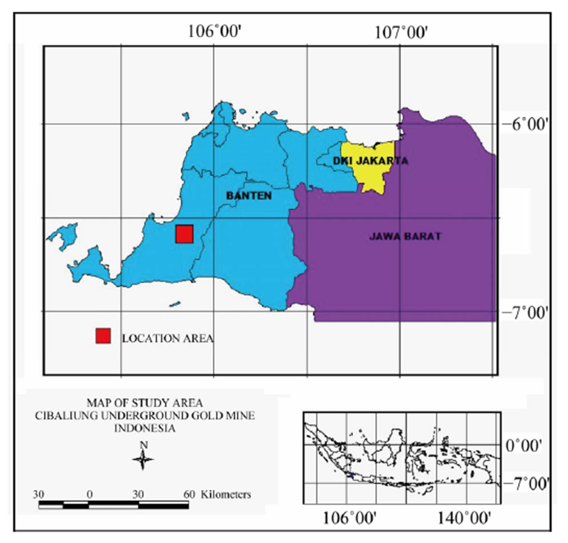
Figure 1. Location of Cibaliung underground gold mine (source: CSD).
joint orientation and design surface orientation, and size of an excavation surface (HR). However, this method is applied only for analysis of single stope stability. To consider the stability of multiple excavation, this paper highlighted results on simulation study of stope excavation influence on underground stability in cut and fill mine method.
Laboratory tests and field investigations are needed for a proper investigation of the properties of intact rock and rock mass. In this study, the properties of intact rock tests consist of UCS test, Triaxial test, and Brazilian test. This study combined field investigation and analysis of secondary data from underground company to classify rock mass.
2. Geological Condition of Study Area
The host rock of Cibaliung deposit is andesite rock type that consists of andesite, andesite breccia, polymictic, and monomictic breccia. Those host rocks are altered by chlorite-adularia and smectite-illite. The type of ore is a vein with low sulphidation epithermal deposit dominated by quartz vein. This vein follows the Cibaliung fault within NNW-striking/ENE-dipping, with two shoot target Cikoneng and Cibitung ore shoot. The Cikoneng ore geometry is 250 m length, 2 - 10 m width and 200 m depth, whereas Cibitung shoot geometry is 150 m length, 1 - 15 m width and 300 m depth with dip of ore is 80˚. The geology of Cibaliung can be seen in Figure 2.
The mine has been developed up to 100 meter depth. Overhand cut and fill method is applied in this mine. Two decline main ways are developed to support the production of mine. Those positions are in hanging wall
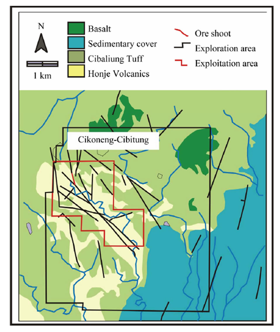
Figure 2. Regional geology of Cibaliung (source: CSD).
and foot wall. They are connected by cross cut to the ore stope. The decline of hanging wall consists of smectiteillite andesite breccia, while the foot wall consists of chlorite-adularia andesite breccia. The orebody consists of quartzite with some clay alteration.
3. Numerical Model
This research utilized Phase2®, a finite element method (FEM) software. Phase2® software is a two dimensional elasto-plastic finite element program to solve a wide range of mining engineering problems and to predict induced stress and displacements around underground openings or surface excavations. The program is convenient for analyses because of its easy for creating models, automatic mesh generation and many information results including displacement, stress, strength factor, and yield zone.
The basic model used in the analysis is shown in Figure 3. This model represents the typical geometry and geological conditions of cut-and-fill mine method especially in Cibaliung underground gold mine. Three underground excavations are designed including footwall decline, hanging wall decline, and stope excavation. The declines geometry both on foot wall and hanging wall are 4.2 m width and 4.8 m height. Meanwhile, standard stope geometry is 5 m width and 5 m height. The distance between stope to footwall decline (d1) set fixed as 20 m. The distance between stope to hanging wall decline (d2)
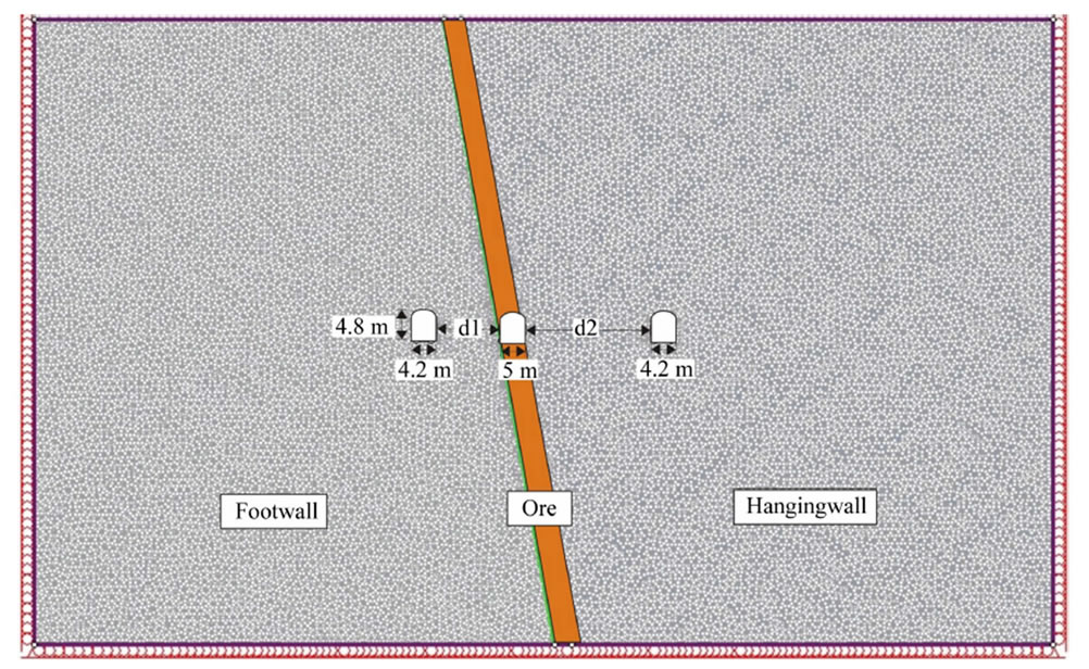
Figure 3. Initial condition for distance influence modeling.
was simulated. Three rock types are consisted in the location include breccia andesite with chlorite altered at footwall, breccia andesite with smectite altered at hanging wall, and quartzite as the ore body. The boundary conditions were set as follows: the sides of the model were restrained perpendicular to each side, whereas the bottom of the model was restricted in the vertical direction, and the top surface was free.
Dip of ore body is 80˚ and the thickness are varies between 5 m to 15 m. This is a reason to analyze the stope geometry impact on hanging wall decline failure.
Uniaxial compressive strength, triaxial compressive strength, Brazilian and density tests were conducted in accordance with the ISRM standard as parameters on numerical analysis. Based on the laboratory tests, some parameters are obtained including compressive strength (σc), young modulus (E), poisson’s ratio (n), cohesion (C), internal friction angle (ϕ), tension stress (σt) and rock density (ρ). The results of rock properties tests are summarized in Table 1. The values of minimum and maximum UCS varies, with the lower mean of compressive strength is in hanging wall rock. Hoek and Brown criterion was chosen due to the condition of field study consists of variations of rock masses. Table 2 shows the rock properties based on Geological Strength Index (GSI) system.
4. Result and Discussion
The analysis results include influence of rock mass, influence of distance between stope and hanging wall decline, and influence of stope size to decline stability will be explained following.
4.1. Influence of Rock Mass on Decline Stability
Two types of rock mass were analyzed in this study, poor rock mass (GSI 33) and good rock mass (GSI 53). Figure 4 shows the same size of geometry and distance between stope and hanging wall decline. It clearly indicates that rock mass gives high influence on decline stability. The yield zone occurs when the distance is 10 m for both of rock mass and overlap for both excavation in stope and hanging wall decline.
Figure 4 shows the percentage of yield element. The red color is 100% yield zone which means failure area. The yield element area on GSI 33 (Figure 4(a)) is wider than GSI 53 (Figure 4(b)). These results explain that poor rock mass has more failure potential than good rock. In addition, when the distance between stope and hanging wall decline increases, the yield zone decreases. The stability on the hanging wall decline occurs when the distance is more than 30 m for rock mass GSI 33. Otherwise, for good rock mass GSI 53, the stability has occurred when the distance is 20 m. According to the above analysis, the rock mass has influences on underground stability. For the poor rock mass, underground condition was weak and need more consideration for supporting planning.
4.2. Influence of Distance between Stope and Hanging Wall Decline on Decline Stability
Many researchers considered the influence of adjacent opening on mine and tunnel stabilities [7,8]. To increase the productivity, closely distance between decline and production area is important, however the stability should
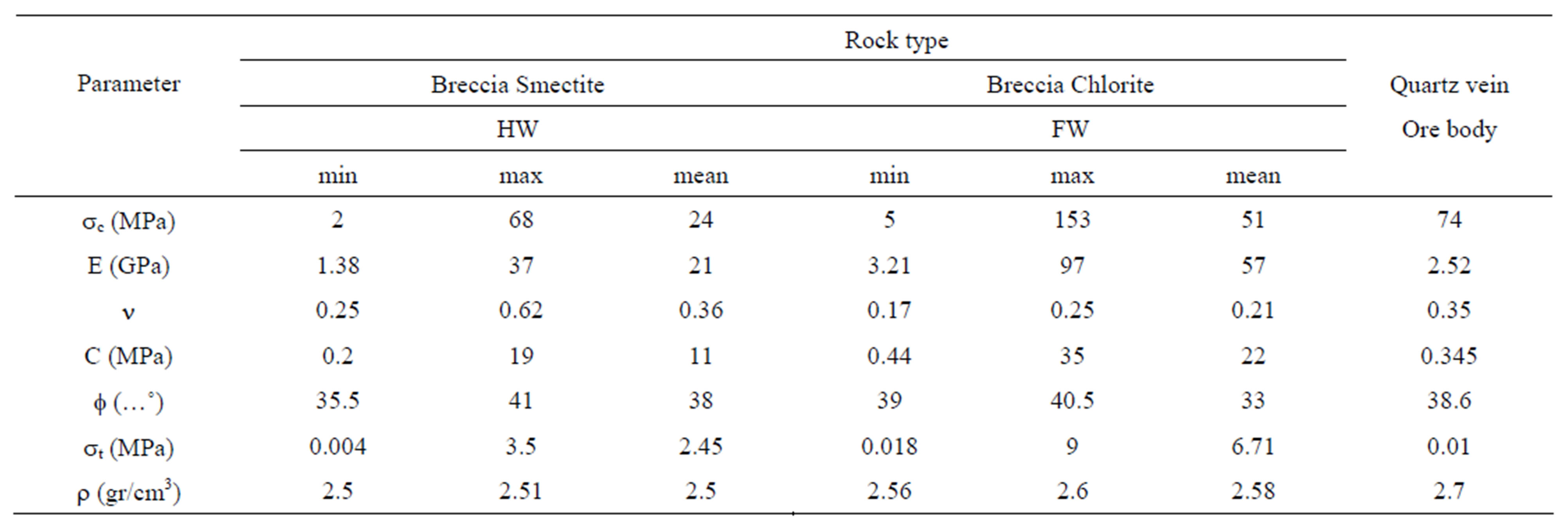
Table 1. Rock properties of Cibaliung underground gold mine.
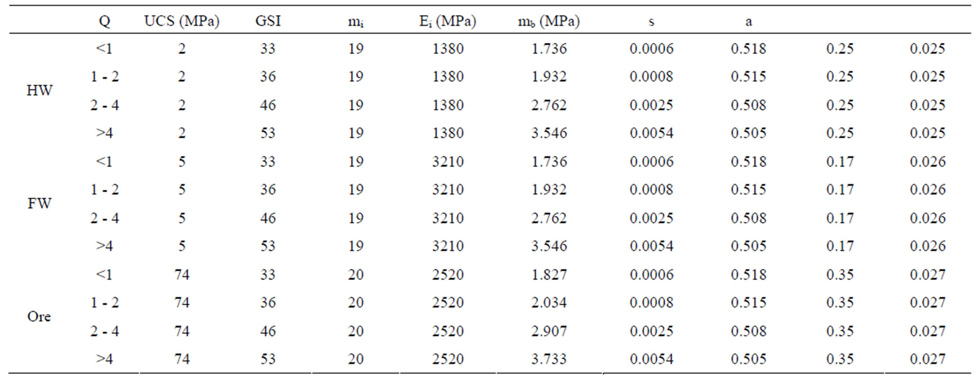
Table 2. Mechanical properties of rocks used in the analysis (GSI system).
be prioritized. In this study, the distances between stope and hanging wall decline were simulated as 10 m, 15 m, 20 m and 40 m. The geometry of stope was designed fix on 5 m width and 5 m height, and thickness of the ore is 5 m.
The model result (Figure 5) shows a correlation between displacement and distance on the decline excavation. When the distance is 10 m, displacement was 54.87 mm on the left side of hanging wall decline. The displacement decreases when the distance increases to 42.5 mm, 37.85 mm and 37.1 mm for distance 15 m, 20 m and 40 m, respectively. The displacement decreases significantly about 22.5% from distance 10 m to distance 15 m and tend to flat when the distance more than 20 m. Based on the change of displacement, it was found the effect of distance between stope and decline on hanging wall decline stability.
In addition, this effect also occurs in stope excavation. The displacement is biggest when the distance is 10 m and decreases with the increases of distance. Based on Figure 5, the comparison between left side and right side also was analyzed. The displacement on left side is higher than the displacement on right side. This condition is impacted by the existing of stope excavation where the position is on the left of hanging wall decline.
There is a concept for two or more excavations in close proximity. This concept explained that if none of the zone of influence overlaps each other, the interaction between the excavations is negligible [8]. Based on Figure 6, it is clearly seen that the overlapping and distribution of failure zones around underground openings is strongly depends on the distance of adjacent excavations. When the distance of stope and hanging wall decline is 10 m, the yield zone on the hanging wall decline and stope are clearly overlapping (Figure 6(a)). This condition indicated that the instability occurred in underground. However, for stope size 5 m × 5 m, the stability of hanging wall decline and stope occurred when the distance was 20 m.
Induced stress for mining stability analysis is important, though Figure 7" target="_self"> Figure 7 shows that the induced stress change due to different distance of excavations. The in-
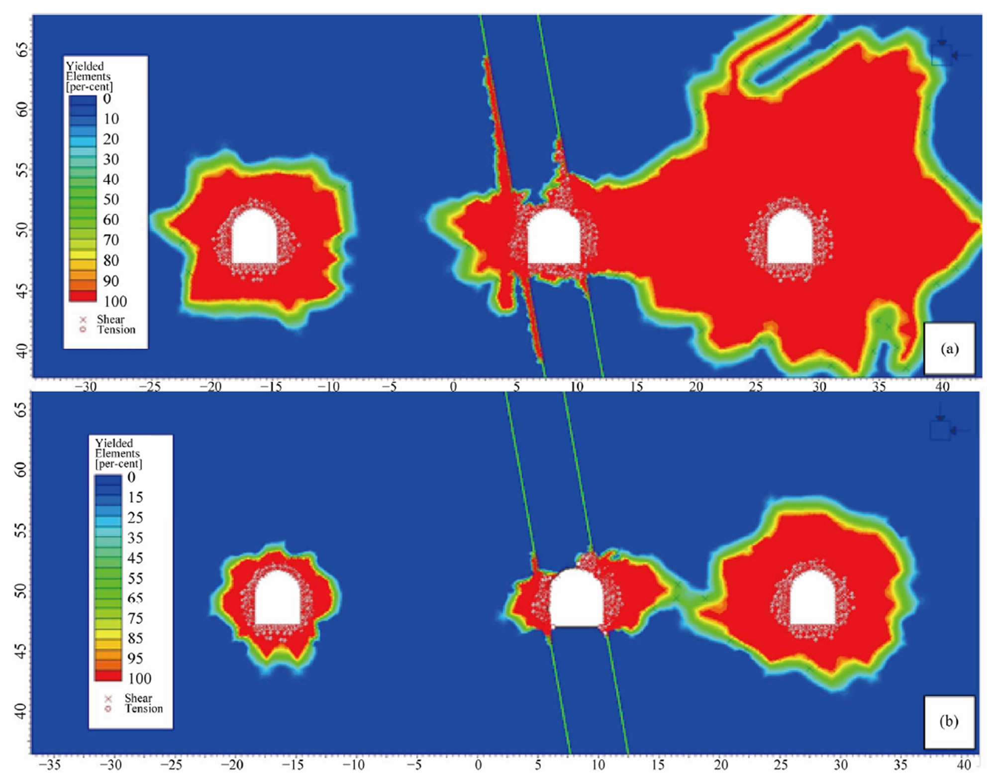
Figure 4. Influence of rock mass condition on hanging wall decline.
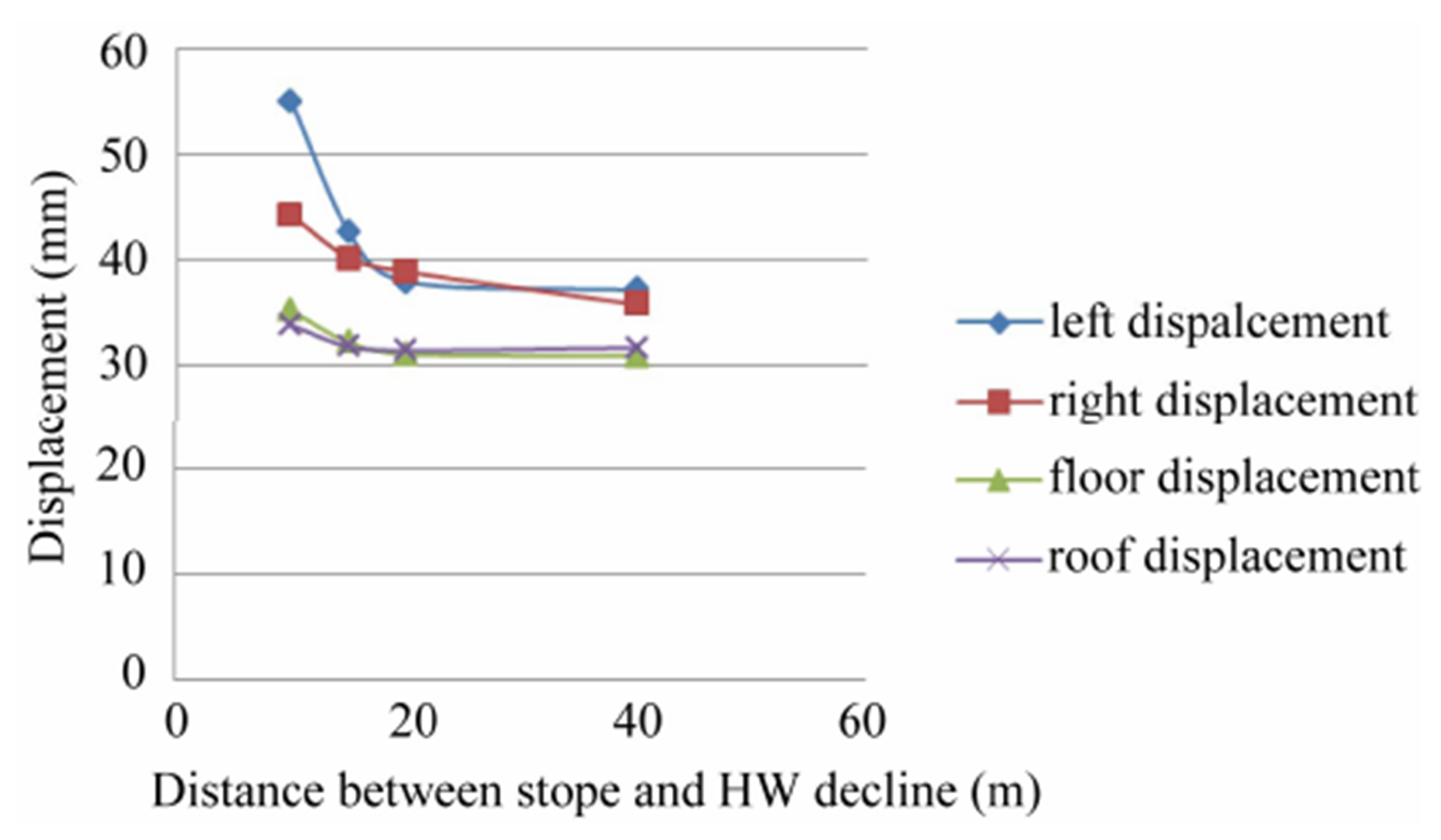
Figure 5. Influence of distance between stope and hanging wall decline on displacement.
duced stress referred in this study is the maximum induced stress (σ1). When the distance is 10 m, induced stress is lower than the others, but displacement overlapping was occurred. This condition has a high risk for failure correlated with Figure 6(a). When the distance is 15 m, the induced stress increases and become the highest stress compare to the others. This condition also has a high risk for failure surrounding the hanging wall decline. Maximum induced stress decreases when the distances are 20 m and 40 m, and the peak of stress to be double. Correlated to this condition, Figure 6(b) shows hanging wall decline was stable due to the yield zone did not overlap.
4.3. Influence of Stope Size on Decline Stability in Multiple Excavations
Eight difference stope sizes were simulated in this study to understand the influence of stope size. The shapes of stope excavation were made rectangular and cube to simplify. The distances between stope were 40 m for hanging wall decline and 20 m for foot wall decline. Various models of stope size were shown on Figure 8" target="_self"> Figure 8. In addition, Hydraulic Radius (HR) was used to express the stope size. HR is the area of the stope wall which divided by the perimeter.
Figure 9 shows the influence of different stope size. The influence of stope size to hanging wall decline was
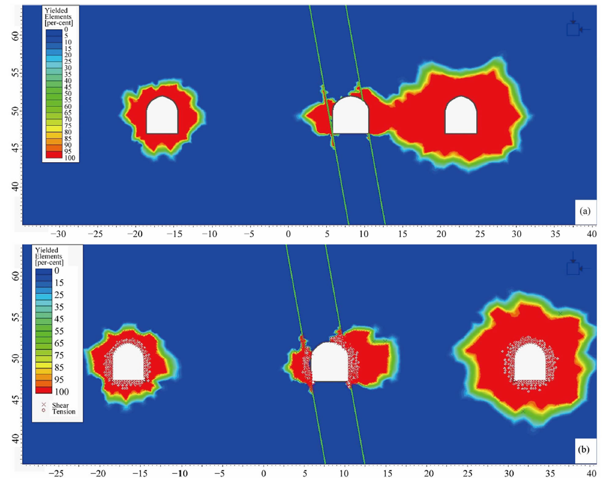
Figure 6. Influence of distance between stope and hanging wall decline on yield zone. (a) distance 10 m; (b) distance 20 m.
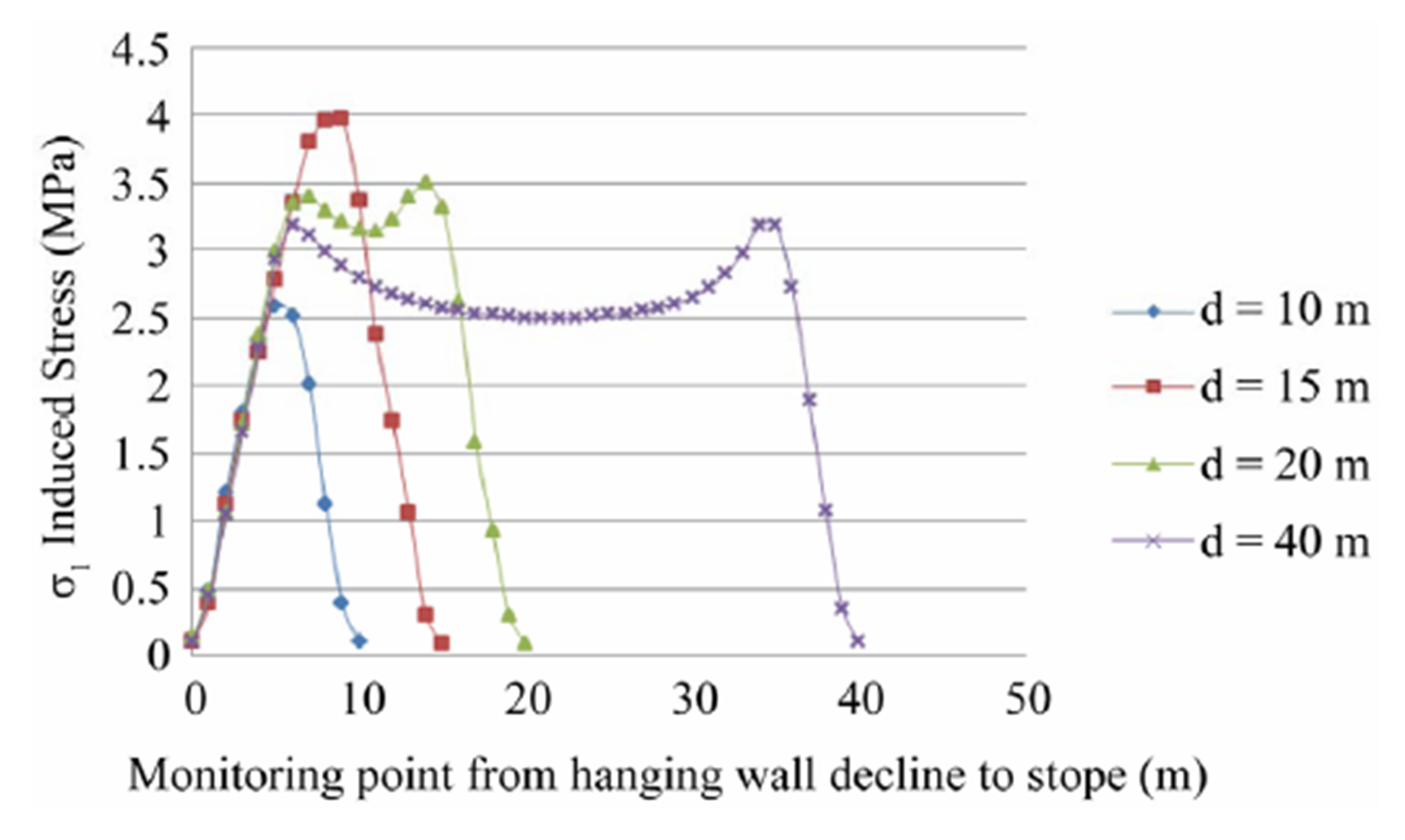
Figure 7. Influence of distance between stope and hanging wall decline on induced stress.
shown on the displacement by numerical modeling. The impact of stope size gave a trend of displacement to rise as the HR increase. For the 5 m stope height, maximum displacement was 51.6 mm and for the 10 m stope height the maximum displacement was 70.5 mm when the width was 20 m.
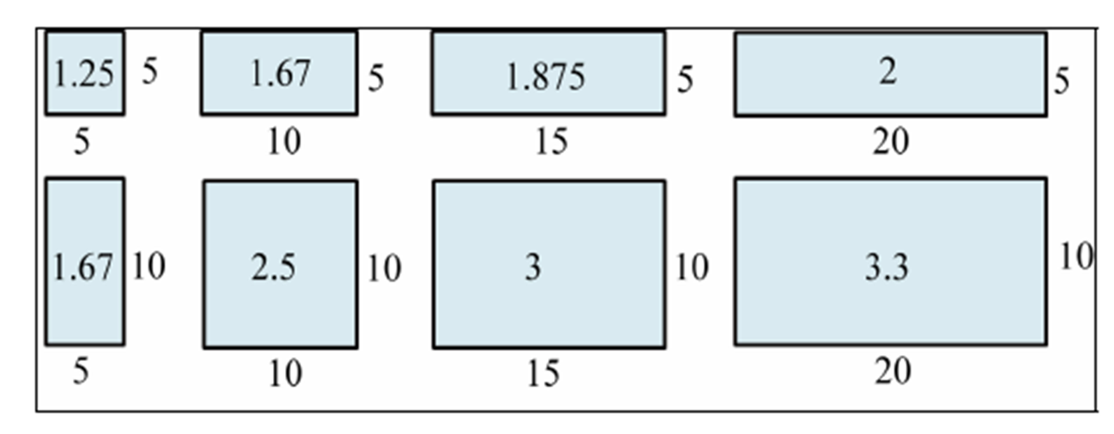
Figure 8. Stope size height and width in metres. Number inside is hydraulic radius.
The influence of stope size also can be seen in overlapping of yield element (Figure 10). For stope size 5 m × 10 m, the overlapping of yield element was not occurred (Figure 10(a)). The failure potential will occur when the stope width increased as 15 m (Figure 10(b)). Based on the yield element, failure occurred between stope and foot wall and has a risk to collapse. Similar condition occurs when the stope size is 10 m × 10 m. The overlapping occurs between stope and foot wall decline, not on the hanging wall decline.
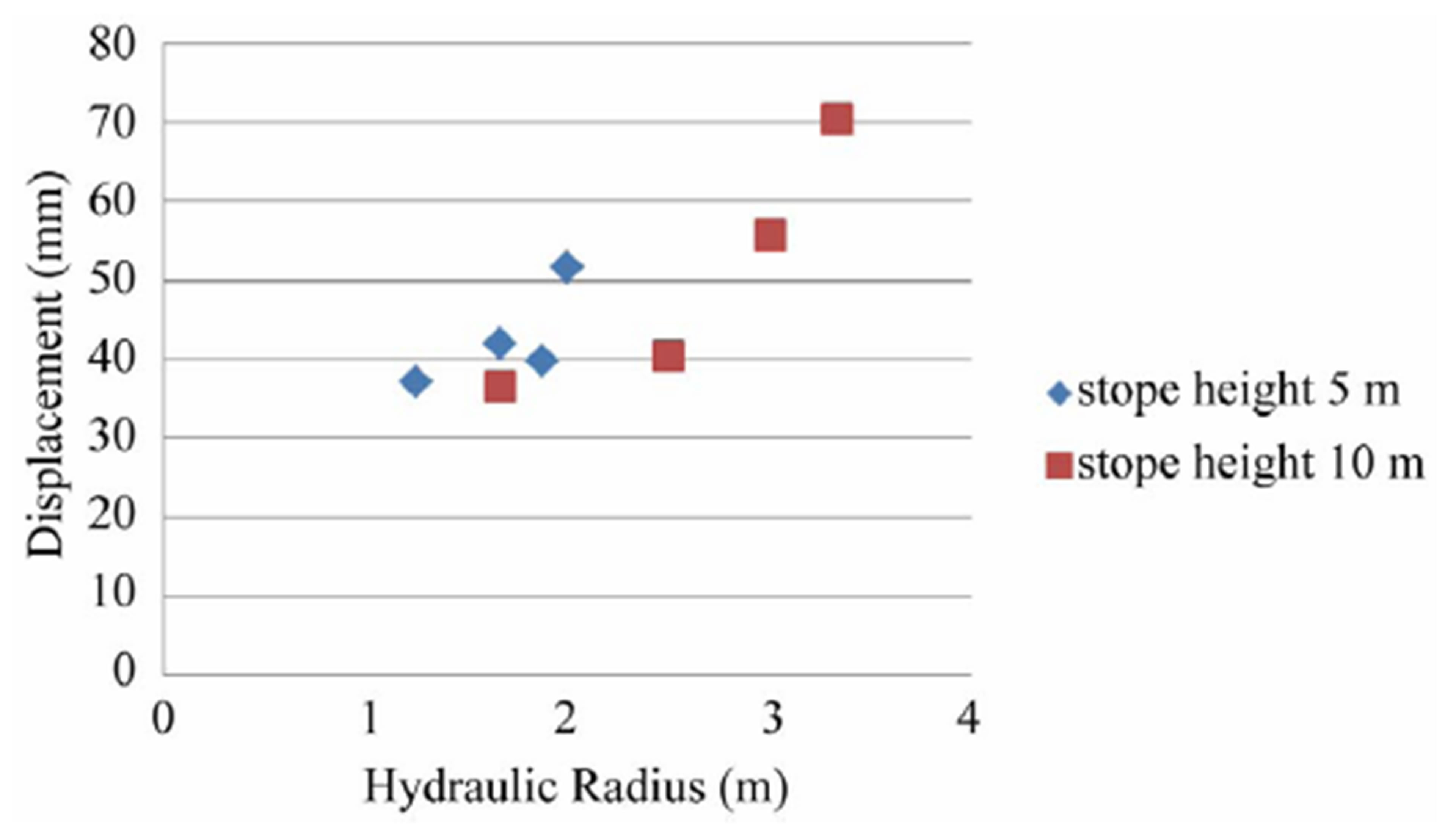
Figure 9. Influence of stope size on hanging wall decline displacement.
The Influence of stope size to hanging wall decline on induced stress can be seen in Figure 11 and Figure 12. Induced stress around the area between decline and stope tend to increase with the increase of stope size. There are two peaks of induced stress. It could be the effect of multiple excavations and elastic-plastic zone surrounding the excavations. Correlated with the displacement and yield zone, although the induced stress increase, the decline predicted stable for stope size 5 m height × 10 m width. For stope height 10 m, the results are relatively similar with stope height 5 m. The induced stress around the area between decline and stope tend to increase with the stope size.
5. Conclusions
In this study, the influence of the stope design on hanging wall decline stability was analyzed by numerical simulations. The impact factors such as different rock mass, different size of stope, different distance between stope and hanging wall decline were used as input parameters in the analysis.
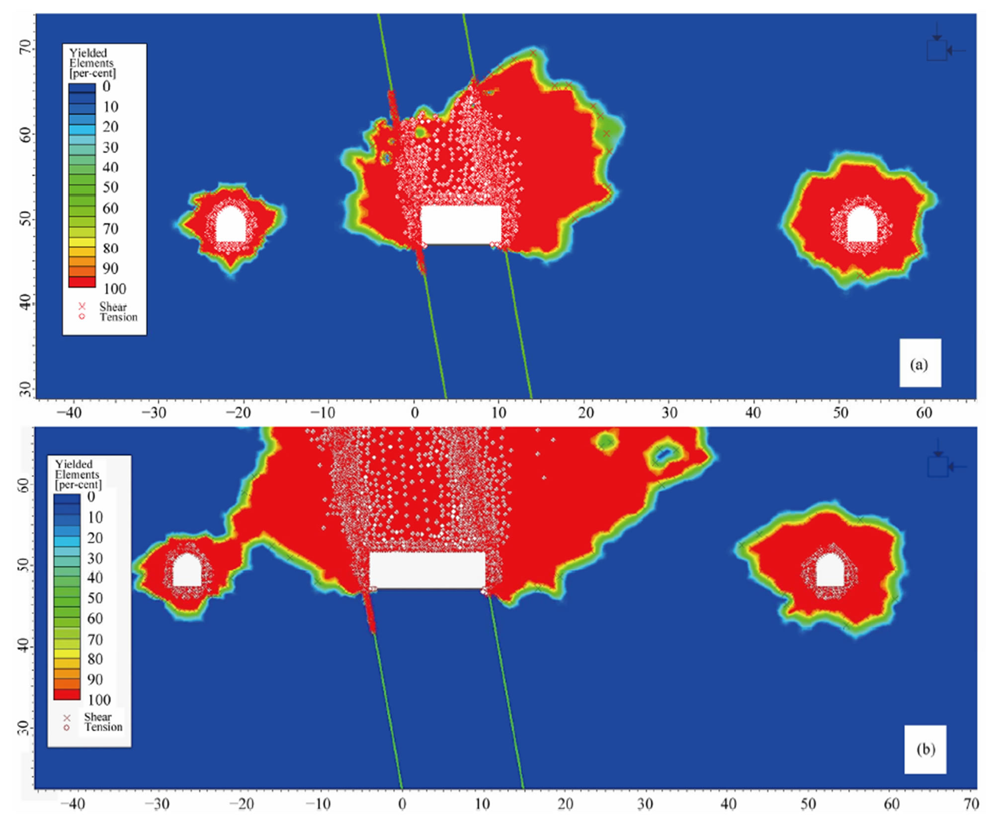
Figure 10. Influence of stope size on hanging wall decline yield zone. (a) Stope size 5 m × 10 m for height and width; (b) Stope size 5 m × 15 m for height and width.
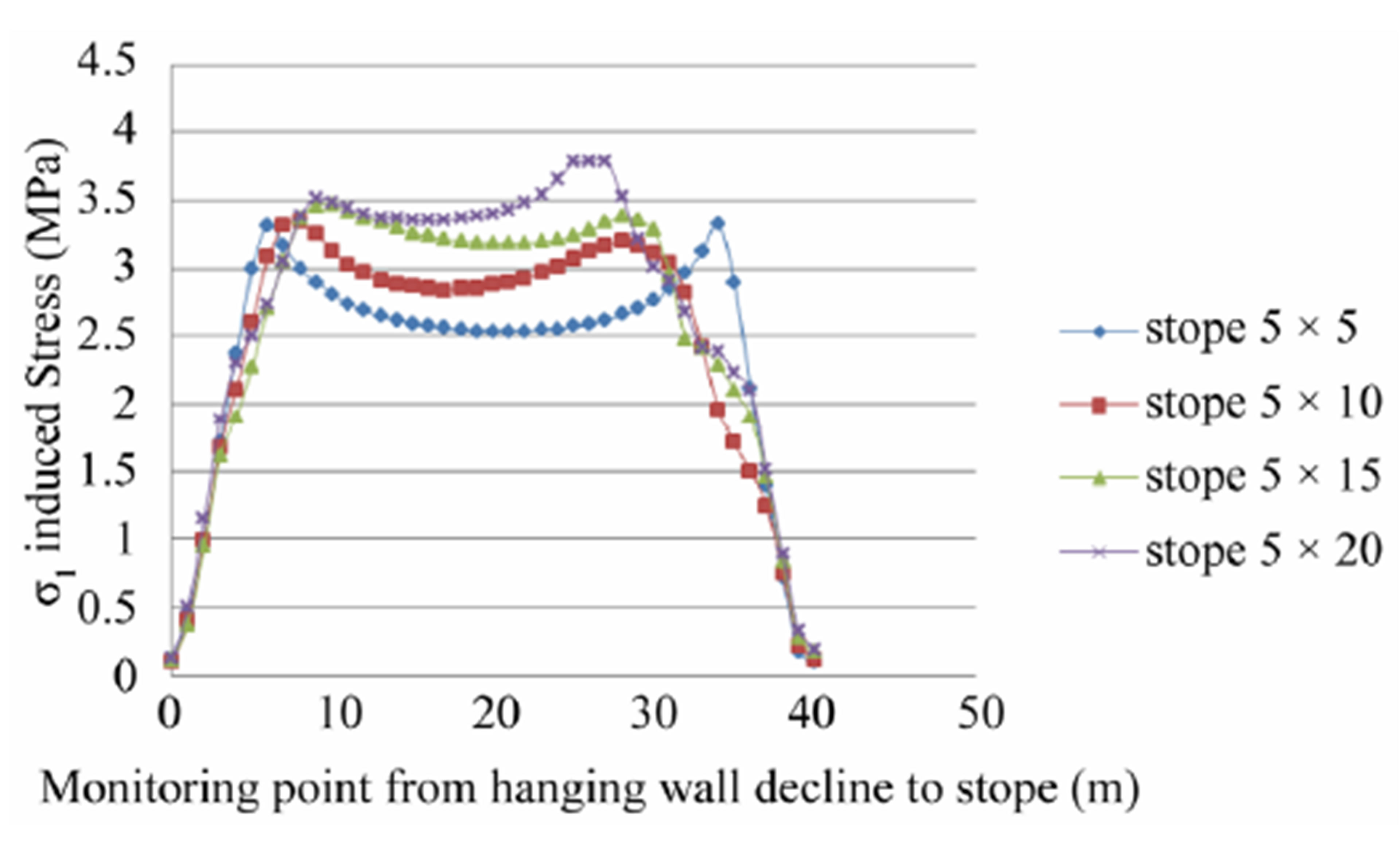
Figure 11. Influence of stope size on hanging wall decline induced stress (stope height 5 m).
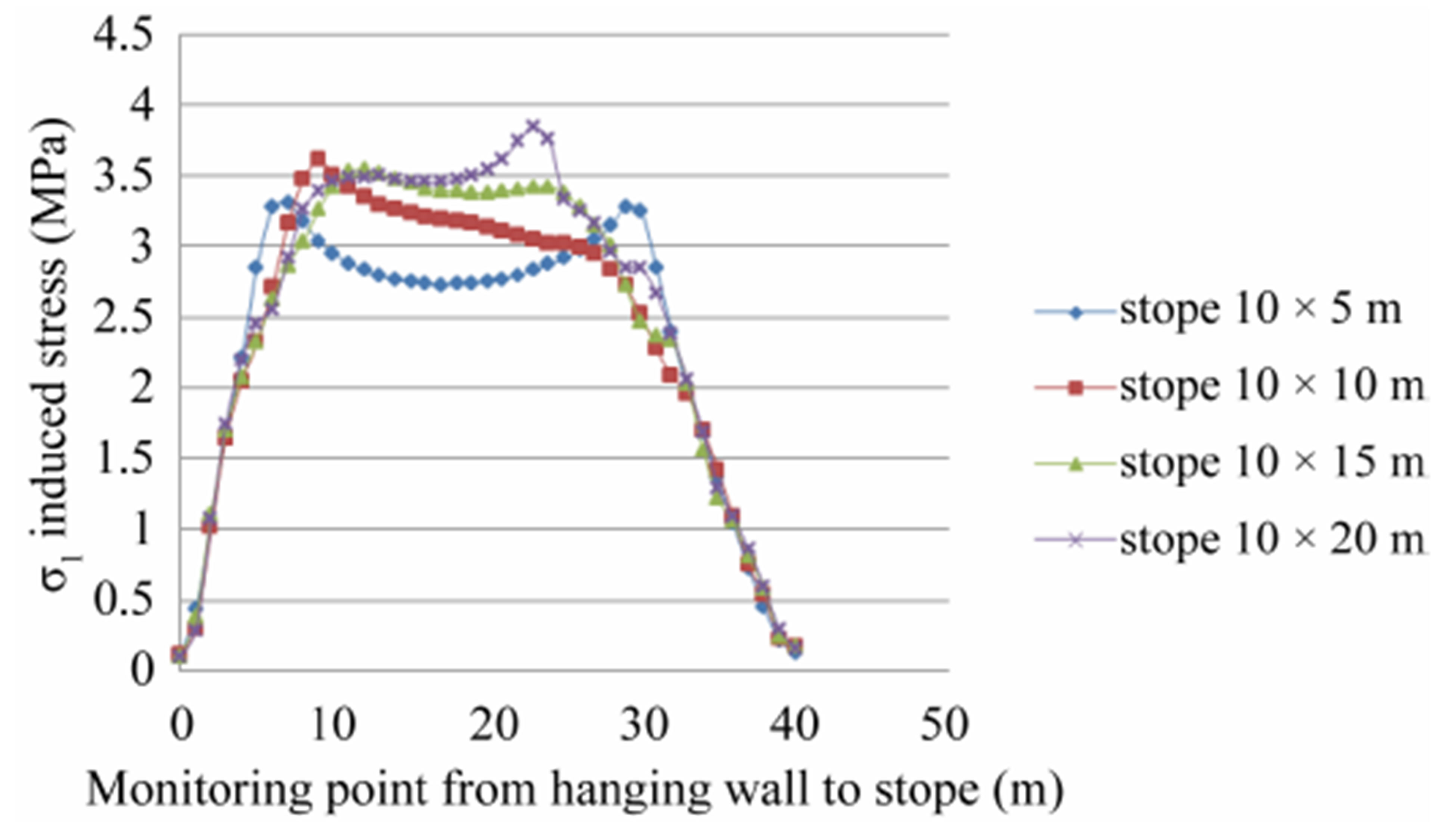
Figure 12. Influence of stope size on hanging wall decline induced stress (stope height 10 m).
From a series of numerical simulations, the impacts of different factors can be resumed as follows:
- Rock mass can lead to initiation of the stability of underground mine in the hanging wall decline. If the rock mass is weak, the instability risk is higher than the good rock mass.
- Deployment of yield zone of GSI 33 is wider than GSI 53 on the similar size of geometry. For the poor rock mass, failure predicted still occurs when the distance is 20 m. Otherwise, good rock mass has been stable for distance 20 m.
- The influence of distance between stope and hanging wall decline is clear based on the displacement on the hanging wall decline. The displacement decreases when the distances increase and the yield zone potential will occur when the distance between decline and stope is close.
- The influence of stope size on stability of hanging wall decline can be predicted by displacement and yield zone analysis. In general, the displacement tends to rise when the size of stope increases. When the stope size increase, the potential failure predicted firstly will occur on stope which needs to consider for stope design.
- The influence of distance on induced stress was not clear. The reason is that influence of stope design on induced stress also was affected by multiple excavations. However, when the stope size increases, the induced stress tends to increase in area around stope and decline.
Therefore, to increase the production, the stope design should be analyzed due to impact of stope excavation on hanging wall decline. It is especially interesting to research the induced stress in more detail to predict the failure potential and propose support design on decline of cut and fill mining.
6. Acknowledgements
The authors would like to acknowledge to PT. Cibaliung Sumberdaya management for the opportunity to conduct our research, and greatly appreciate Dr. Suseno Kramadibrata for continuous support for our research. First author acknowledge DIKTI—Indonesian Ministry of Education and Culture for granting PhD scholarship.
REFERENCES
- Y. Potvin, “Empirical Open Stope Design in Canada,” Doctoral Thesis, The University of British Columbia, Vancouver, 1988.
- C. Mawdesley, R. Trueman and W. J. Whiten, “Extending the Mathews Stability Graph for Open-Stope Design,” Mining Technology, Vol. 110, No. 1, 2001, pp. 27-39.
- G. Jamshid and E. R. Randall, “Interaction between Two Parallel Tunnels,” International Journal for Numerical and Analytical Methods in Geomechanics, Vol. 1, No. 1, 1977, pp. 75-103. http://dx.doi.org/10.1002/nag.1610010107
- J. Wang, D. Milne, L. Wegner and M. Reeves, “Numerical Evaluation of the Effects of Stress and Excavation Surface Geometry on the Zone of Relaxation around Open Stope Hanging Walls,” International Journal of Rock Mechanics & Mining Sciences, Vol. 44, No. 2, 2007, pp. 289-298. http://dx.doi.org/10.1016/j.ijrmms.2006.07.002
- H. Gercek, “Interaction between Parallel Underground Openings,” The 19th International Mining Congress and Fair of Turkey, IMCEV, 2005.
- Mathews, K. E. Hoek, D. C. Wyllie and S. B. V. Stewart, “Prediction Of Stable Excavation Spans for Mining at Depths below 1000 Metres in Hard Rock,” Report to Canada Centre for Mining and Energy Tehnology, 1980.
- Z. T. Bieniawski, “Rock Mechanics Design in Mining and Tunneling,” A.A. Balkema, Rotterdam, 1984.
- J. W. Bray, “Chapter 2: Some Applications of Elastic Theory. Analytical and Computational Methods in Engineering Rock Mechanics,” Allen & Unwin, London, 1987.