Journal of Flow Control, Measurement & Visualization
Vol.04 No.01(2016), Article ID:61826,12 pages
10.4236/jfcmv.2016.41001
Effect of Axial Clearance on the Flow Structure around a Rotating Disk Enclosed in a Cylindrical Casing
Takashi Watanabe1, Hiroyuki Furukawa2, Shohei Fujisawa1, Soma Endo1
1Graduate School of Information Science, Nagoya University, Nagoya, Japan
2Faculty of Science and Technology, Meijo University, Nagoya, Japan

Copyright © 2016 by authors and Scientific Research Publishing Inc.
This work is licensed under the Creative Commons Attribution International License (CC BY).


Received 10 June 2015; accepted 12 October 2015; published 10 December 2015

ABSTRACT
Numerical study is performed to investigate the swirling flow around a rotating disk in a cylindrical casing. The disk is supported by a thin driving shaft and it is settled at the center of the casing. The flow develops in the radial clearance between the disk tip and the side wall of the casing as well as in the axial clearance between the disk surfaces and the stationary circular end walls of the casing. Keeping the geometry of the casing and the size of the radial clearance constant, we compared the flows developing in the fields with small, medium and large axial clearances at the Reynolds number from 6000 to 30,000. When the rotation rate of the disk is small, steady Taylor vortices appear in the radial clearance. As the flow is accelerated, several tens of small vortices emerge around the disk tip. The axial position of these small vortices is near the end wall or the axial midplane of the casing. When the small vortices appear on one side of the end walls, the flow is not permanent but transitory, and a polygonal flow with larger several vortices appears. With further increase of the rotation rate, spiral structures emerge. The Reynolds number for the onset of the spiral structures is much smaller than that for the onset of the spiral rolls in rotor-stator disk flows with no radial clearance. The spiral structures in the present study are formed by the disturbances that are driven by a centrifugal instability in the radial clearance and they are penetrated radially inward along the circular end walls of the casing.
Keywords:
Rotating Disk, Cylindrical Casing, Bead-Like Flow, Polygonal Flow

1. Introduction
Flows around a rotating body and swirling flows around a stationary body give simple but important phenomena including Kármán flow, Bödewadt flow and Taylor vortex flow, and they have engaged historical interests in theoretical, experimental and numerical studies. The cylindrical rotor-stator cavity flow is the flow between a rotating disk and a stationary disk enclosed by an outer casing, and it presents one of the three-dimensional cross flow models [1] [2] . The rotation of the disk makes an Ekman layer on the rotating disk and a Bödewadt layer on the stationary disk. With an increase of the rotation rate of the disk, various flow patterns appear [3] , and the development of the flow has been investigated by experimental [4] and theoretical [5] approaches. In case of a narrow axial clearance [6] , the first instability of circular waves appears in the boundary layers on the rotating and the stationary disks, and the secondary instability of the spiral rolls emerges via Hopf bifurcation. Then, the solitary waves and the flows including turbulent spots appear. When the axial clearance is wide, the boundary layers are separated and the basic flow has a core region. In this flow, transitions appear through circular rolls, spiral rolls and wavy turbulence [7] - [9] . Two types of instabilities appear: type I instability based on the inflection of the velocity profile, which initializes spiral rolls at higher rotation rate, and type II instability concerned with the Coriolis force and viscous force, which promotes circular waves and spiral rolls at lower rotation rate [10] . When the axial clearance is very wide and it is comparable with the radii of the rotating and stationary disks, the axial flow becomes dominant and the vortex breakdown phenomena may emerge [11] .
Rotating flows can be found in fluid machinery and chemical reactors and they are examined to improve their performance [12] . When the flow around a rotating disk in a cylindrical casing represents a model of the flow in hard disk drives and stirrers, the radial clearance between the disk tip and the side wall of the casing is inevitable. Schouveiler et al. [13] implied that the radial clearance bores new spiral flows. Al-Shannag et al. [14] numerically examined the flow around corotating two disks connected by a central hub and showed the effect of the velocity fluctuation in the radial clearance on the interdisk flow. Hendriks [15] predicted a more realistic flow in a hard disk drive. He obtained Taylor vortices formed between the rotating disk and the side wall of the casing and found the jet-like radially outward flow on a rotating disk. Washizu et al. [16] examined the effect of a rib mounted on the sidewall of the casing and estimated the pressure fluctuation on the rotating disk. In these studies, while the characteristics of the unsteady flows were predicted, the effect of the rotation rate and the geometrical size of the disk were not clear. When the thickness of the rotating disk is comparable to the axial length between two circular end walls of the casing, the flow system in the radial clearance turns to Taylor-Couette system where the rotating disk corresponds to the inner cylinder. In Taylor-Couette system, the finiteness of the cylinder length breaks the idealization of axial periodicity of the dynamical structure in the flow [17] [18] . This means, even in the flow around a rotating disk, the end-wall effect on the onset and the development of Taylor vortices is one of the interesting topics of this flow. Watanabe and Furukawa [19] [20] numerically and experimentally investigated the flow around a rotating disk confined in a cylindrical casing. The disk driven by a thin shaft is settled at the center of the casing, and the flow field is symmetric with respect to the radial, azimuthal and axial directions. The radius of the disk is smaller than the inner radius of the casing. In the radial clearance between the disk tip and the side wall of the casing, the centrifugal instability causes flow disturbances and wavy flow appears. Several details about the effect of the radial clearance on the flow structure were numerically investigated by some of the authors [21] .
In this study, we estimate the effect of the axial clearance (aspect ratio) and the rotation rate. The sizes of the outer casing and the radius of the disk are fixed, and three disks with different thicknesses are introduced in order to adjust the aspect ratio. The flow fields with these disks show systematic development of flow structures, as well as structures special to each field.
2. Geometrical Model and Formulation
The schematic sketch of the flow field is shown in Figure 1 where the dimensionless sizes mentioned below are introduced. In the experiments we have assumed, the radius (Rd) and the thickness of the disk are 0.127 m and 0.03 m, respectively, and the inner radius and the height of the outer casing are 0.142 m and 0.04 m, respectively. The disk has a driving shaft of radius of 0.01 m at its center. The disk is placed at the center of the casing, and the axial clearance and the radial clearance are 0.005 m and 0.015 m, respectively. Two more disks with thicknesses of 0.032 m and 0.028 m are used. The angular velocity of the disk and the driving shaft is Ω. The reference velocity is the azimuthal velocity component at the tip of the rotating disk ΩRd and the reference length is the radius of the rotating disk Rd. All physical variables are made dimensionless by these reference values. The coordinate system is a cylindrical system (r, θ, z), and its origin O is at the center of the lower end wall disk of
 rc = 1.1181, rd = 1.0, rs = 0.0787, hc = 0.3150Disc 32: hd = 0.2520, hl = hu = 0.0315Disc 30: hd = 0.2362, hl = hu = 0.0394Disc 28: hd = 0.2205, hl = hu = 0.0472
Figure 1. Schematic sketch of the flow field and the coordinate system. The lengths are normalized by the disk radius of 0.127 m.
the casing. For the disks of thicknesses of 0.032 m, 0.030 m and 0.028 m, the aspect ratios Γ defined by the fraction of the dimensionless axial clearance hu (=hl) to the dimensionless disk radius rd are 0.0315, 0.0394 and 0.0472, respectively. Schouveiler et al. [3] have noted that these aspect ratios are intermediate and the basic flow between the rotating disk and the stationary disk is a mixed basic flow. The rotating hub (shaft) at the disk center increases the velocity fluctuations [22] , while the stationary hub decreases the fluctuation [23] . The effect of the central hub on the flow is estimated by the curvature parameter. In this paper, the curvature parameter defined by  is evaluated as 1.171. Poncet et al. [10] investigated the effect of the rotating hub on the flow. From their result, this value of the curvature parameter remains small enough and it does not have an influence on the critical Reynolds numbers for the onsets of circular waves and spiral rolls.
The discretization method is based on the finite difference method and the details of the numerical method can be found in our previous paper [19] . The Navier-Stokes equations and the equation of continuity are
 , (1)
, (1)
 (2)
(2)
where t is the time made dimensionless by 1/Ω, u is the velocity vector with its radial component u, azimuthal component v and axial component w, p is the pressure and Re is the Reynolds number defined by , where ν is the kinematic viscosity of the fluid. The staggered grid is adopted, and no singularity at the corners between moving and stationary boundaries appears.
The boundary conditions are given by the following equations:
On the inner stationary side of the casing
 (3)
(3)
 (4)
(4)
 (5)
(5)
On the rotating shaft and the rotating disk
 (6)
(6)
 (7)
(7)
 (8)
(8)
 (9)
(9)
 (10)
(10)
Initially, the flow is at rest and the disk is suddenly begins to rotate at a prescribed Reynolds number at t = 0.
The flow is observed in the axial section (i.e. (r, θ) plane), radial section (i.e. (θ, z) plane) and azimuthal section (i.e. (r, z) plane). The vortex structure of the flow is represented by the contour of the normalized helicity,
 (11)
(11)
where ω is the vorticity vector.
3. Flow Patterns
In this section, we mainly show the result of the flow at Γ = 0.0394.
3.1. Steady Vortex Flow in the Radial Clearance (Re = 6300)
When the Reynolds number is low, Taylor vortices appear in the radial clearance between the rotating disk tip and the side wall of the casing.
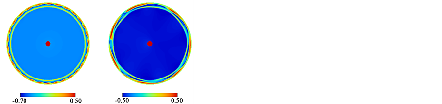
Figure 2 shows the contour of the helicity of the flow at Re = 6300. Figure 2(a) represents the flows at different times in the (r, θ) plane. The axial position z is 0.00984 and it is close to the lower stationary end wall of the casing. The central red circle denotes the driving shaft and the yellow region surrounding the shaft corresponds to the rotating disk. The disk is rotating in the counterclockwise direction. The flow at t = 60 is under development and its flow pattern is not axisymmetric. Figure 2(b) depicts the helicity in the (θ, z) plane. The azimuthal direction is horizontal. The radial position r is 1.10 and it is just inside of the side wall of the casing.
 t = 60 t = 300(a)
 t = 60
 t = 300
 −0.80 0.80(b)
 t = 60 t = 300(c)
Figure 2. Contour of the helicity at Γ = 0.0394 and Re = 6300. (a) Flow in the (r, θ) plane at z = 0.00984; (b) Flow in the (θ, z) plane at r = 1.10; (c) Flow in the (r, z) plane at θ = 0.0.
While the flow at t = 60 fluctuates in the azimuthal direction, the flow at t = 300 is well formed. Figure 2(c) shows the helicity in the (r, z) plane, where the radial clearance appears at the right side. In this figure, the warm color regions and the cold color regions represent the vortices rotating in the clockwise and counterclockwise directions, respectively.
After the sudden start of the disk rotation at t = 0, the flow at t = 60 is under development and the profile of the helicity exhibits its variation in the radial and azimuthal directions, and the flow pattern becomes axisymmetric by t = 300 (Figure 2(a)). This axisymmetric pattern was kept well beyond t = 400 and it was a final state. The azimuthal variation is also seen at t = 60 in Figure 2(b). At t = 300 in Figure 2(b), four straight bands (blue, red, blue and red from top to the bottom) appear, which correspond to four vortices formed in the radial clearance shown in Figure 2(c). In the rotor-stator flow system without the radial clearance, the Reynolds number for the onset of the flow instability is estimated 50,000 [3] and it is much higher than 6300 in Figure 2. This fact shows that the instability causing the vortex flow in the radial clearance is based on the different mechanism from that in the rotor-stator flow.
3.2. Transition from Bead-Like Flow to Polygonal Flow (Re = 7000)
When the Reynolds number is higher, a periodic pattern in the azimuthal direction appears in the fully developed flow. Figure 3 gives the flow at Re = 7000. Figure 3(a) shows the flow just below the rotating disk. At t = 70, small vortices (about thirty) periodically align in the azimuthal direction. In this paper, the flow with a series
 t = 70 t = 230(a)
 t = 70
 t = 230
 −0.80 0.80(b)
 t = 70, θ = 0.449 t = 230, θ = 0.823(c)
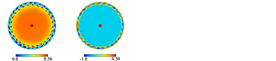
Figure 3. Contour of the helicity Hn at Γ = 0.0394 and Re = 7000. (a) Flow in the (r, θ) plane at z = 0.0374; (b) Flow in the (θ, z) plane at r = 1.09; (c) Flow in the (r, z) plane.
of these small vortices is named as a bead-like flow. The bead-like flow at this Reynolds number is not stable but it is transitory. The small vortices around the disk merge with each other at t = 120 to 200 and another stable state appears. The flow at t = 230 has polygonal (heptagon) flow around the disk tip.
The flow in the (θ, z) plane is shown in Figure 3(b). The vortex structure appears on one side of the end walls of the casing (in this case, the lower side of the casing), and the flow is not symmetric in the axial direction even though the geometrical configuration is symmetric. The spatial variation on one side of the end wall is also found in the (r, z) plane of the radial clearance in Figure 3(c). At t = 70, three main vortices emerge in the radial clearance. In addition to these three vortices, the lowest thin end vortex (the warmer color region at the corner between the side wall and the bottom end wall of the casing) appears, which is almost collapsed by the counterclockwise rotating vortex (the cold color region above the lowest end vortex). Along the boundary between these two vortices, where the bead-like pattern in Figure 3(a) appears, the flow is radially outward. The collapsing motion appears periodically in the azimuthal direction and it results in the formation of the bead-like flow. When the polygonal flow appears at t = 230, the amplitude of the deformation motion becomes large.
The counterclockwise rotating vortex causes radially outward flow near the bottom end wall. In Taylor- Couette system with finite cylinder length, the vortex with radially outward flow on the end wall is denoted as an anomalous vortex and the existence of the anomalous vortex explains one of the reasons why multiple flow modes appear [24] . In this study, the transition from the bead-like flow to the polygonal flow took place when the anomalous vortex emerged only on one side of the end walls of the casing. The polygonal flow with several vortices was also found in the flow between corotating disks with a central hub [25] [26] . These vortex flows have much larger flow structures than those found in the present study.
3.3. Steady Bead-Like Flow (Re = 8000)
Figure 4 shows the steady bead-like flow at Re = 8000, which does not transit to another flow pattern. This type of the steady bead-like flow has also been found experimentally [19] . In Figure 4(a), the axial positions z = 0.0374 and 0.278 are just below and just above the rotating disk, respectively. The bead-like flow with thirty
 z = 0.0374 z = 0.278(a)
 −0.30 0.30(b)
 (c)
(c)
Figure 4. Contour of the helicity Hn at Γ = 0.0394 and Re = 8000. (a) Flow in the (r, θ) plane; (b) Flow in the (θ, z) plane at r = 1.09; (c) Flow in the (r, z) plane at θ = 0.335.
small vortices appears around the disk tip. In Figure 4(b), azimuthal variations of the helicity appear along the lower and upper end walls. The structure of this bead-like flow is two layered and it is symmetric in the axial direction. This structure is different from that of the transitory flow at t = 70 in Figure 3(a).
In the radial clearance, two main vortices appear as shown in Figure 4(c), and the flow is radially inward at the boundary between main vortices. Another two small vortices emerge at the corners between the side wall and the end walls of the casing. The flows between the main vortices and the small vortices are radially outward and the bead-like flow appears near their boundaries. The azimuthal change of these boundary positions makes the flow structure depicted in Figure 4(b).
3.4. Coexistence of Bead-Like Flow and Spiral Structures (Re = 12,000)
While the flow is radially outward in the Ekman layer on the rotating disk, the flow is radially inward in the Bödewadt layer on the stationary end wall of the casing.
As the Reynolds number increases further, new flow structures appear around the disk tip. Figure 5 shows the flow at Re = 12,000. Figure 5(a) represents the flows at the axial positions near the bottom end wall of the casing (z = 0.00984) and below the surface of the rotating disk (z = 0.0374), respectively. Near the end wall, the bead-like flow develops just inside of the side wall of the casing. The spiral structures (small red triangle regions) appear around the disk tip. Though the one to one correspondence between the spiral structure and the small vortex in the bead-like flow is expected, the numbers of the spiral structures (28) is smaller than that of the small vortices (30). This inconsistency suggests that the flow is not yet well developed and it may still be in a transient state.
The two layered bead-like flow in Figure 5(b) is less coherent than that in Figure 4(b), while the flow directions are similar in Figure 4(c) and Figure 5(c).
 z = 0.00984 z = 0.0374(a)
 (b)
(b) (c)
(c)
Figure 5. Contour of the helicity Hn at Γ = 0.0394 and Re = 12,000. (a) Flow in the (r, θ) plane; (b) Flow in the (θ, z) plane at r = 1.09 and t = 300; (c) Flow in the (r, z) plane at θ = 0.860 and t = 300.
3.5. Spiral Structures (Re = 20,000)
At much higher Reynolds number, the well-formed bead-like flow decays and the spiral structures extending toward the center of the disk are established. As an example of this flow, Figure 6 shows the structure at Re = 20,000. When the flow is visualized with the contour level from 0.3 to 0.5, the spiral structure with negative front angles is well formed. However, when the value of the helicity is from 0.0 to 0.3, no clear spiral structure is found and the coherent structure is not well extracted.
3.6. Bead-Like Flow near the Midplane at the Aspect Ratio of 0.0315 (Re = 10,000)
When the disk is thicker and the aspect ratio Γ is 0.0315, one layered bead-like flow appears. Figure 7 presents the flow at Re = 10,000. Figure 7(a) shows that twenty two small vortices appear around the disk tip. The axial
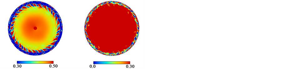
Figure 6. Contour of the helicity Hn in the (r, θ) plane at Γ = 0.0394, Re = 20000, z = 0.00984 and t = 300.
 (a)
(a)
 (b)
(b) (c)
(c)
Figure 7. Contour of the helicity Hn in plane at Γ = 0.0315 and Re = 10,000. (a) Flow in the (r, θ) plane at z = 0.0156; (b) Flow in the (θ, z) plane at r = 1.03; (c) Flow in the (r, z) plane at θ = 0.224 and t = 300.
position where these small vortices emerge is around the midplane in the axial direction (around z = 0.156 in Figure 7(b)). This axial position is different from the positions of the small vortices in Figure 4(b). This flow includes two Taylor vortices in the radial clearance. Their boundary is near the axial midplane and the flow is radially outward there (Figure 7(c)).
4. Flow Pattern Diagram
The Reynolds number dependences of the flow patterns at Γ = 0.0315, 0.0394 and 0.0472 are shown in Figure 8. In the diagrams, the blue lines and the red lines denote the lower bound and the upper bound of the Reynolds numbers that restrict the ranges where constant flow patterns appear. Please note that these lines are not plotted proportionally on the Reynolds number coordinate.
Figure 8(a) represents the diagram at Γ = 0.0315. When the Reynolds number (Re) is below 8200, a steady vortex flow with Taylor vortices appears in the radial clearance. In the present study, the lower limit of the Reynolds number for the onset of the Taylor vortices is not estimated because the axial lengths of the disk and the casing are too short to distinguish the Taylor vortices from the vortices intruded by the Ekman effect. The two layered bead-like flow is found at the Reynolds number from 8300 to 9700. The one layered bead-like flow in Figure 7(b) appears for 9800 £ Re £ 14000. The coexisting flow of the bead-like flow and the spiral structures do not appear at Γ = 0.0315. Instead the spiral structures are confirmed at least up to Re = 30,000.
The diagram at Γ = 0.0394 is shown in Figure 8(b). The lower critical value for the onset of the transitory bead-like flow is between 6400 and 6500. At the Reynolds number above 7400, the two layered bead-like flow appears. This flow does not transit to another flow pattern. For 10,000 £ Re £ 18,000, spiral structures elongating radially inward emerge and they coexist with the two layered bead-like flow. At 19,000 £ Re, the bead-like flow ceases and the spiral structures dominate the flow field.

Figure 8. Flow pattern diagrams at Γ = 0.0315 (a), 0.0394 (b) and 0.0472 (c).
The flow patterns at Γ = 0.0472 is depicted in Figure 8(c), where the disk is thin and the axial clearance is large. As the Reynolds number increases, the basic Taylor vortices and two layered bead-like flow appear. The bead-like flow coexists with the spiral structures for 8600 £ Re £ 17,000. The spiral structures expand at the Reynolds number beyond 18,000.
A systematic transition with the increase of the Reynolds number is found at all aspect ratios. First, Taylor vortices emerge in the radial clearance. Then, the bead-like flow appears, which has two layered structure consisting of small vortices near the end walls of the casing. At the higher Reynolds number, the flow has spiral structures around the disk tip. Some of the flow patterns such as the bead-like flow and the polygonal flow are also found in our experimental investigations [19] [20] . However, the transition mechanism is still unclear and it is one of the future studies.
The flow at Γ = 0.0394 contains the bead-like flow that has a vortex structure on one side of the end walls and transits to the polygonal flow. The bead-like and polygonal flow has an asymmetric structure in the axial direction and it appears at the relatively narrow range of the Reynolds number from 6500 to 7300. These flows are obtained from the numerical results of the governing equations. In experiment, these flows may be established, for example, by adjusting the acceleration ratio of the flow [27] .
At the aspect ratios of 0.0315, 0.0394 and 0.0472, the numerically estimated Reynolds numbers for the onset of the two layered bead-like flow are 8300, 7400 and 6900, respectively, and the Reynolds number for the onset of the spiral structures are 15,000, 10,000 and 8600, respectively. That is, as the aspect ratio increases and the axial clearance widens, the flow tends to be unstable. This is supported by the fact that the upper limit of the Reynolds number for the spiral structures, above which the flow turns out to be turbulent, also becomes smaller with the increase of the aspect ratio.
In the enclosed rotor-stator flow with no radial clearance, the Reynolds numbers for the onset of the first unsteady instability of spiral rolls are 70,000, 50,000 and 40,000 for the aspect ratios Γ of 0.0315, 0.0394 and 0.0472, respectively [3] . These values are an order of magnitude greater than the values for the two layered bead-like flow. Therefore, it can be said that the instabilities such as the Type I and Type II in the rotor-stator flow [22] are different from the instability of the flow in the present study. When the rotating disk and the casing are regarded as an inner cylinder and an outer cylinder, respectively, the flow around the rotating disk makes Taylor-Couette system governed by the centrifugal instability. In the Taylor-Couette system with infinite cylinders, the outer to inner radius ratio is used to estimate the critical Reynolds numbers for the onset of steady Taylor vortices [28] and wavy Taylor vortices [29] . The radius ratio in the present study is 0.894, and the critical Reynolds numbers for the steady and wavy Taylor vortices are about 1100 and 1200, respectively. This supports that the instability of the flow with the radial clearance originates from the centrifugal instability.
5. Conclusion
The flow around a rotating disk with axial and radial clearances has been investigated by a numerical approach for three sizes of disk thickness. The effect of the aspect ratio and the Reynolds number on the flow patterns, and the development scenario have been examined. The range of the Reynolds number is from 6000 to 30,000. When the Reynolds number is small, Taylor vortices appear in the radial clearance between the rotating disk tip and the side wall of the outer stationary casing. Then, the bead-like flow consisting of a series of small vortices around the disk appears. The two-layered bead-like flow has vortex structures on the both end walls of the casing. The critical Reynolds number for the onset of the two layered bead-like flow increases as the axial clearance becomes narrower. Other than this bead-like flow, two kinds of the bead-like flows are found. The one is the flow that has a vortex structure only on one side of the end walls of the casing. This flow tends to transit to a polygonal flow. This axially asymmetric flow is found at the Reynolds number lower than that for the two- layered bead-like flow. The other is the flow that includes a vortex structure along the axial midplane. The axial position where the bead-like flow appears is near the boundary of the vortices in the azimuthal plane, where the flow is radially outward. As the Reynolds number further increases, spiral structures are formed around the disk tip. The Reynolds number for the appearance of the spiral structures is an order of magnitude smaller than the Reynolds number for the onset of the spiral rolls in the rotor-stator flow.
Acknowledgements
The authors would like to thank Mr. Shota Hara for his helpful contributions to this work. This work was partly supported by JSPS KAKENHI Grant Number 15K05791.
Cite this paper
TakashiWatanabe,HiroyukiFurukawa,ShoheiFujisawa,SomaEndo, (2016) Effect of Axial Clearance on the Flow Structure around a Rotating Disk Enclosed in a Cylindrical Casing. Journal of Flow Control, Measurement & Visualization,04,1-12. doi: 10.4236/jfcmv.2016.41001
References
- 1. Launder, B., Poncet, S. and Serre, E. (2010) Laminar, Transitional and Turbulent Flows in Rotor-Stator Cavities. Annual Review of Fluid Mechanics, 42, 229-248. http://dx.doi.org/10.1146/annurev-fluid-121108-145514
- 2. Viaszzo, S., Poncet, S., Serre, E., Randriamampianina, A. and Bontoux, P. (2012) High-Order Large Eddy Simulation of Confined Rotor-Stator Flows. Flow Turbulence and Combustion, 88, 63-75. http://dx.doi.org/10.1007/s10494-011-9345-0
- 3. Schouveiler, L., Le Gal, P. and Chauve, M.P. (2001) Instabilities of the Flow between a Rotating and a Stationary Disk. Journal of Fluid Mechanics, 443, 329-350. http://dx.doi.org/10.1017/S0022112001005328
- 4. Savas, Ö. (1987) Stability of Bödewadt Flow. Journal of Fluid Mechanics, 183, 77-94. http://dx.doi.org/10.1017/S0022112087002532
- 5. Tuliska-Sznitko, E., Serre, E. and Bontoux, P. (2002) On the Nature of the Boundary Layers Instabilities in a Flow between a Rotating and a Stationary Disc. C.R.Mecanique, 330, 91-99. http://dx.doi.org/10.1016/S1631-0721(02)01432-8
- 6. Cros, A. and Le Gal, P. (2002) Spatiotemporal Intermittency in the Torsional Couette Flow between a Rotating and a Stationary Disk. Physics of Fluids, 14, 3755-3765. http://dx.doi.org/10.1063/1.1508796
- 7. Schouveiler, L., Le Gal, P., Chauve, M.P. and Takeda, Y. (1999) Spiral and Circular Waves in the Flow between a Rotating and a Stationary Disk. Experiments in Fluids, 26, 179-184. http://dx.doi.org/10.1007/s003480050278
- 8. Cros, A., Floriani, E., Le Gal, P. and Lima, R. (2005) Transition to Turbulence of a Batchelor Flow in a Rotor/stator Device. European Journal of Mechanics B/Fluid, 24, 409-424. http://dx.doi.org/10.1016/j.euromechflu.2004.11.002
- 9. Lopez, J.M., Marques, F., Rubio, A.M. and Avila, M. (2009) Crossflow Instability of Finite Bödewadt Flows: Transitions and Spiral Waves. Physics of Fluids, 21, 114107-1-9. http://dx.doi.org/10.1063/1.3262817
- 10. Poncet, S., Serre, é. and Le Gal, P. (2009) Revisiting the Two First Instabilities of the Flow in an Annular Rotor-Stator Cavity. Physics of Fluids, 21, 064106-1-8. http://dx.doi.org/10.1063/1.3156859
- 11. Spohn, A., Mory, M. and Hopfinger, E.J. (1998) Experiments on Vortex Breakdown in a Confined Flow Generated by a Rotating Disk. Journal of Fluid Mechanics, 370, 73-99. http://dx.doi.org/10.1017/S0022112098002092
- 12. Meeuwse, M., van del Schaaf, J. and Schouten, J.C. (2012) Multistage Rotor-Stator Spinning Disc Reactor. AIChE Journal, 58, 247-255. http://dx.doi.org/10.1002/aic.12586
- 13. Schouveiler, L., Le Gal, P. and Chauve, M.P. (1998) Stability of a Traveling Roll System in a Rotating Disk Flow. Physics of Fluids, 10, 2695-2697. http://dx.doi.org/10.1063/1.869793
- 14. Al-Shannag, M., Herrero, J., Humphrrey, J.A.C. and Giralt, F. (2002) Effect of Radial Clearance on the Flow between Corotating Disks in Fixed Cylindrical Enclosures. Transactions of ASME, Journal of Fluids Engineering, 124, 719- 727. http://dx.doi.org/10.1115/1.1487355
- 15. Hendriks, F. (2010) On Taylor Vortices and Ekman Layers in Flow-Induced Vibration of Hard Disk Drives. Microsystem Technologies, 16, 93-101. http://dx.doi.org/10.1007/s00542-008-0765-2
- 16. Washizu, T., Lubisch, F. and Obi, S. (2013) LES Study of Flow between Shrouded Co-Rotating Disks. Flow Turbulence and Combustions, 91, 607-621. http://dx.doi.org/10.1007/s10494-013-9494-4
- 17. Benjamin, T.B. and Mullin, T. (1981) Anomalous Modes in the Taylor Experiment. Proceedings of Royal Society of London, Series A, 377, 221-249. http://dx.doi.org/10.1098/rspa.1981.0122
- 18. Rucklidge, A.M. and Champneys, A.R. (2004) Boundary Effects and the Onset of Taylor Vortices. Physica D, 191, 282-296. http://dx.doi.org/10.1016/j.physd.2003.12.003
- 19. Watanabe, T. and Furukawa, H. (2010) Flows around Rotating Disks with and without Rim-Shroud Gap. Experiments in Fluids, 48, 631-636. http://dx.doi.org/10.1007/s00348-009-0785-4
- 20. Watanabe, T. and Furukawa, H. (2010) The Effect of Rim-Shroud Gap on the Spiral Rolls Formed around a Rotating Disk. Physics of Fluids, 22, Article ID: 114107. http://dx.doi.org/10.1063/1.3493640
- 21. Hara, S., Watanabe, T., Furukawa, H. and Endo, S. (2015) Effects of a Radial Gap on Vortical Flow Structures around a Rotating Disk in a Cylindrical Casing. Journal of Visualization, 18, 501-510. http://dx.doi.org/10.1007/s12650-015-0292-z
- 22. Séverac, é., Poncet, S. and Serre, é. (2007) Large Eddy Simulation and Measurements of Turbulent Enclosed Rotor- Stator Flows. Physics of Fluids, 19, Article ID: 085113. http://dx.doi.org/10.1063/1.2759530
- 23. Serre, E., Crespo Del Arco, E. and Bontoux, P. (2001) Annular and Spiral Patterns in Flows between Rotating and Stationary Discs. Journal of Fluid Mechanics, 434, 65-100. http://dx.doi.org/10.1017/S0022112001003494
- 24. Watanabe, T., Furukawa, H. and Nakamura, I. (2002) Nonlinear Development of Flow Patterns in an Annulus with Decelerating Inner Cylinder. Physics of Fluids, 14, 333-341. http://dx.doi.org/10.1063/1.1416498
- 25. Wu, S.C. (2009) A PIV Study of Co-rotating Disks Flow in a Fixed Cylindrical Enclosure. Experimental Thermal and Fluid Science, 33, 875-882. http://dx.doi.org/10.1016/j.expthermflusci.2009.03.008
- 26. Huang, R.F. and Hsieh, M.K. (2011) Phase-Resolved Flow Characteristics between Two Shrouded Co-Rotating Disks. Experiments in Fluids, 51, 1529-1547. http://dx.doi.org/10.1007/s00348-011-1168-1
- 27. Lim, T.T., Chew, Y.T. and Xiao, Q. (1998) A New Flow Regime in a Taylor-Couette Flow. Physics of Fluids, 10, 3233-3235. http://dx.doi.org/10.1063/1.869851
- 28. Koschmieder, E.L. (1993) Bénard Cells and Taylor Vortices. Cambridge University Press, Cambridge.
- 29. Cole, J.A. (1976) Taylor-Vortex Instability and Annulus-Length Effect. Journal of Fluid Mechanics, 75, 1-15. http://dx.doi.org/10.1017/S0022112076000098
Nomenclatures
hc: Casing thickness made dimensionless by Rd (-)
hd: Disk thickness made dimensionless by Rd (-)
hl, hu: Dimensionless lower and upper axial clearances, hl = hu = (hc − hd)/2 (-)
Hn: Normalized helicity (-)
p Pressure made dimensionless by ρ(Ω Rd)2 (-)
r: Radial coordinate made dimensionless by Rd (-)
rc: Inner radius of the casing made dimensionless by Rd (-)
Rd: Disk radius = 0.127 (m)
rd: Radius of the disk made dimensionless by Rd = 1.0 (-)
rs: Radius of the driving shaft made dimensionless by Rd (-)
t: Time made dimensionless by 1/Ω (-)
u: Velocity vector with components u, v and w made dimensionless by ΩRd (-)
z: Axial coordinate made dimensionless by Rd (-)
Γ: Aspect ratio = hu/rd (-)
ν: Kinematic viscosity of the working fluid (m2/s)
θ: Azimuthal angle (-)
ρ: Density of the working fluid (kg/m3)
Ω: Angular velocity of the disk and the driving shaft (1/s)
ω: Vorticity vector made dimensionless by Ω (-)