Journal of Minerals and Materials Characterization and Engineering
Vol.06 No.04(2018), Article ID:85904,17 pages
10.4236/jmmce.2018.64033
Development of Laser Fusion Printing Machine for Ceramic Teeth Crown
Risheng Zhang, Jialin Yang*, Zhiqun Wu, Xiaohui Tang, Wei Yu, Shaoxing Ma, Fang Ji
Institute of Machinery Manufacturing Technology, China Academy of Engineering Physics, Mianyang, China

Copyright © 2018 by authors and Scientific Research Publishing Inc.
This work is licensed under the Creative Commons Attribution International License (CC BY 4.0).
http://creativecommons.org/licenses/by/4.0/


Received: June 1, 2018; Accepted: July 8, 2018; Published: July 11, 2018
ABSTRACT
Since former president Obama of America put forward the concept of 3D printing or additive manufacturing, it had been putting into use rapidly and getting acceptance widely. In particular, metal additive manufacturing machines had been successfully applied with pilot demonstration in industry. However, the present metal additive manufacturing machines cannot be directly used in medical fields such as dental restoration because of some different requirements between industry and medical fields. In this case, this paper is aimed for the development of laser fusion printing machine (LFP), also being called as selective laser melting (SLM), for ceramic teeth crown in dental restoration business. Through the reasonable design and development of key components such as machinery unit, optical unit, electrical controlling unit, and software unit, and the integration, debugging, and optimization of the entire system, the laser fusion printing apparatus for dental restoration has been successfully developed. Key technologies such as machine structure design, optical unit design, electrical controlling system design, system software and process software have been overcome, on the basis of which, a lot of process experiments of medical titanium alloy materials were deeply carried out. At last laser fusion printing technology of titanium alloy was mastered, and titanium dental crown by laser fusion printing with relative density up to 97.37% was realized. After post treatment with porcelain, it was found that the laser fusion printed porcelain teeth with titanium alloy has good metal-ceramic bonding strength, which is equivalent to the quality of traditional porcelain teeth, which showed that laser fusion printing can meet the requirements of dental restoration business and has a broad market outlook.
Keywords:
Laser Fusion Printing, Additive Manufacturing, Dental Restoration, Selective Laser Melting

1. Introduction
Additive Manufacturing (AM), commonly known as 3D Printing, is the generic terms of all of the rapid prototyping or rapid manufacturing technologies which manufacture physical objects by means of adding materials directly on the basis of three-dimensional computer-aided-designed (CAD) model [1] - [8] . At present, AM has been widely using in the fields of defense, aeronautics & astronautics, biology and medicine, motor vehicle, mold, new material developing, individual customization, and so on, which could observably shorten the development period and manufacturing process attributed to its laminated manufacture principle which means that three-dimensional physical object with arbitrary complicated exterior shape or interior structure can be manufactured directly by means of three-dimensional CAD model without any tools and middle process [9] [10] [11] [12] .
Dental restoration is always an unavoidably realistic or potential problem for anyone because it is possible for teeth to damage in different degrees in our life. So to speak, dental restoration is c-losely related to everyone, which has the obvious characteristics of enormous quantity and wide aspect. So it goes without saying that the market scale of dental restoration is very large. At the same time, dental restoration field also urgently needs real personalized customization technologies because the dental characteristics are in endless variety for everyone. Now in dental restoration fields, the ceramic teeth restoration based on metal crown is still the main method, for which the key process, i.e. the manufacturing of ceramic teeth crown, is mainly made by the traditional process of investment casting. It belongs to lot manufacturing technologies and cannot realize the personalized customization, not only with low precision and long fabrication period but also with very low utilization factor of materials (about 30%) and large environment pollution. Laser fusion printing (LFP), also called as selective laser melting (SLM), is a typical additive manufacturing technology for metal materials with unique advantage of extensive material selection, high accuracy, good part performances and real ability to industrial application [13] - [18] . If the ceramic teeth crown is manufactured by use of LFP or SLM, the above-mentioned problems will be readily solved. Not only it has good precision and processing efficiency, but also its utilization factor of materials is very high (>90% at least). Most importantly, the veritable customization of ceramic teeth crown with individuation, digitization, precision and high efficiency will come true after using LFP technology. However, at present, most of LFP additive manufacturing machines are developed for industrial fields. Firstly, the laser power of this type of equipment is relatively high (about 500 W), so the diameter of laser focus is not very small, which leads to relatively low precision of parts. Secondly, its working size is usually large for industrial SLM additive manufacturing equipment, which leads to not only high initial acquisition cost but also high subsequent usage cost. At last, there are some special requirements in appearance and color for dental restoration machines, which result that the present industrial SLM machines have some limitations at an extent for the application in dental restoration fields. In response to this, it’s very necessary to develop special SLM machine for dental restoration fields according to related requirements so as to realize the customization of ceramic teeth crown with individuation, digitization, precision and high efficiency. In this paper, the development of key units including machinery design, powder spreading device, laser and scanning system, atmosphere controlling system, electro-controlling system, controlling software and process software, and the system integration and adjustment of all units had been well done.
2. General Design
Based on the characteristics of shape (complex freeform surface), structure (basically thin-walled structure) and dimensions (small overall size of ceramic teeth) and other factors of ceramic teeth, compared with industry-level laser fusion printing machine, three basic principles have been established for developing of laser fusion printing machine of ceramic teeth crown:
1) Single-mode fiber laser with lower laser power (no more than 200 W) are used to achieve smaller focusing accuracy, i.e., smaller focal spot diameter, thereby to improve printing accuracy and surface quality.
2) The use of a smaller printing range, on the one hand, to reduce the difficulty of manufacturing machine body, and on the other hand, also to be convenient to use a miniaturized and high-speed galvanometer scanning system, which ultimately reduces the overall manufacturing costs of machine, and at the same time considerably reduces the machine volume.
3) The appearance and color that match the characteristics of the dental restoration industry are used to make them consistent with the dental industry application scenario.
2.1. Design for Basic Function
According to the requirements of laser fusion printing process for dental metal, the laser fusion printing machine to be developed should have the following basic functions:
1) The output function of fiber laser with high quality to provide the continuous fiber laser with the single mode of TEM00 for melting metal powder layer rapidly and adequately.
2) The controlling function of printing atmosphere with high purity, i.e., the real-time dynamic controlling of oxygen content in the printing cabinet, to avoid high temperature oxidation.
3) The fine focusing and precise scanning function to focus the laser within a diameter of 0.1 mm and enable fast and accurate scanning of the specified area as needed.
4) Efficient and accurate powder-spreading function to ensure the smoothness and evenness of powder spreading which makes powder layer density as uniform as possible.
5) The precise lifting function of the building platform including the movement accuracy of the height direction and the levelness of the building platform are considered which require that the reverse gap is as small as possible, and the minimum movement resolution can reach 0.01 mm.
6) Accurate feeding function of feeding platform which can accurately supply powder according to the set powder thickness.
7) Coordinated system control function which need to develop a dedicated system control software to realize the coordinated actions of each unit system.
8) Planning function of scanning path which need to develop a dedicated process software to implement the setting, planning, and optimization of the laser fusion printing process.
9) Man-machine conversation function with a good user interface which can implement the functions such as file management, process controlling, parameter setting, failure alarm information display and diagnosis.
2.2. Design for Logical Structure
Generally, laser fusion printing machine for dental application includes two major parts: hardware and software. The hardware includes fiber laser, high-speed galvanometer, atmosphere control system, precision powder-spreading device, feeding cylinder, building cylinder, collecting cylinder, electronic control system, and other auxiliary system components. The software includes 3D modeling software, slice software, process planning software, system control software, and PLC embedded programs, which are shown in Figure 1.
2.3. Design for Layout and Appearance
The laser fusion printing machine includes two independent units: the host

Figure 1. Logical structure of the developed laser fusion machine.
machine and the atmosphere control system, which are placed separately. The host machine includes a machine body, a seal box, a working platform, an outer shell, a fiber laser, a high-speed galvanometer system, a powder spreading device, a feeding cylinder, a building cylinder, a collecting cylinder, and an electric control cabinet. The shell of host machine adopts streamlined design, and the material is made of ABS plastic sheet. According to the special requirements in medical fields, the main color of the equipment is sea grey and the decorative color is light blue, as shown in Figure 2.
The external dimension of host machine is approximately 1315 mm (length) × 920 mm (width) × 1780 mm (high). The size of sealed box is approximately 535 mm (length) × 550 mm (width) × 280 mm (height). The internal dimension of the building cylinder and feeding cylinder is approximately 120 mm (length) × 120 mm (width) × 210 mm (height), and the maximum printing range is 105 mm (length) × 105 mm (width) × 80 mm (height).
3. Subsystem Design
According to the basic functions and logical structure requirements of laser fusion printing machine to be developed, the design and development of subsystems such as optical unit, machinery unit, electronic control unit and software were carried out.
3.1. Option It Design
3.1.1. Option for Laser
At present, the most widely used dental metal materials are medical titanium alloys, and their main thermalphysic properties are shown in Table 1.
According to the material parameters in Table 1, the laser power required for fully melting titanium alloy can be estimated from Equations (1), (2), and (3) without considering heat dissipation, laser absorption efficiency, and enthalpy.
(1)


Figure 2. Layout and appearance of the developed laser fusion printing machine.

Table 1. Thermal physic parameters of titanium alloy.
(2)
(3)
Among them, c―material specific heat capacity, J/(g・K); mpowder―mass of powder within the laser spot, g; Tfusion and Tinitial―fusion point of titanium alloy powder and initial temperature, K; ΔHf―latent heat of fusion, kJ/mol; ρ―powder density, g/cm3; r―laser beam radius, um; h―powder bed thickness, mm; Plaser―the average output power of the laser, W; t―the time required to scan a spot size powder; v―scanning speed.
When the thickness of powder layer is h = 0.1 mm, 0.2 mm, and the focal spot diameter is 0.01 mm, for v = 2 m/s, 3m/s and 4m/s respectively, by Equations (1)-(3), the laser power required to fully melt the titanium alloy can be calculated, which were listed in Table 2.
From Table 2, it could be seen that when the scanning speed is 4 m/s, the laser power required for fusing the titanium alloy is about 167 W. In order to ensure that the titanium alloy powder is fully fused during the laser fusion printing process, the laser power is selected to be 200 W. For this purpose, continuous single-mode fiber laser is used. Its maximum laser power is 200 W with the wavelength of 1070 nm and the beam quality of M2 ≤ 1.10 (typically 1.05) which is cooled by air cooling. Its fiber output interface is a QBH interface.
3.1.2. Option for Scanner
Since the scanning range is small (100 mm × 100 mm), it is proposed to use the scanning first and then focusing (i.e., the pre-objective scanning method) to realize laser’s fine focusing and rapid & accurate scanning. After the laser beam is expanded, it is deflected by the scanning system, and then the laser beam is focused on the working plane (the building platform) via the f-theta focusing mirror, as shown in Figure 3. This solution is compact and inexpensive, and can ensure consistency of the focused spot size in the work plane without dynamic focusing.
Based on the maximum printing range and laser wavelength, a hurry SCANÒ III 14 galvanometer from Scan Lab company was used, with a f-theta focusing lens which focal length is f = 250 mm. In addition, in order to achieve fine focus, the laser beam needs to be expanded (2 - 8 times), and the input end of the beam expander must be able to match the QBH output end of the 200 W laser. For this purpose, the QBH beam expander manufactured by Ray tool company is used which result to the expanded beam diameter is with about 10mm. The minimum
Table 2. Laser power required for melting titanium alloys.
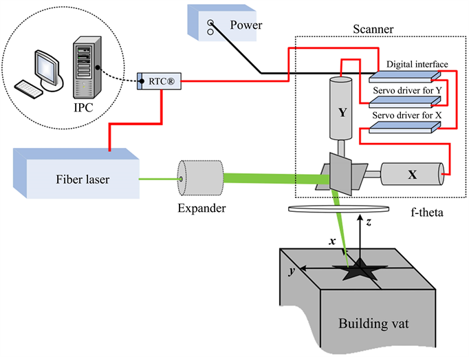
Figure 3. Schematic diagram of laser scanning focusing scheme.
focal spot diameter for laser focusing system can be determined by Equation (4).
(4)
Among them, S―Focal spot diameter (mm); λ―Laser wavelength (193 nm - 10.6 μm); f―Focal length (30 mm - 2000 mm); M2―Laser quality factor (Related to laser); k―Correction factor (The ideal value is 1.27, generally between 1.5 and 2.0); d―Beam diameter before focusing (generally 6 - 70 mm); For the laser scanning and focusing system described above, M2 = 1.05, the laser wave length λ is 1070 nm, and the focal length f is 250 mm, the minimum focal spot diameter in theory is about 40 um, by Equation (4).
3.2. Machinery Design
3.2.1. Body Design
In general, the entire machine tool is mainly divided into upper and lower parts. The upper part is a building cabinet, whit which subsystems such as a seal box, an optical fiber, a beam expanding mirror, a galvanometer, a field lens, and a powder-spreading device are installed. The lower part is a body part, which mainly includes a machine body, a working platform, a feeding platform, a building platform, laser, collecting cylinder and so on. The machine body is an inverted T-shaped structure and is an integral casting made of HT250. The top surface of machine body is used for supporting the working platform, and the vertical surface is the installation surface of two vertical axes (feeding cylinder and building cylinder). The hollow part of machine body is used to install the balancing weights, as shown in Figure 4.
3.2.2. Seal Box Design
The seal box provides a closed isolation environment for the laser fusion printing process, and is connected with the high-speed galvanometer, atmosphere control system, working platform, building cylinder, feeding cylinder, and collecting cylinder, as shown in Figure 5. The high-speed galvanometer is placed on the upper part of the sealing box through the mounting bracket. The sealing box has a round hole at the position corresponding to the center of building cylinder. The window mirror is fixed on the round hole through the flange so that the laser beam is incident on the working platform through the high-speed galvanometer system. The window mirror protects the galvanometer system from contamination as well as facilitates the sealing of printing cabinet. The seal box and the working platform are connected with sealing strips to ensure the airtightness of entire printing cabinet.
3.2.3. Working Platform Design
There are three square holes in the middle of the work platform, as shown in Figure 6. The left hole is used to install the feeding cylinder, the middle hole is used to install the building cylinder, and the right hole is used to install the collecting cylinder. A sealing groove is designed around the working platform to

Figure 4. Schematic diagram of the bed.

Figure 5. Seal box structure.

Figure 6. Schematic diagram of the working platform.
ensure the airtightness of the connection with the seal box. A rectangular hole is designed in front of the building cylinder to drain off the metal dust during processing.
3.2.4. Moving Unit Design
The laser fusion printing machine includes three mechanical motion units, namely the horizontal movement of the powder-spreading device (X axis) and the vertical movement of the feeding cylinder (Z1 axis) and the building cylinder (Z2 axis). According to the printing range and accuracy, the main performance of the three motion units is designed, as shown in Table 3. The drive unit of the feeding cylinder and the building cylinder adopts the standard movement module, which is simple and beautiful in appearance, with a protective cover and limit switches. The pitch of the Ball bearing guide screw is customized to 5 mm.
3.3. Controlling System Design
The overall control platform based on the IPC + open motion controller was designed to realize the coordination control of subsystem such as light, machine, electricity and gas for the entire equipment, as shown in Figure 7.
Table 3. The main performance indicators of the sports unit.

Figure 7. Overall control architecture.
The industrial personal computer (IPC) is used as the integrated control platform. Using the PCI slots, the motion control of the galvanometer mirror and the output control of the laser are realized through the RTC5 galvanometer control card. The control of the mechanical motion axes are realized by connecting the open Clipper motion control card and the actuators through the Ethernet port (Respectively, corresponding to the feeding cylinder, building cylinder and powder-spreading device), all of which are point to point control and use the digital drive mode, pulse + direction (Pulse + Dir), in order to improve anti-jamming capability. It uses the digital I/O interface to realize the start and stop function of the laser and the printing atmosphere control device. The power setting of the laser is realized through an industrial computer RS232 interface or an analog output port, as shown in Figure 8.
3.4. Control Software Development
3.4.1. Module Design
The control system software is divided into four subsystems according to the modular design concept: human-computer interaction subsystem, scanning galvanometer control subsystem, powder-spreading mechanism subsystem and laser control subsystem, as shown in Figure 9.
3.4.2. Architecture Design
From a system point of view, on the basis of based on the selected hardware system, a hierarchical software architecture is established, which is divided into four layers: a hardware interface layer, a control logic layer and a human-machine interface layer, as shown in Figure 10. The hardware interface layer provides a common interface for the control logic layer and the human-machine interface layer. According to the communication protocol used by the hardware platform and the control system platform, the hardware interface layer realizes the packaging of the clipper motion controller and the RTC5 galvanometer controller. The control logic and hardware are combined into tight functional modules, which are divided into control logic layer and human-machine interface layer. The control logic layer is realized through logic control PLC program and motion process control NC program. The human-machine interface layer provides the interactive interface between logical control layer and user. It accepts external data and command input, and displays system working data and running status.
3.4.3. Program Development
Development of human-machine interface programs, built-in process programs and PLC programs was carried out. The man-machine interface program mainly includes a startup interface, an automatic printing interface (Figure 11), a
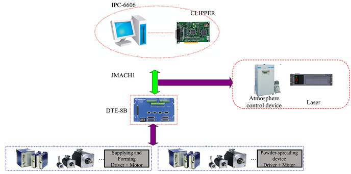
Figure 8. Three-axis point to point control hardware structure.

Figure 9. Software function block diagram.
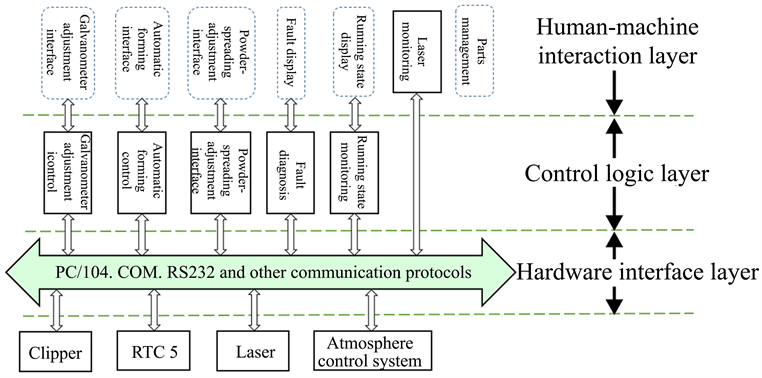
Figure 10. Software hierarchy diagram of control system.
galvanometer adjustment interface, a powder-spreading interface, and other auxiliary operation interface. The built-in process program is designed and developed using the motion program language of the clipper controller. It is invoked through human-computer interaction software to realize the motion control of each moving axis (building cylinder, feeding cylinder, and powder-spreading mechanism), mainly including automation powder-spreading program, and quick reset program and limited position controlling program of the powder spreading mechanism. The PLC program has been set in the clipper controller to implement functions such as emergency stop and reset of the machine.

Figure 11. Automatic forming interface.
3.5. Process Software Development
3.5.1. Module Design
The laser fusion printing process software system for dental applications is mainly composed of STL model display module, slice processing module, scanning path generation module, process parameter setting module, printing files processing module, command processing module and process simulation module. The software interface of main function module is shown in Figure 12.
3.5.2. Scanning Strategy Design
This software has designed a composite scanning strategy being composed of contour offset scanning and inner partition scanning. That is, the inner and outer contours of a layer are filled with contour offsets, and the inner areas are block-like scanning symmetrically by laser. In this scanning mode, the advantages of high scan accuracy of contour offset scanning and high efficiency and stability of partition scanning can be fully utilized. The strategy is shown in Figure 13.
4. Assemblage and Adjustment
4.1. Integration and Adjustment of Machinery Units
The assemblage and adjustment of machinery components were carried out, which mainly including level adjustment of the basic components, adjustment of the movement accuracy of the building cylinder and feeding cylinder, optimization of the movement precision of the powder-spreading device, installation of the galvanometer mirror, installation and adjustment of the fiber laser, adjustment of allaxis’s limit switch, the out shell’s installation and adjustment, and the installation and adjustment of other mechanical components.
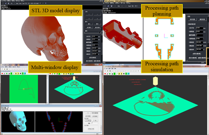
Figure 12. Effect of software function modules.
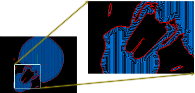
Figure 13. Composite scanning strategy considering accuracy and efficiency.
4.2. Integration and Adjustment of Electrical Controlling Units
The integration and test of all electrical controlling components was conducted, mainly including the improvement and production of electrical control system, weak electric signal processing and electrical safety protection system, the signal connection and test of controlling system with each movement axis, the signal connecting and adjustment of laser system with controlling system, the controlling parameters optimization of every motion axis, the joint debugging of allaxis’s motion and signal test and improvement of all I/O points.
4.3. Integration and Adjustment of System Software
Integration and debugging of system control software with hardware system of the developed machine was carried out, including the logic control of the machine's operation panel, the PID adjustment of three movement axes in the powder-spreading process, the automatic and manual controling of the powder-spreading mechanism, the hardware system integration and debugging of laser fusion printing machine body and the integration of galvanometer mirror’s control software with system software.
4.4. Test and Evaluation for Whole System
After completing the integration and test of all of hardware and software, a test and evaluation of full system was carried out, mainly including axis motion function test, program operation test, laser control test, emergency stop control test, instructor light control tests, and the mechanical axes motion accuracy test. The test results of the main performance of the laser fusion printing machine showed in this paper are shown in Table 4.
5. Laser Fusion Printing Results
The 3D printing process test of titanium alloy material (TC4) was carried out using the self-developed laser fusion printing machine for ceramic dental application. When the main process parameters are as followed: laser power = 180 W, scanning speed = 200 mm/s, scanning space = 0.1 mm, layer thickness = 0.1 mm, tool compensation = 0.1 mm, 3D printing of titanium alloy samples can be achieved with a relative density of 97.37%.
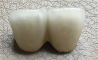
The laser fusion printing accuracy is closely related to tool compensation parameter and the proportion coefficient (i.e., the X-axis and Y-axis’s magnification factors). By optimizing the tool compensation parameter and the galvanometer ratio coefficient, the accuracy of laser fusion printing is significantly improved. When the tool compensation parameter is 0.1mm, and the proportion coefficient is X = 0.9975062, Y = 0.9950249, the printing accuracy of the titanium alloy material is about ±0.02 mm, which means the additive manufacturing, i.e. customization fabrication of the titanium alloy ceramic teeth crown by laser fusion printing could be realized (Figure 14(a)). Figure 14(b) is the ceramic teeth crown after porcelain decorating.
6. Conclusion
According to the market characteristics of the dental prosthetics industry, through the rational design and development of key components such as mechanical units, optical units, electronic control units, and software units, as well as the integration and optimization of the whole system, the laser fusion printing
Table 4. Technical specifications of the developed machine.
 (a)
(a)
 (b)
(b)
Figure 14. Laser fusion printed titanium teeth crown.
machine for dental restoration was successfully developed. The equipment has overcome key core technologies such as machine body structure design, optical unit design, electrical controlling system design, and the development of system software and process software. Based on this, a number of in-depth laser fusion printing processing experiments for medical titanium alloy materials was conducted. Thus, the laser fusion printing technology forTC4 titanium alloy material have been initially mastered, and the individuation manufacturing of titanium-based ceramic teeth crown by laser fusion printing with a relative density of 97.37% has been realized. After post treatment with porcelain, it was found that the laser fusion printed titanium-based ceramic teeth crown has good metal-ceramic bonding strength, which is equivalent to the quality of traditional casting-based ceramic teeth crown. It is shown that the laser fusion printed ceramic teeth crowns are able to meet the requirements of dental restoration and have a broad market prospect. At the same time, some improvement such as the optimization of building vat an feeding vat, seal ability of building cabinet, controlling software and process software for the developed LFP machine will be carried out in the near future for better acceptance.
Funding
Supported by the key R&D program of Sichuan province with the granted number of 2017GZ0076.
Cite this paper
Zhang, R.S., Yang, J.L., Wu, Z.Q., Tang, X.H., Yu, W., Ma, S.X. and Ji, F. (2018) Development of Laser Fusion Printing Machine for Ceramic Teeth Crown. Journal of Minerals and Materials Characterization and Engineering, 6, 465-481. https://doi.org/10.4236/jmmce.2018.64033
References
- 1. Rochusa, P., Plesseriaa, J.Y., Van, M., et al. (2007) New Applications of Rapid Prototyping and Rapid Manufacturing Technologies for Space Instrumentation. Acta Astronautica, 61, 352-359. https://doi.org/10.1016/j.actaastro.2007.01.004
- 2. Simchi, A. (2006) Direct Laser Sintering of Metal Powder: Mechanism, Kinetics and Microstructural Feature. Materials Science and Engineering A, 428, 148-158. https://doi.org/10.1016/j.msea.2006.04.117
- 3. Yang, J.L. (2017) Selective Laser Melting Additive Manufacturing of Advanced Nuclear Materials V-6Cr-6Ti. Materials Letters, 209, 268-271. https://doi.org/10.1016/j.matlet.2017.08.014
- 4. Yang, J.L., Ouyang, H.W., Xu, C. and Wang, Y. (2010) Development of Direct Metal Laser Fabricating Machine. Materials Technology, 25, 49-55. https://doi.org/10.1179/106678509X12519036707953
- 5. Yang, J.L., Ouyang, H.W. and Wang, Y. (2010) Direct Metal Laser Fabrication Machine Development and Experimental Work. The International Journal of Advanced Manufacturing Technology, 46, 1133-1143. https://doi.org/10.1007/s00170-009-2174-9
- 6. Gu, D.D., Shen, Y.F., Fang, S.Q., et al. (2007) Metallurgical Mechanisms in Direct Laser Sinte-Ring of Cu-CuSn-CuP Mixed Powder. Journal of Alloys and Compounds, 438, 184-189. https://doi.org/10.1016/j.jallcom.2006.08.040
- 7. Wang, X.C., Laoui, T. and Bonse, J. (2002) Direct Selective Laser Sintering of Hard Metal Powders: Experimental Study and Simulation. The International Journal of Advanced Manufacturing Technology, 19, 351-357. https://doi.org/10.1007/s001700200024
- 8. Badrossamay, M. and Childs, T.H.C. (2007) Further Studies in Selective Laser Melting of Stainless and Tool Steel Powders. International Journal of Machine Tools & Manufacture, 47, 779-784. https://doi.org/10.1016/j.ijmachtools.2006.09.013
- 9. Yang, J.L., Ouyang, H.W., Xu, C. and Wang, Y. (2012) Top Surface Quality Research For Direct Metal Laser Fabrication. Rapid Prototyping Journal, 18, 4-15. https://doi.org/10.1108/13552541211193458
- 10. Kruth, J.P., Froyen, L., Van Vaerenbergh, J., et al. (2004) Selective Laser Melting of Iron-Based Powder. Journal of Materials Processing Technology, 149, 616-622. https://doi.org/10.1016/j.jmatprotec.2003.11.051
- 11. Simchi, A., Rota, A. and Imgrund, P. (2006) An Investigation on the Sintering Behavior of 316L and 17-4PH Stainless Steel Powders for Graded Composites. Materials Science and Engineering: A, 424, 282-289. https://doi.org/10.1016/j.msea.2006.03.032
- 12. Gu, D.D., Shen, Y.F. and Meng, G.B. (2009) Growth Morphologies and Mechanisms of TiC Grains during Selective Laser Melting of Ti-Al-C Composite Powder. Materials Letters, 63, 2536-2538. https://doi.org/10.1016/j.matlet.2009.08.043
- 13. Gebhardt, A., Schmidt, F.M., Hotter, J.S., Sokalla, W. and Sokalla, P. (2010) Additive Manufacturing by Selective Laser Melting the Realizer Desktop Machine and Its Application for the Dental Industry. Physics Procedia, 5, 543-549. https://doi.org/10.1016/j.phpro.2010.08.082
- 14. Takaichi, A., Suyalatu, Nakamoto, T., Joko, N., Nomura, N., et al. (2013) Microstructures and Mechanical Properties of Co-29Cr-6Mo Alloy Fabricated by Selective Laser Melting Process for Dental Applications. Journal of the Mechanical Behavior of Biomedical Materials, 21, 67-76. https://doi.org/10.1016/j.jmbbm.2013.01.021
- 15. Cardaropoli, F., Alfieri, V., Caiazzo, F. and Sergi, V. (2012) Manufacturing of Porous Biomaterials for Dental Implant Applications through Selective Laser Melting. Advanced Materials Research, 535-537, 1222-1229. https://doi.org/10.4028/http://www.scientific.net/AMR.535-537.1222
- 16. Lu, Y., Wu, S., Gan, Y., Li, J. and Zhao, C. (2015) Investigation on the Microstructure, Mechanical Property and Corrosion Behavior of the Selective Laser Melted CoCrW Alloy for Dental Application. Materials Science & Engineering: C, 49, 517-525. https://doi.org/10.1016/j.msec.2015.01.023
- 17. Dickens, P. and Khan, M. (2014) Selective Laser Melting (SLM) of Pure Gold for Manufacturing Dental Crowns. Rapid Prototyping Journal, 20, 471-479.
- 18. Di Giacomo, G.A., da Silva, J.V., da Silva, A.M., Paschoal, G.H., Cury, P.R. and Szarf, G. (2012) Accuracy and Complications of Computer-Designed Selective Laser Sintering Surgical Guide for Flapless Dental Implant Placement and Immediate Definitive Prosthesis Installation. Journal of Periodontology, 83, 410-419. https://doi.org/10.1902/jop.2011.110115