Open Journal of Energy Efficiency
Vol.04 No.03(2015), Article ID:58989,7 pages
10.4236/ojee.2015.43005
Case Study of Solar Power Producing Efficiency from a Photovoltaic System
Ching-Lung Lin
Department of Electrical Engineering, Mingshin University of Science and Technology, Hsin-Chu, Taiwan
Email: cll@must.edu.tw
Copyright © 2015 by author and Scientific Research Publishing Inc.
This work is licensed under the Creative Commons Attribution International License (CC BY).
http://creativecommons.org/licenses/by/4.0/


Received 24 June 2015; accepted 21 August 2015; published 24 August 2015
ABSTRACT
To study the efficiency increasing of electric energy generation in the Photovoltaic System is concentrated on this paper. There are four cases to improve the efficiency of power producing from the Photovoltaic System. This article not only describes the differences of facilities before and after the proposal, but also evaluates the electric energy generation efficiency and improved results for each proposal. Finally, the better efficiency of all improving ways is analyzed to get into conclusions in order to provide further improvement and reference for the industry in the future. Overall, these proposed methods can improve the efficiency of solar photovoltaic electric energy generation in about 30.18%.
Keywords:
Solar Cell, Photovoltaic, Tracking Device, Inverter

1. Introduction
Sun is a completely unpolluted natural resource, and sunshine illuminates all over the world. It is a sustainable energy resource which cannot be monopolized. Each year, the quantity of solar energy irradiating on the earth is more than the need of human consumption. If it is possible to convert this huge and unpolluted energy for application, then the problem in the shortage of energy for human can be solved. In current regenerated energy resources, photovoltaic is the best technique developed so far and is the most potential energy resource. Photoelectric effect is to pass solar energy through solar-cell to transfer it into electric power. This kind of photo- electric transformation is mainly with the help of photoelectric effect of semiconductor elements to proceed. It is applied to supply power to space station, artificial satellite, and remote area. It is also used to setup solar power plant and merge into power generation [1] - [3] .
2. Generation of Photovoltaic System
The power production device involved is the solar cell. Modules and consequently arrays are made by series and parallel connection of such solar cells. This solar cell is a p-n junction diode that converts light energy from the sun into electrical energy. The current and voltage thus produced have a non-linear relationship. The power thus available from a solar cell peaks at a particular operating voltage. This peak power and the corresponding operating voltage keep varying with changing insolation and temperature conditions [4] .
2.1. Operational Theorem of Solar-Cell
Electrons of p-type semiconductor and positive electric charges of n-type semiconductor are attracted with each other. The blocking layer is formed in the positive-negative neutralized area at the p-n junction. If there is light illuminating on the p-n junction, free electron will be excited and flowed into n-type semiconductor while positive electric charge is moved to p-type semiconductor. Furthermore, electric potential force is produced. If it is connected with load, then there will be electric current moving on it. In simplicity, the theorem of generating electric power from photovoltaic is to utilize the solar-cell to directly transform photo energy into the other kind of electric energy by absorbing ultraviolet rays with 0.2 - 0.39 μm wavelength. The operational theorem of a solar-cell is shown as Figure 1.
Solar power is a kind of free and unlimited resource on earth which would not waste our natural resources pollutes our environment and cause to greenhouse effect. Photovoltaic module must accept any strict outdoor environment in the world. Otherwise, the life of this product is also the longest in the world, over 25 years. Due to the world values of protecting the environment, solar industry is developing rapidly and becoming popular. Figure 2 shows the fundamental solar power generation structure of photovoltaic system.
2.2. Comparison of Solar Cell
The materials of commercial solar cells, they can be classified into following types: Single Crystal Silicon, Polycrystal Silicon, Amorphous Silicon, GaAs, InP, CdS, CdTe, CuInse, CuInGaSe and currently researching Dye-Sensitized Nanocrystalline Solar Cell [5] and Organic Solar Cell and so on as indicated in Table 1. The

Figure 1. Operational theorem of a solar-cell.

Figure 2. Shows the fundamental solar power generation structure of photovoltaic system.

Table 1. Comparison of solar cell.
Data resources: solarpv.itri.org.tw, Green Energy and Environment Research Laboratories of Industrial Technology Research Institute (ITRI).
developed technique of Silicon Crystalline Solar-cell is more mature than others. Its efficiency of power genera- tion is also perfectly stable. It always is the main force of solar cells. On one occasion, since the price of Silicon material is raising the other PC techniques likes membrane types have chances to scurry. The merit of the membrane type lies in being able to combine with glass building materials. This will make it to become the large scale membrane-type solar-cell and also be able to absorb sunlight from different angles. Unlike the silicon crystalline type, it must face south to setup the best angle in Taiwan. However, the efficiency of power genera- tion in the membrane type is not as good as the silicon crystalline type, and there are many technical problems needed to be conquered. Therefore, actual applications are still mainly used the silicon crystalline type solar cells.
3. Structure of Photovoltaic System
In this case, the photovoltaic system has been installed at Pingtung district, Taiwan. The plane configuration of the system is indicated in Figure 3. Equipments include: solar-cell arrays, the extended-height type of the module supported frame, junction boxes of direct current, Inverters, switch boxes of alternating current, voltage step-up transformers, high-voltage distributors, the wholesale electric meter and so on. The array of solar-cell modules (or referred to as the solar panel) should be put up on the 3.2-meter rack to face south with 10 degrees of the angle of elevation. Total capacities of electric power production is 403.26 kW (1716 slices of solar-cell module × 235 Watt/slice). According to the regulation of Item III Rule (2) in “Technique Essentials for Merging the Power Generating System of Renewable Energy with Taiwan Power Company (Taipower)”, the power generating equipment with total capacity between 100 kW and 10,000 kW should be transfer to 11.4 kV high- voltage feeding system of Taipower.
The ways of setting up this photovoltaic system and its environmental conditions are as followings: the solar- cell arrays are arranged from North to South as the first row (PV-1-PV-4) and the fourth row (PV-13-PV-17). The transformer station of the photovoltaic system is set up as indicated in Figure 4.
The block diagram of the solar-cell array, transformers, and the circuits of protection device is described in Figure 5. It escaped time can be coordinated with the Taipower.
4. Improved Cases for Increasing Energy Efficiency
The power production efficiency of solar cell is about 13% to 17%. Therefore, this paper suggests four cases to improve and increase the efficiency of power generation from the photovoltaic system.
4.1. Increasing the Efficiency from the Amorphous Transformer
The amorphous transformer has characteristics which are low iron loss and low noise, this system changes the 500 kVA traditional high-efficient transformer of the original design to an amorphous, low iron loss and ultrahigh-efficient transformer. The iron loss of the originally adopted traditional high-efficient transformer is 1026 W, however, the iron loss of the amorphous, low iron loss and ultrahigh-efficient transformer is only 220 W. Calculating the wastage power (iron loss) of the traditional high-efficient transformer is as follows:

Figure 3. Power plane configuration of the photovoltaic system.

Figure 4. The transformer station in the photovoltaic system.
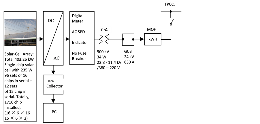
Figure 5. Block diagram of the solar-cell array, transformer and protection device.
![]() (1)
(1)
However, the wastage power (iron loss) of the amorphous, low iron loss and ultrahigh-efficient transformer is:
![]() (2)
(2)
Using the amorphous transformer, the saving amount of wastage power from iron losses for each year totally is:
![]() (3)
(3)
The year average quantity of power generation set up by this system is 647,636 kWH/year, and which is calculated as:
![]() (4)
(4)
The improved efficiency increased by using the amorphous transformer is:
![]() (5)
(5)
4.2. Increasing the Efficiency by Uninstalling the Anti-Reverse Diode
Advantages of uninstalling the anti-reverse diodes are:
1) Solves the heat-radiating problem while diodes are functioning with giving out heat;
2) Avoids small animals to come to warm themselves and to cause the short-circuit problem;
3) Decreases the wastage of promoting the efficiency of power generation from photovoltaic.
This system is originally installed with 96 anti-reverse diodes. If the quantity of daily equivalent sunshine is estimated to be 4.4 hours, then the wasting power reduced daily by removing the anti-reverse diodes is:
![]() (6)
(6)
Wasting power by a year is:
![]() (7)
(7)
The year average quantity of power generation set up by this system is 647,636 kWH/year indicated in Equation (4). The improved efficiency increased by uninstalling the anti-reverse diode is 0.1%. This is shown as follows:
![]() (8)
(8)
4.3. Increasing the Efficiency by a Sprinkling Water
The geographic location of Taiwan is belonged to the subtropical zone. Especially, Taiwan is full of sunshine, though the temperature is very high. The environmental condition is very suitable to develop photovoltaic energy. Consequently as long as we improve the construction of PV system, increase height of the PV construction, support very large space to get very adequate airflow, and the temperature of PV modules could be kept at about 55˚C. The distance from PV modules to ground must be 3 meters high at least. We can have infinite future of developing Photovoltaic System [5] .
In the way of choosing the cooling system for the photovoltaic system, not only increasing economic efficiency of power production, but also getting higher interest rate to make more income and reduce your investment during. The more intensity of sunshine is the more quantity of power generation from PV system. Since the solar-cell module is with the property of negative temperature coefficient, as the temperature of the module is rising, the efficiency of power generation is decreasing gradually [6] - [9] . For this reason, this study established the Cooling System by Sprinkling Water on May, 2011 to reduce the temperature of modules. Because dust and squalidness on the surface of solar cells are also factors of affecting the efficiency of power generation, establishing the water-sprinkling system can reduce the temperature of modules and can clean surfaces of panels as well to increase the efficiency of power generation.
According to “Planning Method and Life-Cycle Cost Analysis for Large-Scale Photovoltaic System” [10] , it provides the average temperature on the back side of the module for each month in Taiwan. The obtained power results are estimated and shown in Table 2.
Table 2. Average temperature on the back side of the module and power results for each month in Taiwan.
Usually, the practical operation is to sprinkle water until the temperature is rising to the highest point. When it is down to 40˚C, then stop sprinkling water. Therefore, the efficiency can be increase to 5.8%/2 = 2.9% by using the theory of calculating the triangle area.
4.4. Increasing the Efficiency by a Tracking System
The tracking device for solar cell with a sensor which is composed of four photo-resistors surrounding a sunshade to represent east, west, south and north. The resistance of photo-resistor will vary under solar irradiance such that the position of the sun can be determined by comparing circuit based on which the AC motor can be driven to allow perpendicular incident angle of sunlight onto the solar cell. This way the solar illumination can be improved and power generation efficiency can be enhanced. The tracking system is shown as Figure 6 [11] [12] .
There are two solar cell testing devices to receive illumination data in the same testing environment. Table 3 shows that the non-tracking illumination data received from the solar cell. Table 4 shows the tracking illumination data received from another solar cell. The data were recorded from 6 am to 17 pm, from morning to evening. The solar photovoltaic system with a tracking device, the solar illumination can be improved and power generation efficiency can be enhanced. When the solar illumination on solar cell was improved, that the solar voltage (v) and the solar current (A) values also to be increased. So, the total power producing efficiency is getting higher. According to the dada from Table 3 and Table 4, the record date of solar cell, the power producing is accumulated during sunshine time. The daily improving power producing is calculated by Equation (9). (Exclude the power used of the tracking device).
![]() (9)
(9)
Experiment results show that the proposed all weather tracking device improves the tracking operation precision and reliability of solar power generation system, improves the photovoltaic system transformation efficiency [12] . Figure 7 shows the data comparison of two solar photovoltaic systems.
The increasing power producing is shown at the bottom line of Table 3 and Table 4. The energy generation efficiency is increased 26.08% every day, shown as Equation (10).
![]() (10)
(10)
Although the tracking device of solar photovoltaic system increases 26.08% of energy generation efficiency, it must base on a shining day. If it is a windy day, the tracking device must be stop. The wind will damage the tracking device.
5. Conclusions
The geographic location of Taiwan is belonged to the subtropical zone. Especially, the south district of Taiwan is full of sunshine. The environmental condition is very suitable to develop photovoltaic. Consequently, as long as we improve moreover on the utilizing technology of solar energy, we can have infinite future of developing photovoltaic.
Cases adopted by this study to improve and increase the efficiency of power producing from the photovoltaic system are listed in the followings:
1) Use the amorphous transformer―The improved efficiency increased 1.1%.
2) Remove the anti-reverse diode―The improved efficiency increased 0.1%.
3) Establish the cooling system by sprinkling water―The improved efficiency increased 2.9%.
4) Solar cell with a tracking device―The improved efficiency increased 26.08%.

Figure 6. The tracking device for a solar cell.

Figure 7. The data comparison of two solar photovoltaic systems.
Table 3. The power producing from the non-tracking solar photovoltaic system.
Table 4. The power producing from the tracking solar photovoltaic system.
Four improving cases of power producing from the photovoltaic system of this study totally increased the efficiency to around 30.18%. This is obviously increasing the transforming efficiency for the power generation from photovoltaic, but the result of the solar cell with a tracking device must depend on the weather.
Cite this paper
Ching-LungLin, (2015) Case Study of Solar Power Producing Efficiency from a Photovoltaic System. Open Journal of Energy Efficiency,04,45-52. doi: 10.4236/ojee.2015.43005
References
- 1. Yang, J.-D. (2009) Solar Cell Materials. Wu-Nan Book Inc.
- 2. Baechler, M.C., Gilbride, T., Ruiz, K., Steward, H. and Love, P.M. (2007) High-Performance Home Technologies Solar Thermal & Photovoltaic Systems. NREL/TP-550-41085 PNNL-16362.
- 3. Grätzel, M. (2001) Photoelectro-Chemical Cells. Nature, 414, 338-344.
http://dx.doi.org/10.1038/35104607 - 4. Koutroulis, E., Kalaitzakis, K. and Voulgaris, N.C. (2001) Development of a Microcontroller-Based, Photovoltaic Maximum Power Point Tracking Control System. IEEE Transactions on Power Electronics, 16, 46-54.
http://dx.doi.org/10.1109/63.903988 - 5. Lin, C.-L., Shih, C.-H., Lin, C.-F. and Chen, K.-J. (2014) Study of Constructions for the Photovoltaic System to Increase the Economic Efficiency of Energy Generation. Proceedings of the 2014 International Conference on E-Busi-ness Engineering, China, 207-212.
http://dx.doi.org/10.1109/icebe.2014.43 - 6. King, D.L. (1996) Photovoltaic Module and Array Performance Characterization Methods for All System Operating Conditions. Proceeding of NREL/SNL Photovoltaics Program Review Meeting, Lakewood, AIP Press, New York.
- 7. Chen, S.-C. (2006) A Study of Photovoltaic /Thermal Solar Collector. Lee Ming Journal, 18, 11-16.
- 8. Wang, S.-F. (2009) The Strategies of Feed-In Tariffs in Building Integrated Photovoltaic (BIPV). Degree Thesis of Graduate Institute of Construction Engineering and Management, National Central University.
- 9. Nishiokaa, K., Hatayamaa, T., Uraokaa, Y., Fuyukia, T., Hagiharab, R. and Watanabec, M. (2003) Field-Test Analysis of PV System Output Characteristics Focusing on Module Temperature. Solar Energy Materials & Solar Cells, 75, 665-671.
http://dx.doi.org/10.1016/S0927-0248(02)00148-4 - 10. Chan, C.-C. (2009) Planning Method and Life-Cycle Cost Analysis for Large-Scale Photovoltaic System. Degree Thesis of Graduate Institute of Civil Engineering, National Taiwan University.
- 11. Lu, C.-L., Wang, J.-M., Shiang, Y.-H., Cheng, C.-Y. and Cheng, C.-C. (2011) Fast-Tracking Solar System with Dynamic Computer Monitoring. The 32nd Symposium on Electrical Power Engineering, 334-338.
- 12. Xu, X.L., Liu, Q.S. and Zuo, Y.B. (2010) A Study on All-Weather Flexible Auto-Tracking Control Strategy of High-Efficiency Solar Concentrating Photovoltaic Power Generation System. 2nd WRI Global Congress on Intelligent Systems (GCIS), 2, 375-378.
http://dx.doi.org/10.1109/gcis.2010.70