International Journal of Clean Coal and Energy
Vol.3 No.1(2014), Article ID:43332,12 pages DOI:10.4236/ijcce.2014.31001
Investigation of Low Rank Coal Gasification in a Two-Stage Downdraft Entrained-Flow Gasifier
Energy Conversion & Conservation Center, University of New Orleans, New Orleans, USA
Email: xlv@uno.edu, twang@uno.edu
Copyright © 2014 Xijia Lu, Ting Wang. This is an open access article distributed under the Creative Commons Attribution License, which permits unrestricted use, distribution, and reproduction in any medium, provided the original work is properly cited. In accordance of the Creative Commons Attribution License all Copyrights © 2014 are reserved for SCIRP and the owner of the intellectual property Xijia Lu, Ting Wang. All Copyright © 2014 are guarded by law and by SCIRP as a guardian.
Received November 15, 2013; revised December 17, 2013; accepted January 25, 2014
Keywords: Low-Rank Coal; Two-Stage Coal Feeding Gasification; Gasification Simulation; Clean Coal Technology
ABSTRACT
Low-rank coal typically contains more inherent moisture, high alkali metals (Na, K, Ca), high oxygen content, and low sulfur than high-rank coal. Low-rank coal gasification usually has lower efficiency than high-rank coal, since more energy has been used to drive out the moisture and volatile matters and vaporize them. Nevertheless, Low-rank coal comprises about half of both the current utilization and the reserves in the United States and is the largest energy resource in the United States, so it is worthwhile and important to investigate the low-rank coal gasification process. In this study, the two-stage fuel feeding scheme is investigated in a downdraft, entrained-flow, and refractory-lined reactor. Both a high-rank coal (Illinois No.6 bituminous) and a low-rank coal (South Hallsville Texas Lignite) are used for comparison under the following operating conditions: 1) low-rank coal vs. high-rank coal, 2) one-stage injection vs. two-stage injection, 3) low-rank coal with pre-drying vs. without pre-drying, and 4) dry coal feeding without steam injection vs. with steam injection at the second stage. The results show that 1) With predrying to 12% moisture, syngas produced from lignite has 538 K lower exit temperature and 18% greater Higher Heating Value (HHV) than syngas produced from Illinois #6. 2) The two-stage fuel feeding scheme results in a lower wall temperature (around 100 K) in the lower half of the gasifier than the single-stage injection scheme. 3) Without pre-drying, the high inherent moisture content in the lignite causes the syngas HHV to decrease by 27% and the mole fractions of both H2 and CO to decrease by 33%, while the water vapor content increases by 121% (by volume). The low-rank coal, without pre-drying, will take longer to finish the demoisturization and devolatilization processes, resulting in delayed combustion and gasification processes.
1. Introduction
Gasification is the process of converting various carbonbased feedstocks to clean synthetic gas (syngas), which is primarily a mixture of hydrogen (H2) and carbon-monoxide (CO) with minor methane (CH4) and inert nitrogen gas, through an incomplete combustion. Feedstock is partially combusted with oxygen and steam at high temperature and pressure with only less than 30% of the required oxygen for complete combustion being provided. The syngas produced can be used as a fuel, usually for boilers or gas turbines to generate electricity, or can be used to make a synthetic natural gas, hydrogen gas or other chemical products. The gasification technology is applicable to any type of carbon-based feedstock, such as coal, heavy refinery residues, petroleum coke, biomass, and municipal wastes.
Most studies of coal gasification performance are conducted for bituminous coals. However approximate 47% of global coal reserves consist of lignite and subbituminous coals [1]. Low-rank coals present unique challenges as well as opportunities for coal gasification techniques, since they typically contain more volatiles (on the dry or equal moisture base), more inherent moisture, more alkali metal content (Na, K, Ca), and higher oxygen content than high-rank coals, but contain lower sulfur and cost less. Furthermore, low-rank coals have higher reactivity compared to high-rank coals (bituminous coals). The increased reactivity of low-rank coals is caused by higher concentrations of active sites, higher porosity as well as a more uniform dispersion of alkali impurities that act as inherent catalysts [2-4].
The low-rank coals’ characteristics of higher moisture content, greater tendency to combust spontaneously, higher degree of weathering, and a more adverse dusting nature have restricted their widespread use. The high moisture content leads to high transportation and pretreatment costs and parasitic energy consumption, resulting in reduced thermal efficiency for power generation either through the traditional pulverized coal (PC) combustion process or through the gasification process via an Integrated Gasification Combined Cycle (IGCC) system [5]. Reduction in coal moisture content is an additional but necessary feedstock pretreatment process in the utilization of low-rank coals, accompanied by increased equipment and O & M (operating and maintenance) costs. The benefits of using low rank coals are derived from their low cost and abundant supply.
Coal moisture consists of surface moisture and inherent moisture. Low-rank coals have higher inherent moisture content and total moisture compared to high-rank coals. Depending on the size of the coal particles fed to the gasifier, it may be necessary to reduce most, if not all, of the inherent moisture for the coal to be transported to the gasifier properly [6]. Based on the criterion of using Shell gasification technology, for the dry-fed, entrainedflow gasifiers, sub-bituminous coal is dried until 6 percent of the moisture remains, while lignite is dried until 12 percent of the moisture remains before either coal is injected into the gasifier. It should be noted that the heating value of low-rank coals will increase after the drying process.
Since there are many different parameters that need to be investigated in the study of entrained-flow gasification with low-rank coals, conducting experiments is a time consuming and expensive process. To help narrow down the number of experimental variables and to guide preliminary design development, the objective of this study is to employ a Computational Fluid Dynamics (CFD) scheme to investigate the low-rank coal gasification process. Both a high-rank coal (Illinois No.6 bituminous coal) and a low-rank coal (South Hallsville Texas (SHT) Lignite) are used for comparison. Both singleand twostage fuel feeding schemes are investigated in a downdraft, entrained-flow, refractory-lined reactor.
One of the questions typically asked is “does the high inherent moisture in the low-rank coals reduce the amount of water required for making coal slurry?” The answer is “Yes, it can help somewhat, but not much, because, to make the coal slurry transportable through pipes, a certain required amount of surface water is needed to reduce the slurry viscosity, but, other than that, the recipe of making coal slurry isn’t affected much by the inherent moisture.” Considering that the inherently high moisture content in low-rank coals doesn’t reduce much the required amount of surface water needed for making a coal slurry, pre-drying of coal is considered in this study. A third condition of using low-rank coals without a predrying process is also studied. Although this condition is not common in real applications, its result could provide a reference for demonstrating the influence of high inherent moisture in coal on the thermal-flow behavior during the gasification process.
2. Global Gasification Chemical Reactions
This study deals with the global chemical reactions of coal gasification [7] that can be generalized in reactions (R1) through (R11) in Table 1.
In this study, the methanation reactions are not considered since the production of methane is negligible under the studied operating conditions. The volatiles are modeled to go through a two-step thermal cracking process (R7 for low-rank coal, R8 for high-rank coal) and gasification processes with CH4 (R9) and C2H2 (R10) as the intermediate products. Since the thermal cracking process is endothermic, it is important to check that the enthalpy of reaction is positive in both R7 and R8 to ensure that the assumed thermal cracking model doesn’t violate fundamental thermodynamic and chemical principles. The low-rank coal used in this study is SHT Lignite, whose composition is given in Table 2. The high-rank coal used in this study is Illinois No.6 bituminous coal, whose composition is given in Table 3. The compositions of the volatiles are derived from the coal’s heating value, proximate analysis, and ultimate analysis. The oxidant is considered to be a continuous flow, and the coal particles are considered to be the discrete phase. The discrete phase includes the fixed carbon and liquid water droplets from the moisture content of coal. Other components of the coal, such as N, H, S, O, and ash, are injected as gas together with the oxidant in the continuous flow. N is treated as N2, H as H2, and O as O2. S and ash are not modeled, and their masses are lumped into N2.
For the reaction rate of water-gas shift reaction (R5), Lu and Wang tested Jones’ rate by comparing the syngas composition results with the experimental data and decided to slow down the rate constant to A = 2.75. Consequently, A = 2.75, E = 8.38 ´ 107 is used for WGS reaction rate in this report [8].
3. Computational Model
The computational model and submodels (devolatilization, reactions, particle dynamics, gasification) used in the study are the same as developed by Silaen and Wang (2010) [13], as well as Lu and Wang (2011) [8], so all equations and detailed modeling intricacies are not re-
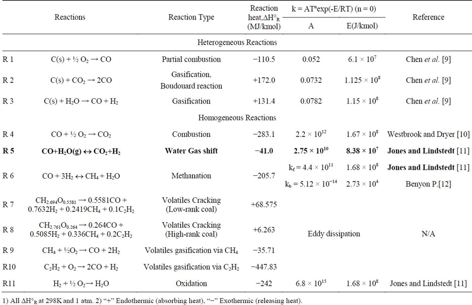
Table 1. Summary of reaction rate constants used in this study.
1) All DH°R at 298K and 1 atm. 2) “+” Endothermic (absorbing heat), “−” Exothermic (releasing heat).
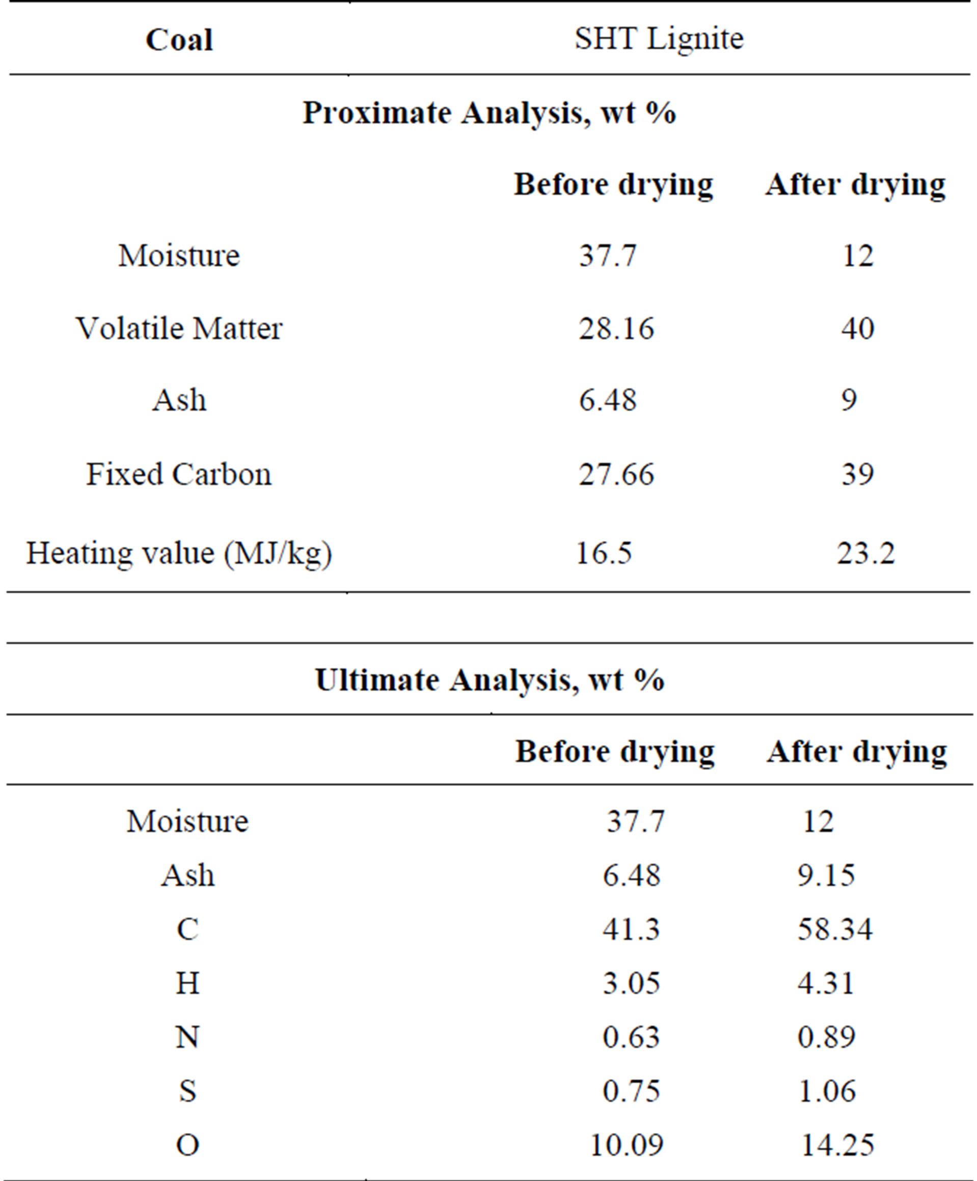
Table 2. The proximate and ultimate analyses of SHT Lignite.
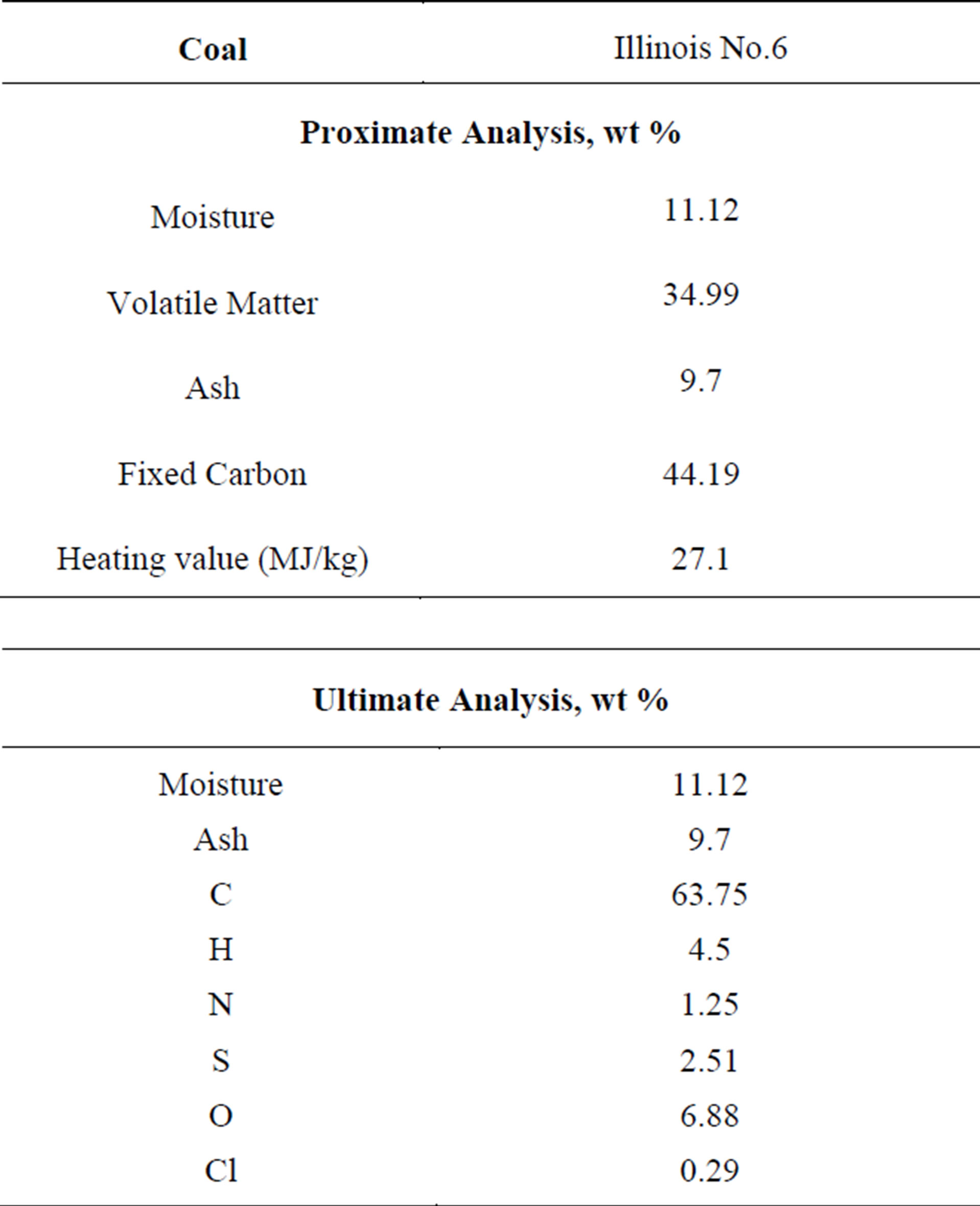
Table 3. The proximate and ultimate analyses of Illinois No.6 bituminous coal.
peated here, but they are briefly summarized below. The time-averaged steady-state Navier-Stokes equations as well as the mass and energy conservation equations are solved. Species transport equations are solved for all gas species involved. The standard k-ε turbulence model is used to provide closure. Silaen and Wang (2010) applied five turbulence models (standard k-ε, k-ω, RSM, k-ω SST, and k-ε RNG) and reported that the standard k-e turbulence model yields reasonable results without requiring very much computational time when compared to other turbulence models. Enhanced wall function and variable material property are used. The P1 model is used as the radiation model [13].
The flow (continuous phase) is solved in Eulerian form as a continuum while the particles (dispersed phase) are solved in Lagrangian form as a discrete phase. Stochastic tracking scheme is employed to model the effects of turbulence on the particles. The continuous phase and discrete phase are communicated through drag forces, lift forces, heat transfer, mass transfer, and species transfer. The finite-rate combustion model is used for the heterogeneous reactions, but both the finite-rate and eddy-dissipation models are used for the homogeneous reactions, and the smaller of the two is used as the reaction rate. The finite-rate model calculates the reaction rates based on the kinetics, while the eddy-dissipation model calculates based on the turbulent mixing rate of the flow. The Chemical Percolation Devolatilization (CPD) model [14-16] is chosen as the devolatilization model based on the finding by Silaen and Wang [13] that the Kobayashi two-competing rates devolatilization model [17] is very slow, while the CPD model gives a reasonable result.
For solid particles, the rate of depletion of the solid, due to a surface reaction, is expressed as a function of kinetic rate, solid species mass fraction on the surface, and particle surface area. The reaction rates are all global net rates, i.e., the backward reaction, calculated by equilibrium constants, are included in the global rate. Therefore, the finite rate employed in this study implicitly applies to the local equilibrium approach. Reaction rate constants used in this study are summarized in Table 1.
For liquid droplets, water evaporates from the particle’s surface when the temperature is higher than the saturation temperature (based on local water vapor concentration). The evaporation is controlled by the water vapor partial pressure until 100% relative humidity is achieved. When the boiling temperature (determined by the air-water mixture pressure) is reached, water continues to evaporate even though the relative humidity reaches 100%. After the moisture is evaporated, due to either high temperature or low moisture partial pressure, the vapor diffuses into the main flow and is transported away. Please refer to Silaen and Wang [9] for details.
3.1. Computational Models and Assumptions
The computational domain and elements on the gasifier wall are shown in Figure 1. The gasifier’s capacity is around 800 tons/day for coal input, producing syngas with an equivalent power of around 100 MW. The computational domain contains about 1.2 million elements. FLUENT 12.0.16 from ANSYS, Inc. is used as the CFD solver. The simulation is conducted under steady-state conditions. The segregated solver is selected, which decouples the momentum and energy equations. The SIMPLE algorithm is used to couple the pressure and velocity with an implicit pressure correction scheme. The second order upwind scheme is selected for spatial discretization of the convective terms and species. For the finite rate model, where the Eulerian-Lagrangian approach is used, the iterations are conducted by alternating between the continuous and the dispersed phases. Initially, two iterations in the continuous phase are conducted, followed by one iteration in the discrete phase to avoid the flame from dying out. Once the flame is stably established, five iterations are performed in the continuous phase followed by one iteration in the dispersed phase. The drag, particle surface reactions, and mass transfer between the dispersed and the continuous phases are calculated. Based on the calculation results in the dispersed phase, the continuous phase is updated in the next iteration, and the process is repeated. Converged results are obtained when the residuals satisfy a mass residual of 10−3, an energy residual of
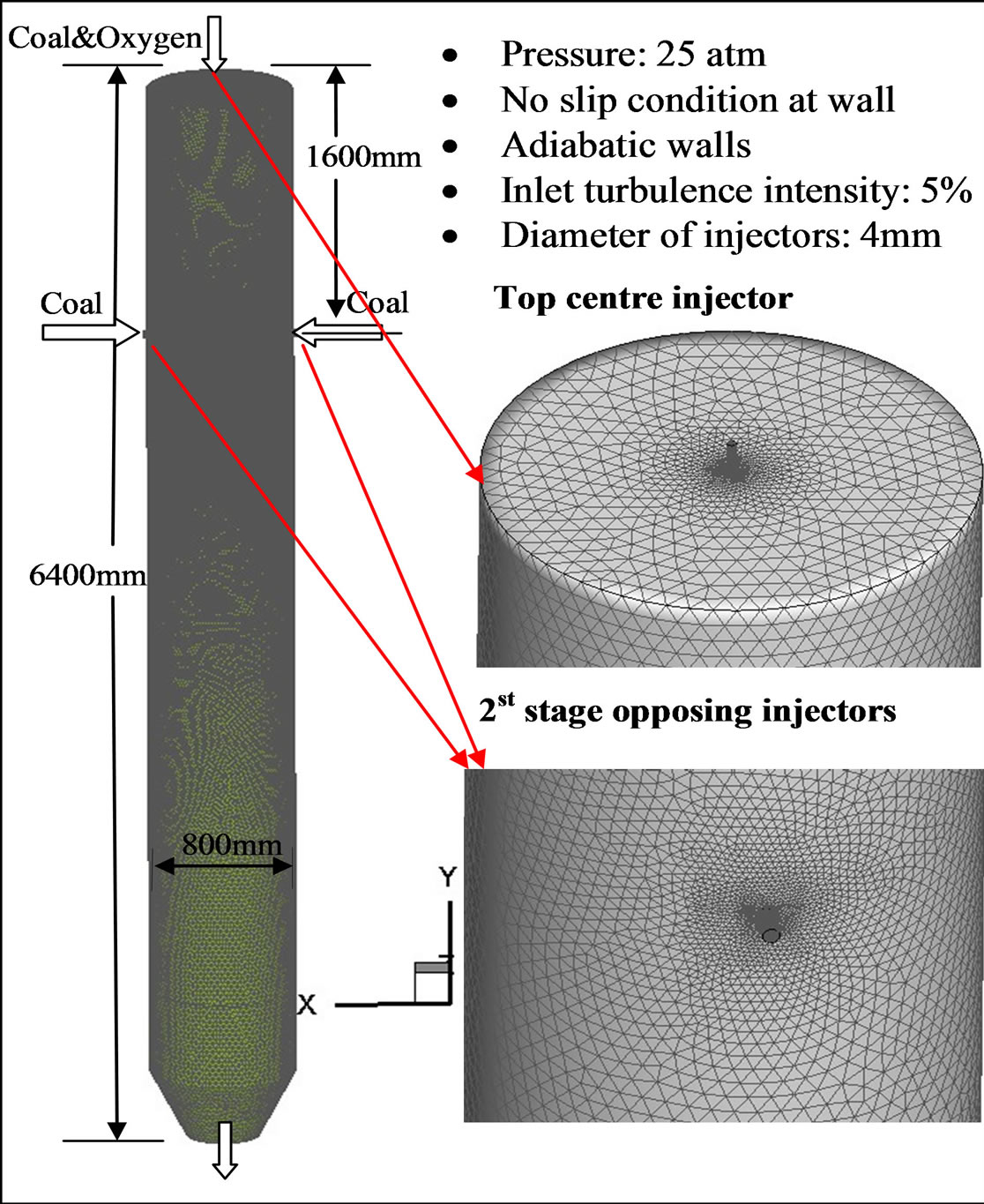
Figure 1. Meshed computational domain of the two-stage entrained-flow gasifier.
10−5, and momentum and turbulence kinetic energy residuals of 10−4. These residuals are the summation of the imbalance in each cell, scaled by a representative for the flow rate.
In the simulations, the buoyancy force is considered, varying fluid properties are calculated for each species and the gas mixture, and the walls are assumed impermeable and adiabatic. Since each species’s properties, such as density, Cp value, thermal conductivity, absorption coefficient, etc. are functions of temperature and pressure, their local values are calculated by using a piecewise polynomial approximation method. The mixture properties are calculated using a mass-weighted average method. The flow is steady, and the no-slip condition (zero velocity) is imposed on the wall surfaces.
3.2. Boundary and Inlet Conditions
The summary of the studied cases is listed in Table 4. In Case 1 (baseline case), SHT Lignite is used for a dry-fed, single-stage fuel feeding scheme. Based on a DOE/NETL report (2011), the lignite must be dried to 12 percent moisture before being injected into the gasifier. After the pre-drying process, the higher heating value (HHV) of the SHT Lignite is increased from 14.9 MJ/kg to 20.9 MJ/kg. It should be noted that the energy spent on pre-drying the lignite is about 659 kJ/kg. The mass flow rate of the dry coal is 2.625 kg/s and the mass flow rate of the oxidant is 1.7 kg/s. The oxidant/dry coal feed rate gives the O2/C stoichiometric ratio of 0.3. The stoichiometric ratio is defined as the percentage of oxidant provided over the stoichiometric amount required for the complete combustion of carbon. N2 (5% of the total weight of the oxidant) has been injected with O2 to transport the coal powder into the gasifier. The operating pressure is 25 atm.
In Case 2, a two-stage fuel feeding scheme is employed using SHT Lignite, with 25% - 75% coal distribution between the top (first) and the bottom (second) injection stages. The oxygen is injected entirely from the top injector. Case 3 is identical to Case 1 using single-stage fuel feeding scheme, except for the fact that Illinois No.6 bituminous coal is used. With the purpose of investigating the effects of the inherent moisture of the low-rank coals on the gasification process, Case 4 is conducted using single-stage gasification and SHT Lignite without predrying. By keeping the same amount of char and volatiles inside of the coal particles, the only difference in lignite’s composition with and without the pre-drying process is the amount of moisture. Case 5 is a single-stage coal feeding configuration using SHT Lignite with water injection at the second stage without preheating. The mass ratio between coal and total water including inherent moisture and slurry water is 60% to 40%. The inherent moisture is treated as a part of the coal, different from the water added to make the slurry. The slurry water is injected as droplets. Both the coal and water particle sizes are uniformly given as 50 µm for the purpose of conveniently tracking the change of particle sizes, even though it is understood that the actual particle size distribution is not uniform.
The walls are assigned as adiabatic with an internal surface emissivity of 0.8. The boundary condition of the discrete phase at the walls is assigned as “reflect,” which means that the discrete phase elastically rebounds off once reaching the wall. At the outlet, the discrete phase simply escapes/exits the computational domain. An area near the coal injection locations is initially patched with a temperature of 1500 K to simulate the ignition process of a real operation. The limit of the highest temperature is assigned to be 3500 K, and the limit of the lowest temperature is assigned to be 400 K. This will remove potential runaway conditions caused by erratic, unreasonably high, or low temperatures during the iteration process.
4. Results and Discussions
4.1. Comparison between Low-Rank Coal and High-Rank Coal (Case1 vs. Case 3)
Cases 1 and 3 use a single-stage, oxygen-blown, downdraft mode of operation with SHT Lignite and Illinois
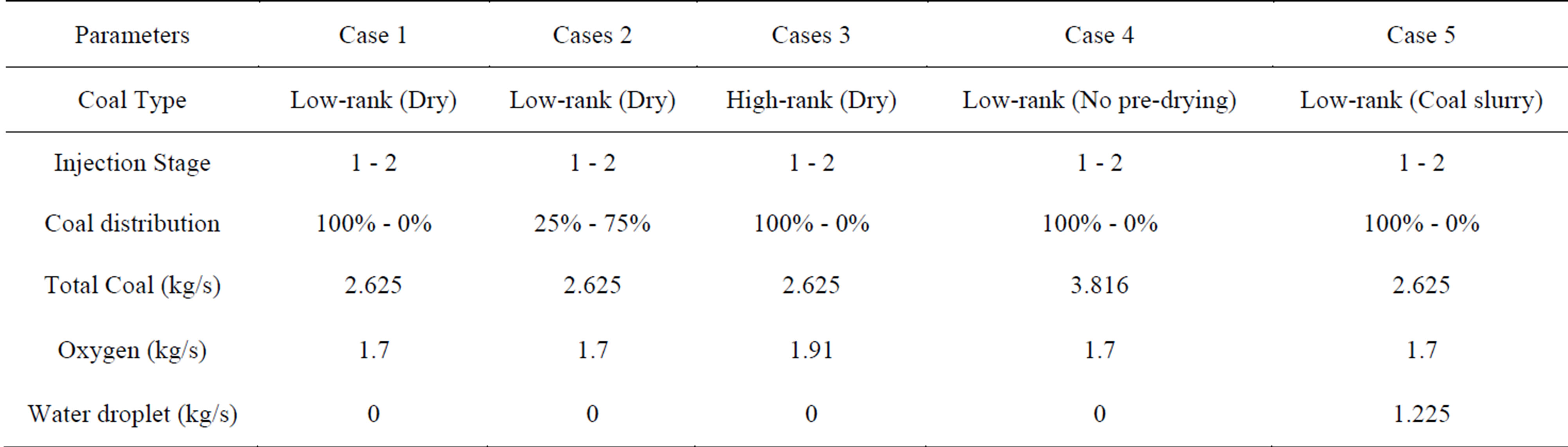
Table 4. Parameter and operating conditions of the studied cases.
No.6 bituminous coal, respectively. They both have the same dry coal mass flow rate, which is 2.625 kg/s, and the same O2/C stoichiometric ratio of 0.3, so the mass flow rate of injected oxygen is 1.7 kg/s in Case 1 and 1.91 kg/s in Case 3, respectively. Dry coal in this study means that no additional steam or water is added during fuel injection, although inherent moisture after pre-drying is still included in the coal.
The syngas temperature and species mole fraction distributions on the horizontal and selected vertical mid-planes in the gasifier for Case 1 are shown in Figure 2. Since all of the fuel and oxidant are injected from the top for the single-stage injection cases, the gas temperature is higher in the top injection region than it is at the second stage location. The maximum gas temperature in the top injection stage is 2300K. The dominant reaction in the top injection stage consists mainly of the intense char combustion (C + ½ O2 → CO and CO + ½ O2 → CO2) in the first stage and gasification reactions (mainly C + ½ CO2 → CO, C + H2O → CO + H2) in the second stage. Due to the exothermic nature of the combustion process and the endothermic nature of the gasification reactions, the temperature drops gradually from the top injection to the exit of the gasifier. Oxygen is completely depleted through the char combustion in the top injection region. CO2 can be seen quickly produced near the top in Figure 2, but it is consumed by the gasification process C + ½ CO2 → CO in the rest of the gasifier.
Table 5 shows the temperature and syngas compositions at the exit for Cases 1 and 3. It can be observed that the syngas temperature at the exit from low-rank coal gasification (Case 1) is 538 K (21%) lower than it is for high-rank coal gasification (Case 3). In the meantime, the syngas HHV of Case 1 is 18% (30,222 kJ/kmol) greater than that of Case 3 due to the higher volume fraction of CO and H2. It should be noted that the HHV in this study is calculated at 25˚C, including the sensible and latent heat of the water vapor in the syngas’s composition as part of the fuel—this is not the same sensible or latent heat to be released from the water vapor in the product after syngas is burned.
It is shown in Tables 2 and 3 that the volatile content (40%) is higher than the fixed carbon (39%) after the pre-drying process of the SHT Lignite. On the contrary, for the high-rank coal, the fixed carbon content is 26% higher than that of the volatiles (44.19% vs. 34.99%). Therefore, keeping the same fuel mass flow rates, more oxygen needs to be injected in order for the high-rank coal to go through the partial combustion process with the same O/C stoichiometric ratio. The gasification process is more productive in the SHT Lignite gasification process since more volatiles could go though the volatile cracking-gasification process (R7 - R10) to produce more syngas with a relatively lower exit temperature. Based on this result, low-rank coals could be a very competitive fuel for coal gasification.
4.2. Comparison between Single-Stage and Two-Stage Fuel Feeding Schemes (Case 1 vs. Case 2)
Among the existing commercial coal gasifiers, the twostage fuel feeding scheme has been employed only in updraft gasifiers, such as the E-GAS gasifier and the Mitsubishi Heavy Industries gasifier. In this study, the
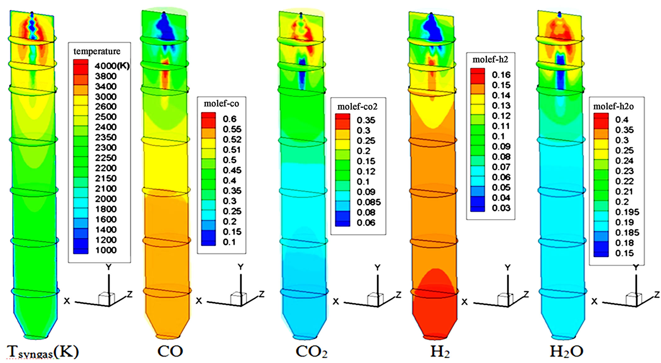
Figure 2. Syngas temperature and species mole fraction distributions of Case 1.
two-stage fuel feeding scheme is investigated in a downdraft, entrained-flow, refractory-lined reactor. The twostage coal feeding gasification process injects all of the oxygen in the first stage and provides a certain amount of coal without oxygen in the second stage. The endothermic gasification processes downstream of the second stage could keep the gasifier at a lower temperature. Hence, the life of the refractory bricks can be extended, and the associated maintenance costs can be reduced. However, this benefit gained at the second stage is obtained at the cost of a higher peak combustion temperature in the first stage compared to a typical one-stage gasifier. Since the combustion temperature of low-rank coal is lower than that of high rank coal, it is hypothesized that low-rank coals can help reduce the peak temperature in the first stage. Therefore, hypothetically, itseems that it is more advantageous to utilize low-rank coals in a two-stage coal gasification process. In this study, two-stage fuel feeding is simulated in Case 2 using SHT Lignite with a 25% - 75% coal distribution between the top and the second injection stages. The oxygen is injected entirely through the top injector, i.e. no oxygen is injected at the second stage. The total mass flow rates of coal and oxygen are the same as those in Case 1.
Figure 3 shows the syngas temperature distribution of Case 2. It can be observed clearly that combustion reactions dominate throughout the first stage, with a peak syngas temperature of approximately 3500 K. Since 75% of the coal is injected at the second stage, active gasification reactions take place and dominate from the second stage onwards. The syngas temperature decreases gradually from near the first injection location to 1850 K at the exit. Table 6 compares the syngas temperature, composition, and HHV at the exit between Cases 1 and 2. Compared to the single-stage injection scheme (Case 1), the two-stage fuel feeding scheme (Case 2) effectively reduces the syngas temperature by 15 % (320K) and increases the syngas HHV by 1% (1468 kJ/kmol). Furthermore, Figures 4 and 5 show that, compared to the single-stage scheme, the two-stage fuel feeding scheme also reduces the wall temperature by about 100 K at the lower 60% of the gasifier, but it results in higher peak wall temperature (about 100 K) near the second stage. Figure 5 shows that the peak syngas temperatures appear at the first stage in both cases due to the strong presence of coal combustion reactions. The syngas temperature drops more sharply in Case 2 because of the strong endothermic gasification reactions between the syngas and
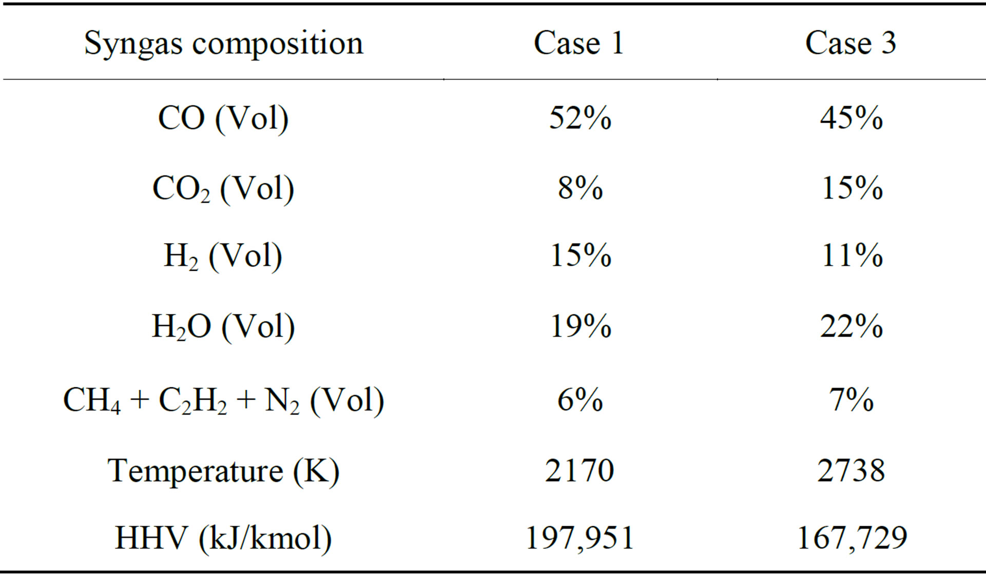
Table 5. Comparison of the results of syngas temperature, composition, HHV at exit between Case 1 (Lignite) and Case 3 (Illinois #6) (The sensible heat of water vapor in the syngas is counted for HHV).
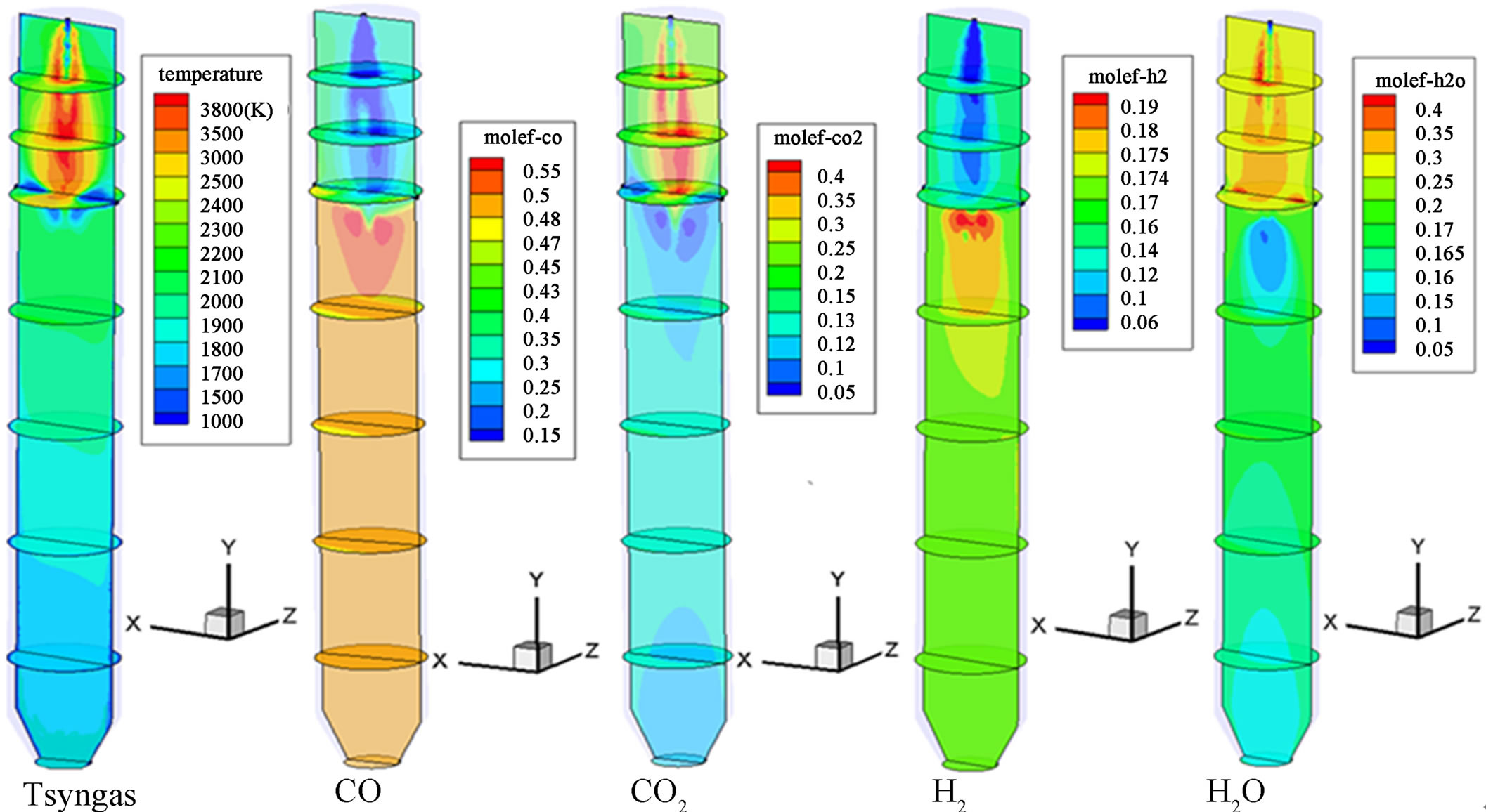
Figure 3. Synas temperature and species mole fraction distributions of Case 2.
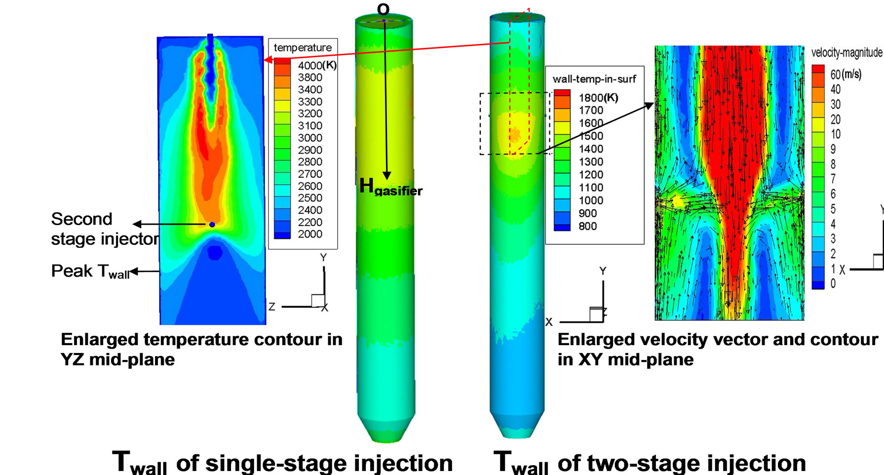
Figure 4. Contours of inner wall temperature distributions of Cases 1 and 2.
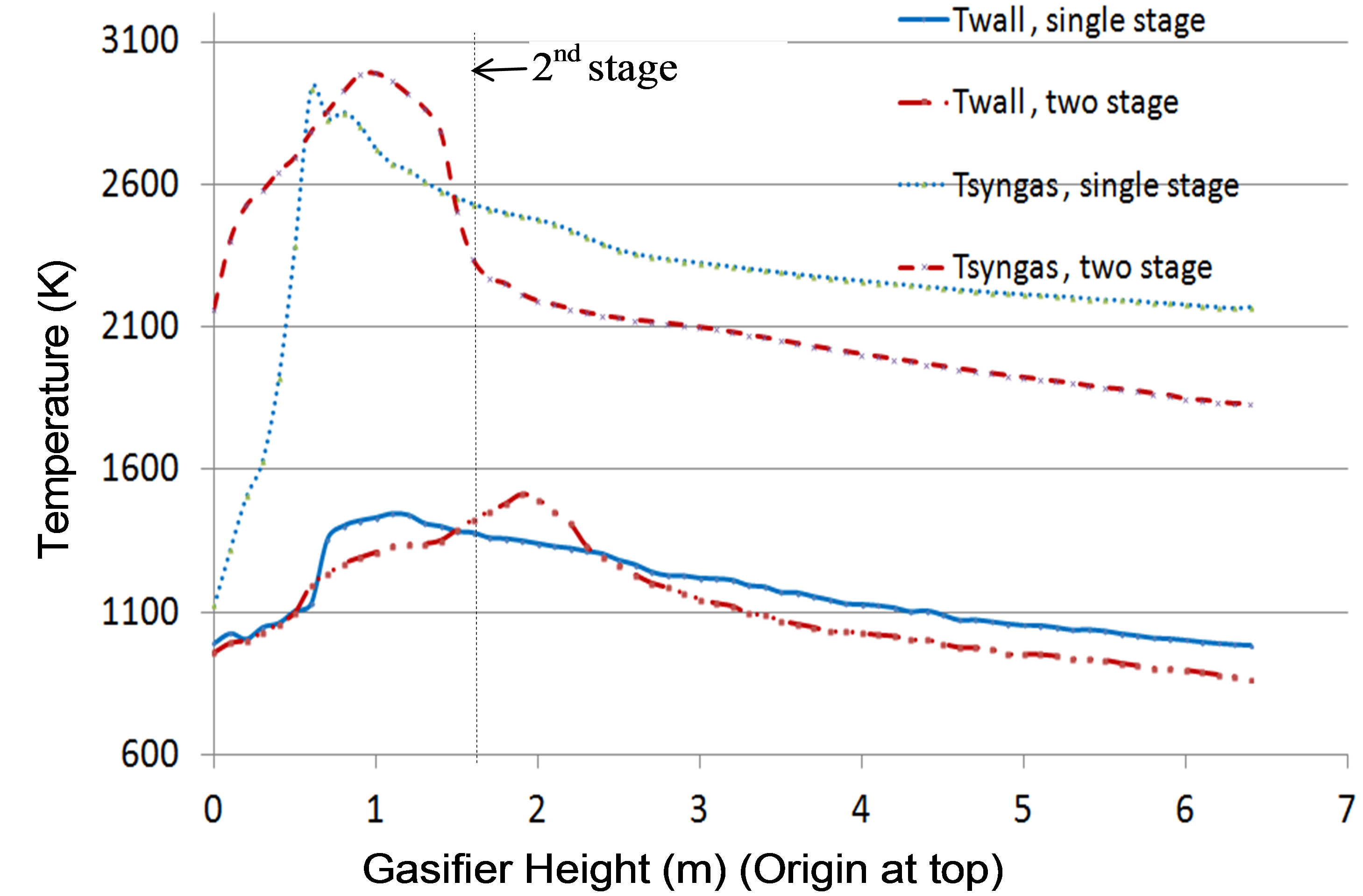
Figure 5. Circumferentially averaged inner wall temperature distribution along the gasifier of Case 1 and Case 2.
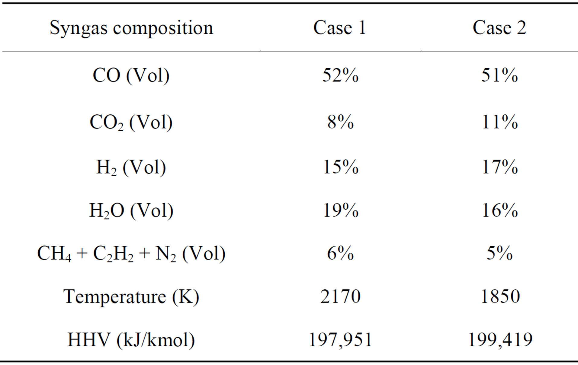
Table 6. Comparison of the results of syngas temperature, composition, HHV at exit between Case 1 and Case 2.
coal particles at the second injection stage. It is interesting to discover that the peak wall temperature does not appear at the first stage, but appears at the location which is about 0.3 meters lower than the second injection location. In order to find the reason, a contour plot of the syngas velocity field in the XY mid-plane cutting through the injection holes and a contour plot of the syngas temperature in the YZ mid-plane (perpendicular to the second injection direction) are shown in Figure 4. It is clearly shown here that the opposing jets in the XYmid-plane issued at the second injection location squeeze the mainstream of hot syngas from the center to the side of gasifier, touching the wall in the YZ-mid-plane. Consequently, the inner wall is heated in the region intercepting this compressed hot plane, resulting in the peak wall temperature located a little bit lower than the second injection location (since the main stream is going downwards).
4.3. Comparison of Lignite Gasification Performance with and without Pre-Drying Process (Case 1 vs. Case 4)
As explained in the introduction, considering the fact that the high moisture content of low-rank coals leads to high transportation costs and the low thermal efficiency of the gasification process, most of moisture needs be removed before the low-rank coal is either injected into a dry-fed gasifier or mixed with water and injected as slurry. In this study, SHT Lignite is dried to 12 percent of moisture. Table 2 shows the lignite’s proximate analysis, ultimate analysis, and HHV before and after the pre-drying process. After the pre-drying process, the lignite’s HHV increases by 41%. It should be noted that the energy spent on predrying the lignite is about 659 kJ/kg, which is calculated as 2258 kJ/kg (latent heat at 1bar) × 0.292 (amount of vaporized water per 1kg coal). Since it is more difficult to vaporize the abundant inherent moisture in low-rank coals, more energy and residence time will be required for the “demoisturization” process. It is interesting to investigate how the “demoisturization” process would affect the effectiveness of the gasification process without first predrying the coal.
In order to include the resistance of driving the inherent moisture out of the pores of low-rank coals, a simple model is applied by increasing the standard latent heat of water by 20%. This case, without pre-drying, is assigned to be Case 4. Table 7 compares the results of syngas temperature, composition, and HHV for Cases 4 and 1. Without pre-drying (Case 4), the syngas HHV decreases by 27%, both the H2 and CO concentrations decrease by 33% (vol), and the water vapor concentration increases by 121% (vol). This is not a surprising result because the delivered lignite, before pre-drying, only contains 78% of the HHV present after pre-drying, and a significant amount of the high-grade combustion energy is used to vaporize the large amount of inherent moisture in the fuel. Figure 6 shows the contour plots of syngas temperature and species mole fraction distributions of Case 4. In comparison with Case 1 in Figure 2, the influence of the large amount of inherent moisture can be seen from following three observations:
1) The high H2O mole fraction values exist in a larger region in Case 4 (Figure 6) compared to in Case 1.
2) The presence of this high H2O mole fraction does not effectively react with C to produce H2 via the steamgasification process (C + H2O ® H2 + CO), perhaps due to the fact that the water vapor is newly formed via demoisturization, and it will take time to react with char. This minimal steam-gasification process leads to low H2 and CO mole fractions near the upper 20% of the gasifier.
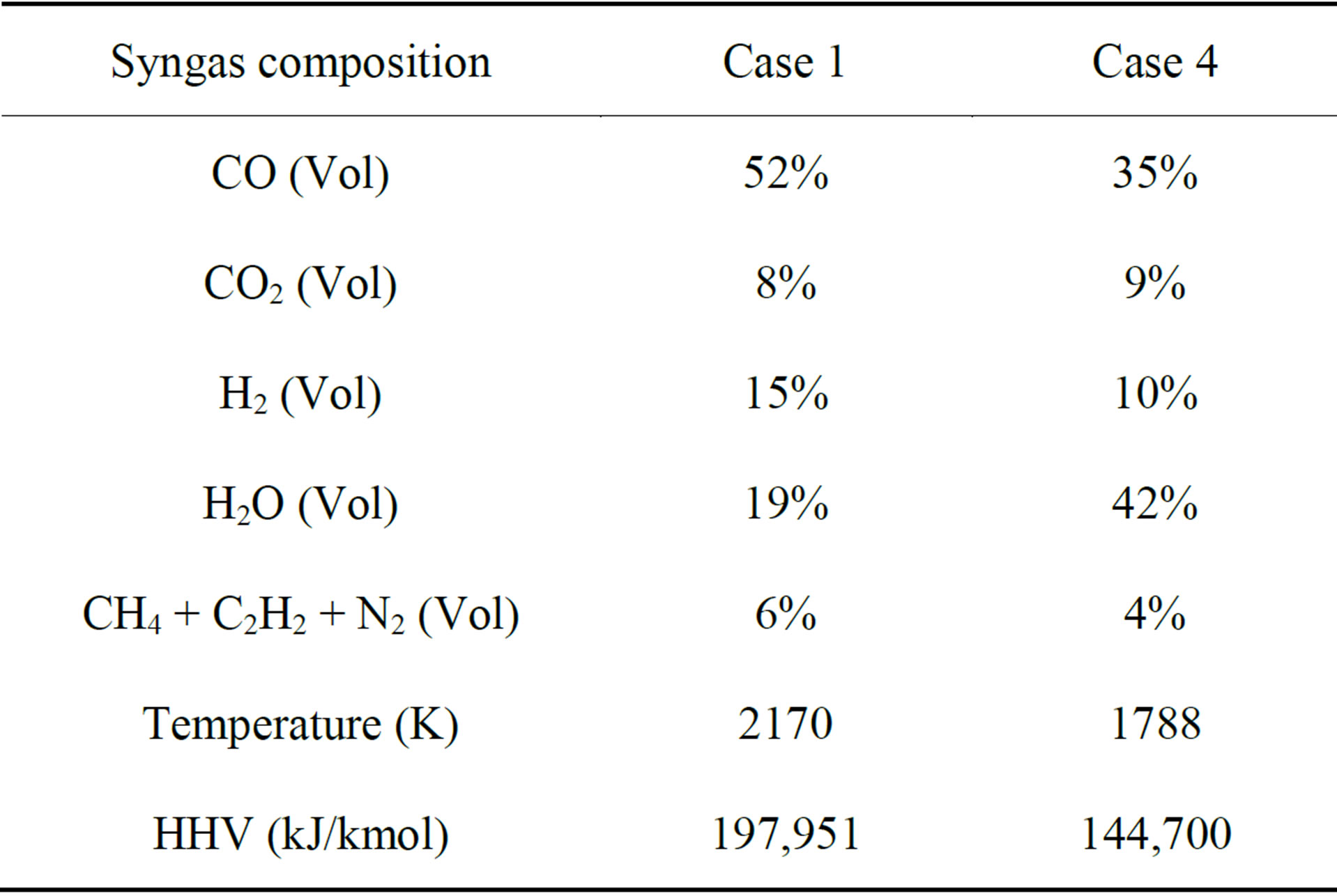
Table 7. Comparison of the results of syngas temperature, composition, HHV at exit between Case 1 and Case 4.
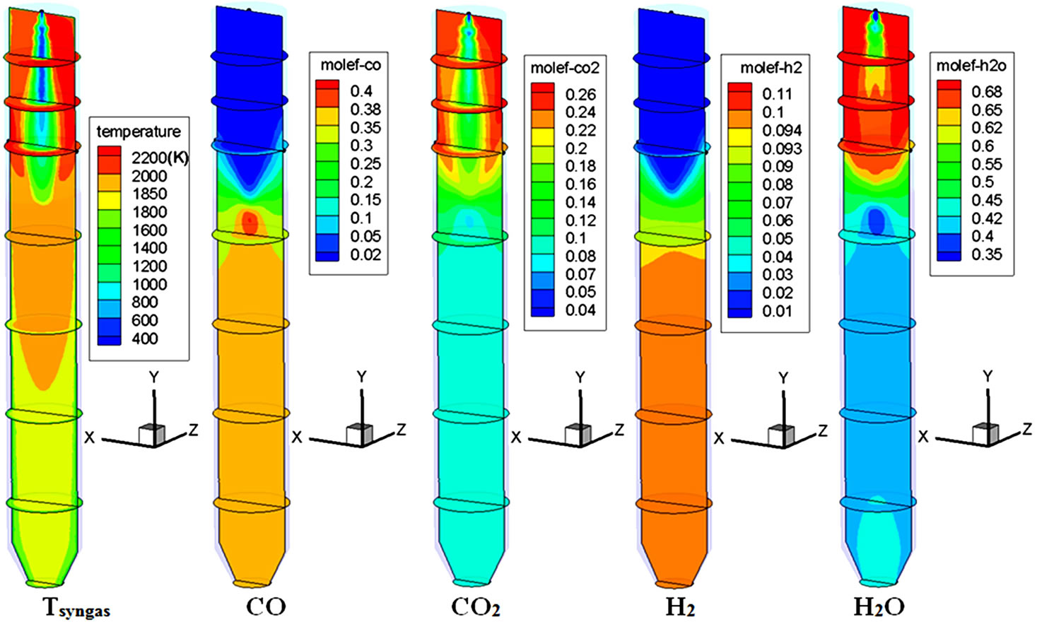
Figure 6. Syngas temperature and species mole fraction distributions of Case 4 (no pre-drying).
3) The temperature near the top injector region in Case 4 is about 1500 K cooler than it is in Case 1.
To further understand the physics, the reaction rates of the three heterogeneous reactions: the combustion reaction, water-gas shift reaction, and thermal cracking reaction are calculated and compared between Case 1 and Case 4 as shown in Figure 7. It is clearly shown that all of the reactions actively take place in the region near the top fuel injection area in Case 1, while, in Case 4, all of the reactions are delayed until after the first third of the gasifier’s height. With the exceptions of reactions 3 and 5, which involve H2O, during the peak reactions, all of the reactions in Case 1 have much higher reaction rates (5 - 10 times) than those in Case 4. These phenomena illustrate the influence that the large inherent moisture content has on delaying the gasification process. Therefore, it is beneficial to pre-dry low-rank coals to below 12% total moisture content before injecting them into the gasifier.
4.4. Comparison of Dry Coal Gasification with Coal Slurry Gasification Using SHT Lignite (Case 1 vs. Case 5)
For a slurry-fed gasifier, coal is mixed with a certain amount of water before it is injected into the gasifier. It should be noted that the water used for mixing with the coal is treated as surface moisture, which is different from the inherent moisture embedded in the coal structure. In order to more accurately simulate the coal slurry gasification process by differentiating between these two different types of moisture, the surface moisture is modeled by injecting water with standard latent heat, while the inherent moisture is modeled inside of the coal as a part of its composition. The demoisturization process of the inherent moisture is modeled by adding more energy to drive the moisture out through the lattice or pores inside the coal structures. This additional energy is accounted for by increasing the standard latent heat of water by 20%.
Case 5 is a single-stage, slurry-fed configuration using pre-dried SHT Lignite with a total-water-to-dry-coal mass flow ratio of 40% - 60%. The total water includes the 12% inherent moisture and 28% added water (surface moisture). The added water is injected alongside the coal as 50 mm water droplets from the top of gasifier. Table 8 shows the comparison of syngas composition, temperature, and HHV at the exit between Cases 1 and 5. When the coal slurry is injected into the gasifier in Case 5, the exit syngas temperature decreases by 15% (323 K) com-

Figure 7. Reaction rates of Case 1 and 4.
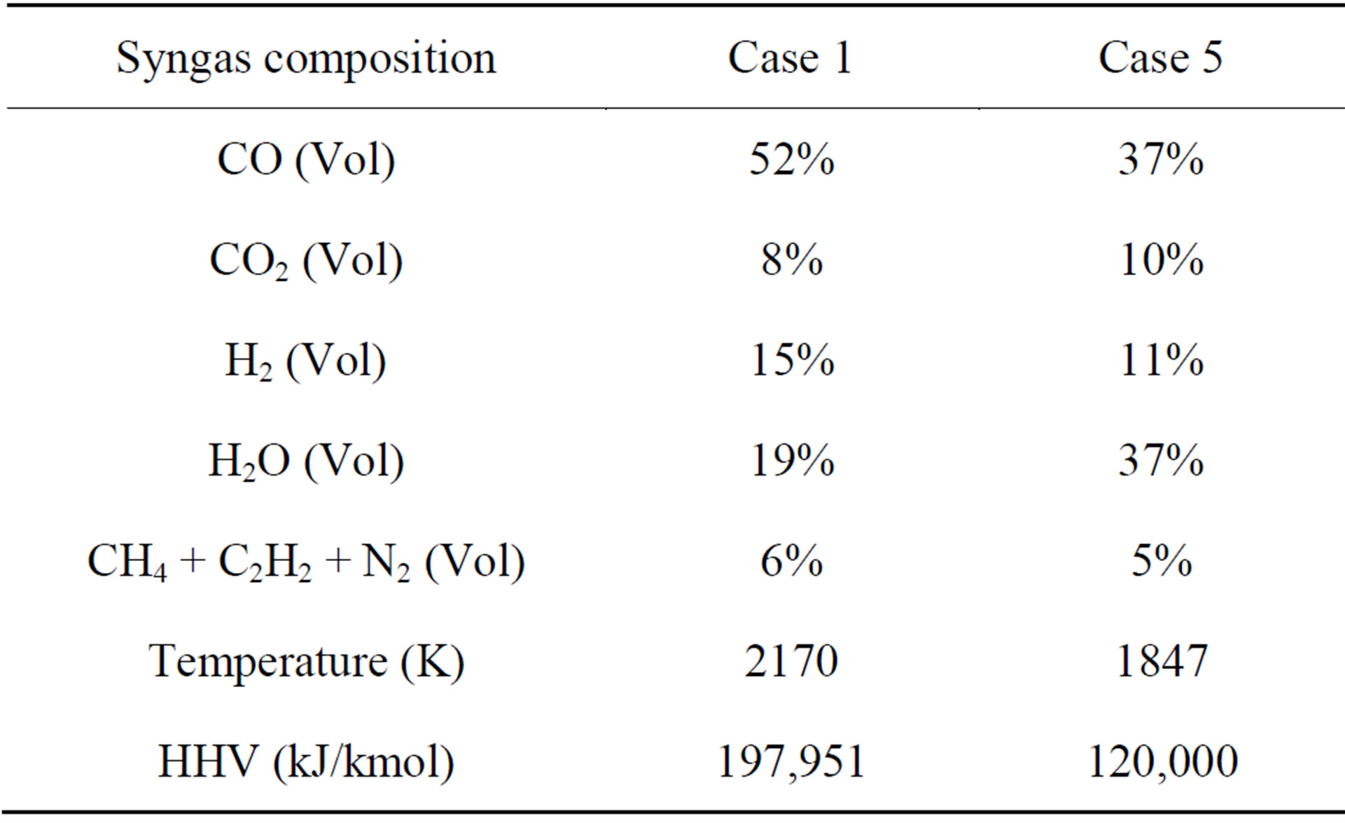
Table 8. Comparison of syngas temperature, composition, and HHV at the exit between Cases 1 and 5.
pared to Case 1. The syngas HHV in Case 5 decreases by 39% (77,951 kJ/kmol) as well, since H2O now occupies 37% (volume fraction) of the total gas mixture at the exit, which is 1.9 times that of the syngas result for Case 1. Based on this result, a conclusion can be drawn that the syngas temperature and HHV will decrease significantly when a coal slurry is used as the feedstock. The syngas HHV includes the latent heat of water vapor in the fuel as well as in the product.
5. Conclusions
This paper focuses on a low-rank coal gasification study. SHT Lignite was used as the low-rank coal and Illinois No.6 bituminous coal was used as the high-rank coal in this study. Several comparisons have been conducted on the same operating conditions: 1) low-rank coal vs. highrank coal; 2) one-stage injection vs. two-stage injection; 3) low-rank coal with pre-drying vs. without pre-drying; and 4) dry coal feeding without steam injection vs. with steam injection at the second stage. Several conclusions are drawn as follows:
1) Syngas produced from lignite has 21% (538 K) lower exit temperature and 18% (30,222 kJ/kmol) greater HHV than syngas produced from Illinois #6 (high-rank coal). Based only on this result of HHV value, it follows that low-rank coal could be a better alternative fuel for coal gasification.
2) The one-stage and two-stage fuel injection schemes have similar syngas compositions and Higher Heating Values at the exit. However, the two-stage fuel feeding scheme results in a lower wall temperature (around 100 K) in the lower half of the gasifier than the single-stage injection scheme. The introduction of the second injection with a pair of opposing jets produces a flattened plane stretching from the hot reaction zone laterally towards the wall, resulting in a peak wall temperature about 0.3 meters downstream of the second injection location.
3) Without pre-drying, the high inherent moisture content in the lignite causes the syngas HHV to decrease by 27% and the mole fractions of both H2 and CO to decrease by 33%, while the water vapor content increases by 121% (by volume). The low-rank coal, without predrying, will take longer to finish the demoisturization and devolatilization processes, resulting in delayed combustion and gasification processes.
4) When the coal slurry, made with pre-dried lignite with the mass of total water (inherent moisture + surface moisture) to dry coal of 40% - 60%, is injected into the gasifier, the exit syngas temperature decreases by 15% (323 K) and the syngas HHV decreases by 39% (77,951 kJ/kmol) compared with dried feed in Case 1.
Acknowledgment
This study was partially supported by the U.S. Department of Energy via a subcontract through Nicholls State University.
REFERENCES
- BP. Statistical Review of World Energy, 2005.
- J. L. Johnson, “Kinetics of Coal Gasification: A Compilation of Research,” John Wiley and Sons, New York, 1979, p. 324.
- A. Linares-Solano, O. P. Mahajan, L. Philip and P. L. Walker, “Reactivity of Heat-treated Coals in Steam,” Fuel, Vol. 58, No. 5, 1979, pp. 327-332. http://dx.doi.org/10.1016/0016-2361(79)90148-0
- L. Philip, P. L. Walker, S. Matsumoto, T. Hanzawa, T. Muira and I. M. K. Ismail, “Catalysis of Gasification of Coal-Derived Cokes and Chars,” Fuel, Vol. 62, No. 2, 1983, pp. 140-149. http://dx.doi.org/10.1016/0016-2361(83)90186-2
- M. Karthikeyan, Z. H. Wu and A. S. Mujumdar, “LowRank Coal Dry Technologies-Current Status and New Developments,” Dry Technology, Vol. 27, No. 3, 2009, pp. 403-415. http://dx.doi.org/10.1080/07373930802683005
- US Department of Energy/NETL, “Cost and Performance Baseline for Fossil Energy Plants Volume 3a: Low Rank Coal to Electricity: IGCC Cases,” 2011.
- D. L. Smoot and P. J. Smith, “Coal Combustion and Gasification,” Plenum Press, New York, 1985. http://dx.doi.org/10.1007/978-1-4757-9721-3
- X. Lu and T. Wang, “Water-Gas Shift Modeling in Coal Gasification in an Entrained-Flow Gasifier, Part 1: Development of Methodology and Model Calibration,” Fuel, Vol. 108, 2013, pp. 629-638.
- C. Chen, M. Horio and T. Kojima, “Numerical Simulation of Entrained Flow Coal Gasifiers,” Chemical Engineering Science, Vol. 55, No. 18, 2000, pp. 3861-3833. http://dx.doi.org/10.1016/S0009-2509(00)00030-0
- C. K. Westbrook and F. L. Dryer, “Simplified Reaction Mechanisms for the Oxidation of Hydrocarbon Fuels in Flames,” Combustion Science and Technology, Vol. 27, 1981, pp. 31-43.
- W. P. Jones and R. P. Lindstedt, “Global Reaction Schemes for Hydrocarbon Combustion,” Combustion and Flame, Vol. 73, No. 3, 1998, p. 233. http://dx.doi.org/10.1016/0010-2180(88)90021-1
- P. Benyon, “Computational Modelling of Entrained Flow Slagging Gasifiers,” Ph.D. Thesis, School of Aerospace, Mechanical & Mechatronic Engineering, University of Sydney, Australia, 2002.
- A. Silaen and T. Wang, “Effect of Turbulence and Devolatilization Models on Gasification Simulation,” International Journal of Heat and Mass Transfer, Vo. 53, 2010, pp. 2074-2091.
- T. H. Fletcher, A. R. Kerstein, R. J. Pugmire and D. M. Grant, “Chemical Percolation Model for Devolatilization: 2. Temperature and Heating Rate Effects on Product Yields,” Energy and Fuels, Vol. 4, No. 1, 1990, pp. 54-60. http://dx.doi.org/10.1021/ef00019a010
- T. H. Fletcher and A. R. Kerstein, “Chemical Percolation Model for Devolatilization: 3. Direct Use of 13C NMR Date to Predict Effects of Coal Type,” Energy and Fuels, Vol. 6, No. 4, 1992, pp. 414-431. http://dx.doi.org/10.1021/ef00034a011
- D. M. Grant, R. J. Pugmire, T. H. Fletcher and A. R. Kerstein, “Chemical Percolation of Coal Devolatilization Using Percolation Lattice Statistics,” Energy and Fuels, Vol. 3, No. 2, 1989, pp. 175-186. http://dx.doi.org/10.1021/ef00014a011
- H. Kobayashi, J. B. Howard and A. F. Sarofim, “Coal Devolatilization at High Temperatures,” 16th Symposium (International) on Combustion, 1976, pp. 411-425.