International Journal of Clean Coal and Energy
Vol.1 No.2(2012), Article ID:19454,14 pages DOI:10.4236/ijcce.2012.12002
The SECARB Anthropogenic Test: A US Integrated CO2 Capture, Transportation and Storage Test*
1Advanced Resources International, Inc., Arlington, USA
2Advanced Resources International, Inc., Knoxville, USA
3Electric Power Research Institute, Palo Alto, USA
4Southern States Energy Board, Norcross, USA
5Research & Environmental Affairs, Southern Company, Birmingham, USA
Email: {gkoperna, driestenberg, vkuuskraa}@adv-res.com, {rrhudy, rtrautz}@epri.com, hill@sseb.org, raesposi@southernco.com
Received January 28, 2012; revised March 5, 2012; accepted March 25, 2012
Keywords: CO2; Storage; Permitting; Capture; Characterization
ABSTRACT
The United States Department of Energy (DOE) seeks to validate the feasibility of injecting, storing and monitoring CO2 in the subsurface (geologic storage) as an approach to mitigate atmospheric emissions of CO2. In an effort to promote the development of a framework and the infrastructure necessary for the validation and deployment of carbon sequestration technologies, DOE established seven Regional Carbon Sequestration Partnerships (RCSPs). The Southeast Regional Carbon Sequestration Partnership (SECARB), whose lead organization is the Southern States Energy Board (SSEB), represents 13 States within the southeastern United States of America (USA). The SECARB Anthropogenic Test R&D project is a demonstration of the deployment of CO2 capture, transport, geologic storage and monitoring technology. This project is an integral component of a plan by Southern Company, and its subsidiary, Alabama Power, to demonstrate integrated CO2 capture, transport and storage technology. The capture component of the test takes place at the James M. Barry Electric Generating Plant (Plant Barry) in Bucks, Alabama. The capture facility, equivalent to 25 MW, will utilize post-combustion amine capture technology licensed from Mitsubishi Heavy Industries America. CO2 captured at the plant will be transported by pipeline for underground storage in a deep, saline geologic formation within the Citronelle Dome located in Citronelle, Alabama. At the end of the first quarter of 2012, up to 550 tonnes of CO2 per day will be captured and transported twelve miles by pipeline to the storage site for injection and subsurface storage. The injection target is the lower Cretaceous Paluxy Formation which occurs at 9400 feet. Transportation and injection operations will continue for one to two years. Subsurface monitoring will be deployed through 2017 to track plume movement and monitor for leakage. This project will be one of the first and the largest fully-integrated commercial prototype coal-fired carbon capture and storage projects in the USA. This paper will discuss the results to date, including permitting efforts, baseline geologic analysis and detailed reservoir modeling of the storage site, framing the discussion in terms of the overall goals of the project.
1. Introduction
Commercial-scale carbon capture and storage (CCS) technology deployment for the electrical utility industry will require a robust international research and development program with governmental support both in cost-share and in risk management. In an effort to comply with environmental legislation or regulation related to CO2, the electrical utility industry hope to be in a position to make financial decisions on utility boiler sourced CCS technology and associated risk management by 2020.
The United States Department of Energy (DOE) seeks to validate the feasibility of injecting, storing and monitoring CO2 in the Earth’s subsurface (geologic sequestration) in the near-term as an approach to mitigate atmospheric emissions of CO2. In an effort to “promote the development of a framework and the infrastructure necessary for the validation and deployment of carbon sequestration technologies,” DOE established seven regional carbon sequestration partnerships (RCSPs), representing 40 States, 3 Indian Nations, 4 Canadian Provinces and over 150 organizations. The Southeast Regional Carbon Sequestration Partnership (SECARB), whose lead organization is the Southern States Energy Board (SSEB), represents 13 States within the south eastern United States of America (USA), and includes the core operating area of Southern Company (Alabama, Georgia, Mississippi, and the Florida Panhandle; Figure 1).
In the southeastern USA, Southern Company, in partnership with the SSEB, the Electric Power Research Institute (EPRI), and Advanced Resources International (ARI), is participating in the DOE-RCSP Program, representing the SECARB. In this program, a 3000 tonne pilot injection into a saline reservoir was performed in 2008 at Mississippi Power Company’s Plant Daniel generation facility, located in southeast Mississippi. This demonstration enabled the project team to gain valuable experience with site characterization, permitting, outreach & education, and the injection and monitoring of CO2 into a deep, saline reservoir [1].
Previous SECARB Phase II pilot-scale field tests in Mississippi [2-5], Alabama [6], and Virginia [7] (in conjunction with numerous other sequestration field tests around the USA [8]) have demonstrated the ability to safely inject and monitor CO2 in coal seams, saline reservoirs, and depleted oilfields. The SECARB Phase III projects are now underway and consist of two parts; the Early Test (completed) is a large volume injection test utilizing natural CO2 (associated with an enhanced-oilrecovery flood) located at the Cranfield oilfield in Mississippi [9]. The focus of this paper is the second part of this Phase III project; a demonstration of integrated deployment of CO2 capture, transport, and geologic storage technology for an existing pulverized coal-fired power plant.
The large-scale capture, transportation and injection experiment, called the “Anthropogenic Test” is an integral component of a plan by Atlanta-based Southern Company, and its subsidiary, Birmingham-based Alabama Power, to demonstrate CO2 capture and storage technology at the James M. Barry Electric Generating Plant (Plant Barry) in Bucks, Alabama utilizing capture technology licensed from Mitsubishi Heavy Industries America [10]. CO2 emissions captured at the plant will be transported by pipeline for underground storage in a deep, saline geologic formation within the Citronelle Field, an oilfield that lies on the crest of the Citronelle Dome, located in Mobile County, Alabama (Figure 1).
Southern Company and Mitsubishi Heavy Industries have funded and constructed a CO2 capture facility at Alabama Power’s 2657-megawatt Plant Barry. Beginning in 2011, up to 550 tonnes of CO2 per day, the equivalent emissions from 25 MW of the plant’s power electric generating have been captured at the facility. Transportation and injection operations will begin in 2012 continue for up to two years, with subsurface monitoring deployed through 2017. This project will be
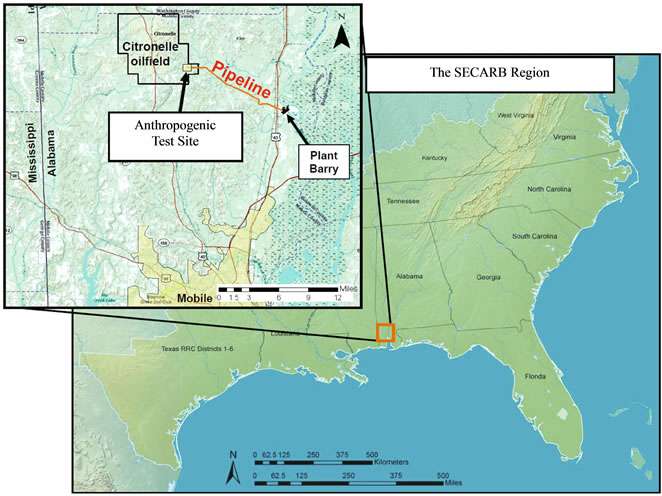
Figure 1. SECARB Partnership States. The inset map locates Plant Barry and the injection site.
one of the first and the largest fully-integrated pulverized coal-fired CCS projects in the USA.
2. Project Design
Capture Technology. The technology deployed for capturing CO2 from the power plant is the Mitsubishi Heavy Industries (MHI) KM-CDR process, which utilizes the proprietary KS-1 solvent to achieve high levels of CO2 retention with significant reductions in energy penalty from current technologies [10]. The CO2 capture and compression island will be a fully integrated and continuously operating unit, utilizing representative equipment and demonstrating MHI’s approach for process scale-up, an optimized flow sheet (flow-chart demonstrating the capture unit’s process), and improved unit operations within the base flow sheet. With an aggressive parametric test campaign, the project team expects to fully evaluate how the KM-CDR process will perform in utility service and collect the necessary data to develop a comprehensive process integration plan in preparation for the next phase of technology development. The process has been demonstrated at a smaller scale at a coal-fired generating station in Japan [11], and is currently being deployed commercially on natural gas-fired systems around the world [12]. This project represents the largest coalfired demonstration of this technology in the USA with the plant designed to capture up to 550 tonnes per day [13].
Engineering and Procurement were completed in July 2010 and the first shipment of components to the Plant site occurred in September 2010. The capture unit reached full operational capacity in June 2011 and is currently operating at full capacity. To date, the unit has already captured over 40,000 tonnes of CO2. Note that the coal-fired unit’s boiler was placed on reserve shutdown related due to mild weather from September to October. In late October the unit was shut down for a planned maintenance outage. The capture facility is scheduled to return on line during the first quarter of 2012.
Pipeline Transport. A 4-inch pipeline was constructed that stretches approximately 12 miles (19 kilometers) from the outlet of the CO2 capture facility to the point of injection at the injection wellsite within Citronelle Field. The fit-for-purpose pipeline was constructed of standard API 5L X-65 grade pipe with wall thickness between 0.48 and 0.56 centimeters. The route has a 40 foot (12 meter) right of way permanent easement that parallels an existing electric transmission line that crosses nine landowners who possess significant tract acreages. Some of the larger tract owners include Alabama Power Company, a timber company, a bank managed land trust, and a property which is owned fee simple by Denbury Onshore. The injection wells and surface facilities are located on Denbury’s fee simple acreage.
The main route encountered an undulating terrain with upland timber, stream crossings, and a variety of wetland types that were avoided or mitigated if openly crossed to minimize environmental impact. One notable aspect of the pipeline construction effort was the abundance of Gopher Tortoise (Gopherus Polyphemus) burrows encountered along the right of way. The Gopher Tortoise is listed by the U.S. Fish and Wildlife service as a “Threatened Species” in the region and protective actions must be taken when tortoises or their burrows are located [14]. The pipeline was completed and pressure tested (hydrotested) in November 2011.
Geologic Storage. The project team focused on choosing an injection site and storage reservoir in proximity to Plant Barry that had attractive characteristics for longterm and safe geologic storage of CO2. Those characteristics included structural closure, a lack of significant faults/fracture zones, a porous and permeable injection target, and multiple overlying low permeability confining units between the injection zone and underground sources of drinking water (USDWs). The Citronelle Field, an oilfield located at the crest of the Citronelle Dome structure which lies to the west of Plant Barry near the town of Citronelle, Mobile County, USA met all of these criteria and was chosen as the storage test site. Three new wells have been drilled for the project, a characterization/observation well and two injection wells (one primary injector and one backup injector). The major components of the geological storage portion of this project, including characterization, permitting, injection operations, and monitoring are detailed in the following sections.
3. Geologic Assessment
The Cretaceous-age strata within the Citronelle Dome structure meet the criteria necessary for safe, long-term geologic storage. Citronelle Dome is a giant salt-cored anticline in the Mississippi Interior Salt Basin of South Alabama [15,16]. The Citronelle Field lies at the crest of the dome and produces oil from the Cretaceous age “Donovan Sand”. Recently, investigations of the geologic sequestration potential of the deep saline reservoirs in the area have been conducted, which have further characterized the Dome [15,17]. In January 2011 a characterization well was drilled near the test site from which extensive geologic data, including geophysical logs and whole and sidewall core, were acquired.
The Dome is a gently-dipping elliptical-shaped structure with four-way closure, providing potential opportunities for both CO2-enhanced oil recovery (CO2-EOR) in the Citronelle Field and large-capacity saline reservoir storage. Preliminary static CO2 storage capacity estimates for the Citronelle Dome are about 480 million to 1.9 billion metric tonnes [15]. Structural contour maps demonstrate that structural closure occurs in all Cretaceous and younger strata in the dome and the area of closure increases upward in section [15].
The CO2 injection site is located along the southeast flank of Citronelle Dome (Figure 2), within the boundaries of the unitized Citronelle Field. The producing oil
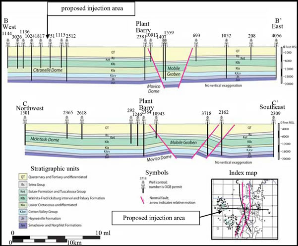
Figure 2. Structural cross sections showing the geometry of the Mobile Graben and Citronelle Dome (from Pashin et al., 2008 [15]).
reservoir at Citronelle is in the Cretaceous-age “Donovan Sand,” which occurs beneath the injection target for CO2 sequestration (the Paluxy Formation). The presence of an active oilfield at Citronelle provided high-density subsurface data for initial geologic characterization in the form of well logs.
Figure 2 shows two geologic cross sections generated as part of a regional assessment of CO2 sequestration potential in southwestern Alabama [17]. Cross section B-B’ shows the regional structural character from the Mobile Graben fault system to the east (where Plant Barry is located) across the Citronelle Dome to the west. Regional dip is less than one degree to the east-southeast towards the Mobile Graben. As such, the injected CO2 will move updip from the injection site to the west-northwest towards the crest of the Dome. No significant faults associated with the Citronelle Dome have been identified in the geologic literature, available surface seismic reflection data, or in the detailed characterization developed for this project [15,17].
Figure 3 shows a general southwest Alabama stratigraphic column that highlights regionally significant Cretaceous through Tertiary-age saline reservoirs and potential
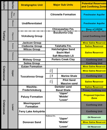
Figure 3. Stratigraphic column for southwest Alabama.
confining units. The proposed injection target is the Paluxy Formation, a fluvial deposit containing 1100 feet (335 meters) of inter-bedded sandstone, siltstone and shale, which occurs at a depth of 9400 feet below ground surface (2865 meters) at the proposed injection site.
A characterization well was drilled in January 2011 (D-9-8 #2) from which whole and sidewall core of the Paluxy Formation were taken and a full suite of openhole geophysical and characterization logs were acquired. Figure 4 shows section of a geophysical log (gamma ray and electrical resistivity) of the upper Paluxy Formation taken from the D-9-8 #2 well. The Paluxy Formation in the injection area can be subdivided into twenty or more potential sandstone injection intervals. Individual sandstone
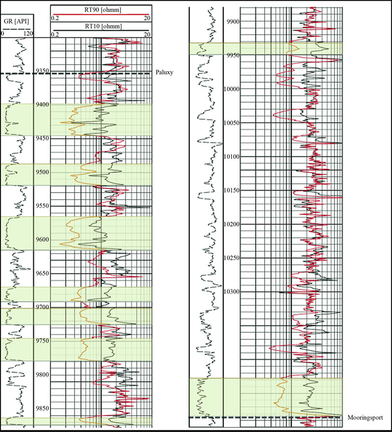
Figure 4. Paluxy formation type log (D-9-8 #2).
units range in thickness from less than 10 feet to over 40 feet (3 meters to over 12 meters). Many of the individual sand layers have a thick central core and are thinner at the periphery.
Whole core analysis and regional geologic studies indicate that the Paluxy represents a fluvial system [18,19]. The upper Paluxy contains several thick sandstones which appear to represent the best targets for injection (Figure 5 and Table 1). Individual sandstones are red or light gray, typically fine upward and contain evidence of periodic subaerial exposure resulting in a high degree of variability in porosity and permeability within the sandstones. Upper Paluxy sandstones are thicker, more porous and have higher average permeability than those in the lower
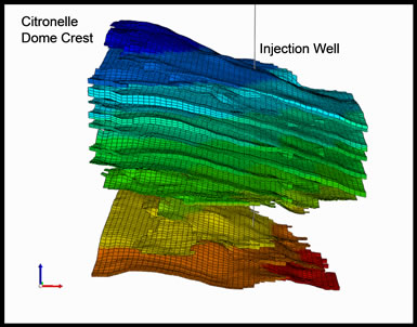
Figure 5. Three dimensional image of the Paluxy formation sand layers.
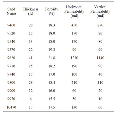
Table 1. Paluxy formation sandstone units.
Paluxy. Lower Paluxy sandstones contain more interbedded mudstone and siltstone and likely represent less attractive injection targets. The lower Paluxy overall contains thicker shale units than the upper Paluxy. The Paluxy Formation was deposited during a major sea level regression in the central Gulf Coast region [20] likely resulting in the overall coarsening upward nature of the unit.
Fine-grained strata, composed of siltstone and mudstone, occur between the sandstone layers in the Paluxy Formation. These low permeability strata will likely contribute to both storage and containment of injected CO2. As such, the reservoir architecture of the Paluxy may allow for better storage conditions because the permeable sands may function as stacked flow units while the fine-grained strata will restrict vertical migration, resulting in a series of “stacked” CO2 plumes with a limited areal extent [21].
Based on the analysis of D-9-8 #2 geological data ten of the thickest and most extensive upper Paluxy sandstone bodies were selected for more detailed characterization and modeling. In all, this represented 210 feet (64 meters) or about 45% of the total net sandstone thickness within the Paluxy Formation (470 feet or 143 meters). Upper Paluxy sandstone porosities range from 10 percent to over 25 percent and permeabilities are highly variable, ranging from 1 millidarcy to over 3000 millidarcies. Average porosity and permeability values for upper Paluxy sandstone units are 19 percent and 200 millidarcies, respectively. Based on these characteristics, it appears that the Paluxy Formation will be capable of accepting the proposed CO2 injection volume (see Reservoir Modeling section below) and may serve as a commercial CO2 storage reservoir in the area.
The proposed confining zone for this CO2 injection test is the basal shale of the Washita-Fredericksburg Group. The Washita-Fredericksburg Group is a coarsening-upward succession of variegated shale and sandstone [22]. Based on detailed geophysical well log interpretation and mapping within the Citronelle Dome, the basal shale of the Washita-Fredericksburg is continuous, and has an average thickness of 150 feet (46 meters). This confining unit has been further characterized during the drilling of the project’s injection wells through core collection and detailed log analysis, with laboratory results still pending.
4. Reservoir Modeling of the Injection Zone
The Computer Modelling Group’s General Equation of state Model—Greenhouse Gas simulation tool (GEMGHG) is a geocellular and geochemistry-based flow model [23]. This simulator was employed to describe the subsurface injection of CO2 into the Paluxy Formation. Based upon interpretation of existing geophysical logs and available core data, a comprehensive description of the subsurface geology was developed for the injection test site area. Primary input parameters for flow modeling included the thickness and elevation of the injection zone, the porosity and permeability of the injection zone, the structural dip at the reservoir horizon, the in-situ reservoir pressure, and temperature, the estimated fracture pressure, the formation water properties, the CO2-brine relative permeability curves and the injectate composition.
While over 20 sandstone units occur within the Paluxy Formation at the test site (Figure 4), only nine sandstone units were selected for injection within the reservoir model. These nine sands were selected based on large thickness and reservoir flow properties, namely permeability and porosity (Table 1). One notable exception was the exclusion of sand 9620 in the injection simulation. Based on log analysis this sandstone unit appears to be the most permeable unit within the Paluxy and it was excluded from the injection simulation to limit the plume’s extent. This was a first order attempt to engineer the injected plume area in order to stay within our designed overall project footprint as the 9620 interval’s permeability was such that it accepted the bulk of the injected CO2. Figure 5 shows a three dimensional image of the sand layers in the model.
Three years of CO2 injection into the Paluxy Formation was simulated at a rate of 500 tonnes per day (total of 547,500 tonnes). The resultant model was then used to establish the project’s regulatory Area of Review (see permitting section). Note that the actual injection will likely be a much smaller volume of CO2 (100,000 to 200,000 tonnes) due to the capture unit operating less than 100 percent of the time. So, the model likely represents an upper limit on the plume’s size. The geophysical simulation results, based on the geologic and reservoir fluid information gathered to date, show that the Paluxy Formation has the capacity to accept the proposed injecttion volume of CO2.
The Paluxy Formation’s thickness and permeability easily allow the injection of CO2 for 3 continuous years into the nine selected sandstone units of this brine-laden reservoir. From this injection simulation, several key findings were made:
1) The plume is slightly oval during the injection period with limited updip migration (Figure 6).
2) Due to higher permeability values and favorable pressure differential, most of the injected CO2 enters the topmost Paluxy sandstone unit.
3) After injection operations cease, the modest dip of the Paluxy Formation influences the migration of CO2 in the up-dip direction. The maximum movement of the CO2 is about 1,600 feet radically in the updip direction at the end of injection operations, which grows to about 2200 feet (670 meters) ten years after injection operations have ceased.
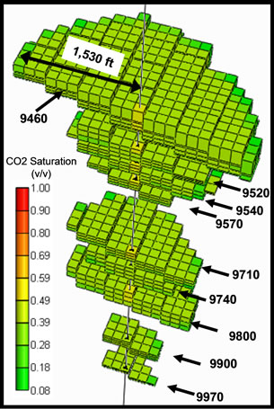
Figure 6. CO2 Plume Development at the end of the three year injection period.
4) The high transmissivity of the Paluxy Formation results in a CO2 plume extent that is greater than the zone of significant pressure build-up. Further, injection pressure decreases rapidly after injection operations are completed. As such, the project’s Area of Review is based on plume extent (since this is greater than the area of pressure buildup).
5) Injection into multiple vertically isolated sand layers enhances natural trapping mechanisms [21], resulting in limited areal extent (approximately 225 acres or 0.9 square kilometers) ten years after injection operations have ceased.
5. Well Construction and Completion
Three new wells were drilled for the injection demonstration, the primary injection well (D-9-7 #2), the backup injector (D-9-9 #2) and the characterization well (D-9-8 #2). The primary goal of the design of these wells is to demonstrate safe injection of CO2 into the injection zone. A complimentary regulatory mandate is to ensure containment of the injection stream within the injection zone and to protect the underground sources of drinking water (USDWs) [24]. Additionally, these wells are designed to be later utilized for CO2-enhanced oil recovery (CO2-EOR) operations following the closure of the CO2 storage project. The CO2 injection wells will be constructed to meet or exceed the Environmental Protection Agency’s recently developed underground injection control (UIC) Class VI CO2 storage well standards [24] as well as the well operator’s (Denbury Onshore, LLC) CO2-EOR injection well standards.
Protected USDWs are defined by the Alabama Department of Environmental Management (ADEM) and the U.S. EPA as aquifers that currently or in the future may supply drinking water for humans or contain water with total dissolved solids (TDS) content less than 10,000 milligrams per liter [24]. The base of the lowermost USDW in the Citronelle Dome occurs at an elevation of approximately –1200 feet (–366 meters) below mean sea level, which corresponds to a depth of about 1400 feet (427 meters) below the ground surface [25].
To ensure a robust containment program, the project wells were drilled using a 13-1/2 inch bit to a depth of 2500 feet below ground surface and cased with 10-3/4 inch J-55 casing. Each well’s surface casing string was cemented in place to surface, which offers protection of the USDW. The remaining interval was then drilled using a 9-7/8 inch drill bit to a total depth of about 11,800 feet. This depth represented the base of the productive oilfield reservoir, the “Donovan Sand” (Figure 3). This hole was then cased with 7-inch L-80 casing and cemented from total depth to the ground surface with a two-stage cement job, which will provide an additional layer of protection across the USDW.
Later, a cast-iron bridge plug with a cement cap will be placed between the Paluxy Formation and the ‘Donovan Sand’ in order to protect the deeper lying casing during injection operations. The wells were completed in the Paluxy’s sandstones using standard perforating charges in selected upper sandstone units, based on their injection characteristics. Injection will occur through tubing (2-7/8” L-80) set in place by a mechanical packer for additional isolation and protection of the long-string casing. For additional protection against corrosion, the tubing was coated with a non-stick, non-scratch polymer (TK-805). The injection well completion schematic is shown in Figure 7.
6. CO2 Monitoring, Verification, and Accounting (MVA)
The Anthropogenic Test MVA strategy is intended to mitigate risk and ensure the safety, integrity and information objectives of the CO2 injection test by: 1) ensuring wellbore integrity; 2) assuring safe CO2 injection operations; 3) verifying the location and migration of the injected CO2 plume; and 4) monitoring for any CO2 leakage. In addition, a series of traditional reservoir characterization tools will be used to further support the MVA efforts. Figure 8 shows the location of planned MVA program components.
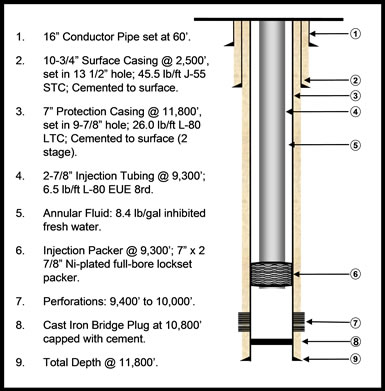
Figure 7. Injection well completion schematic.
Ensuring Injection Well Integrity. Leakage of CO2 along a wellbore is the most likely vertical pathway for CO2 migration from the injection zone into USDW’s or to the ground surface. Cement bond evaluations will be conducted on the characterization and injection wells to ensure that a high-quality cement bond is present across the injection and confining zone intervals and that this bond continues upward and into the surface casing. As required by the Class V UIC permit, annual mechanical integrity testing (MIT) will be conducted on the injectors to ensure that they remain in good operating condition throughout the CO2 injection period. Proof of mechanical integrity includes demonstration that there is no detectable leak in the casing, tubing, or packer and that there is no detectable movement of pollutants from the injection zone through vertical channels adjacent to the injection well bore [26]. The MIT program includes an annular pressure test (internal MIT) and a radioactive tracer survey and temperature log (external MITs). Finally, injecttion tubing and annular pressure will be monitored at the wellhead to ensure casing and tubing integrity throughout the injection.
Verifying the Location and Migration of the Injected CO2 Plume. A variety of MVA methods, including inzone and above-zone pressure monitoring, crosswell seismic, vertical seismic profiling, cased-hole geophysical logging, in-situ fluid sampling, and temperature tools will be used to assess the extent of the CO2 plume. These tools will be deployed in a time-lapse manner to monitor and gain understanding in the temporal dynamics of the CO2 plume migration and to validate/adjust the numerical models to aid in the predictive process. A number of these commercially available tools were deployed, tested and vetted at the Frio Brine and Early Test CO2 injection and storage demonstrations [9,27].
Monitoring in-zone and above-zone pressure serves two purposes. First, monitoring of the in-zone pressure provides direct evidence that the injection zone’s permitted maximum injection pressure is not exceeded, mitigating the risk of fracturing the storage or sealing formations. Second, in-zone and above-zone (above the confining unit) pressure monitoring can provide indications of CO2 migration and/or leakage. One or more existing updip Citronelle Field wells will be used to monitor pressure within the injection interval and another within a saline reservoir located just above the test’s primary confining unit.
Seismic deployments (vertical seismic and crosswell), cased hole geophysical logs (pulsed neutron), and reservoir fluid sampling techniques will be conducted prior to CO2 injection to establish baseline subsurface conditions. These tools will then be run in a time-lapse manner over the injection and post-injection monitoring periods in order to measure the changes in the reservoir conditions that occur as a result of the presence of CO2 within the reservoir.
In addition to the deep monitoring methods discussed above, the Anthropogenic Test site will provide the field test site for the modular borehole monitoring (MBM) system developed by Lawrence Berkeley National Laboratory. The purpose of the MBM system and its field test is to establish the practicality of combining multiple components of experimental CO2 monitoring technology into one integrated monitoring system [28]. The MBM
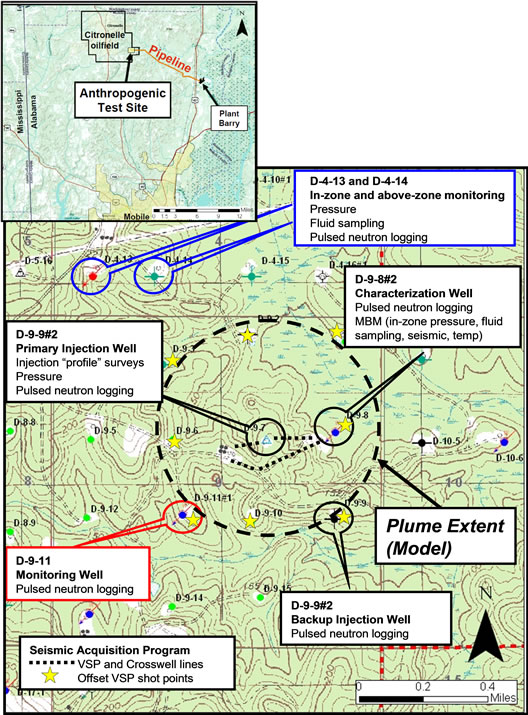
Figure 8. Anthropogenic test site and location of injection and monitoring wells indicating planned MVA deployment.
system will include a dedicated seismic geophone array, a distributed temperature perturbation fiber optic array, and a u-tube reservoir fluid sampling tool. The MBM system will be deployed in the project’s characterization/observation well (D-9-8 #2) and will be used to assess changes in inter-well formation saturation with time, sweep efficiency and CO2-induced changes in the geochemistry of formation fluids. A successful test of this novel MBM system would provide future CO2 injection projects, both storage and those for enhanced recovery operations, a means with which to measure the fate and transport of CO2 in-situ.
Shallow CO2 Leakage Monitoring. Multiple surface monitoring methodologies will be deployed to monitor for shallow or surface CO2 leakage. First, groundwater geochemical sampling will be utilized to monitor for CO2 leakage into USDWs. Groundwater monitoring will focus on 20 metals that the EPA has defined as primary and secondary Maximum Contaminant Levels (MCLs) [29]. Multiple additional geochemical parameters will be measured, including pH, alkalinity and total dissolved solids (TDS).
Groundwater wells, located near the injection well, have been completed in shallow (100-200 ft) and deeper (500 ft) USDWs and will be used to monitor groundwater chemistry. Monitoring of groundwater chemistry in one or more offset oilfield groundwater supply wells will also be conducted. Pre-injection sampling that is currently being conducted will establish the baseline groundwater conditions.
A second surface monitoring method to be employed for the test is to monitor for the presence of perfluorocarbon tracers (PFTs) that will periodically be injected along with the CO2 stream. These PFTs are expected to remain in the CO2 phase and can be detected at multiple orders of magnitude lower concentrations than CO2 [30, 31]. Surface monitoring for the presence of PFTs will occur at various points near the injection site including nearby abandoned and existing wellsites. Finally, soil CO2 flux will be measured at selected locations using flux accumulation chambers in and around the injection site in time-lapse to monitor for anomalous increases of CO2 output from the shallow subsurface.
The proposed testing frequencies for the measurement techniques discussed above are shown in Table 2.
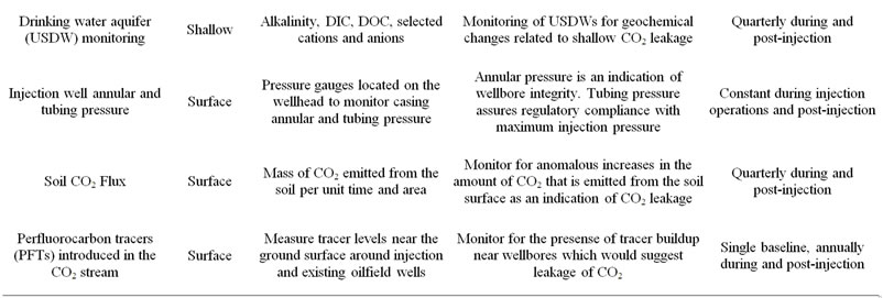
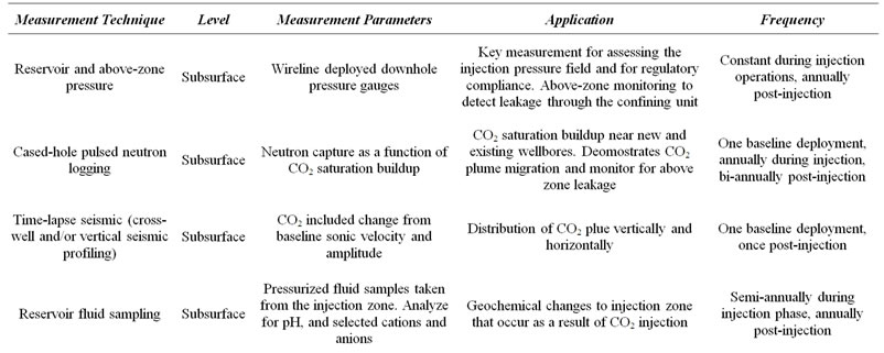
Table 2. Proposed MVA tests and their frequencies.
7. Permitting
Capture Facility Permitting. The Alabama Department of Environmental Management (ADEM) requires an air permit to control and release emissions [32]. Since the Plant Barry carbon capture project includes processes that will control emissions and potentially create new emission points, the project requires an air permit. The project also needed to modify the continuous emissions monitoring systems on the unit providing the slip-stream flue gas (Barry Unit 5) due to the carbon capture process [10].
Transportation Permitting. Crossing of wetlands during construction is universally governed by the Army Corps of Engineers (CoE). The CoE’s authorization is necessary because the project involves the placement of materials into waters of the US, including wetlands under the Corp’s regulatory jurisdiction. A permit was required for the 4-inch pipeline to cross approximately 61,000 square meters (15 acres) of wetlands along the route. The wetland types include open water, scrub/shrub, and forested environments. This permitting process involved preparation of drawings and documentation to support the proposed methods of crossing wetlands within the path of the pipeline. Construction methods available included horizontally drilling under a wetland or “open cutting” where vegetation is removed and silt/storm-water management structures are employed to limit impacts to water quality. Open cutting was typically completed when a drill could not be utilized due to technical difficulties.
In addition to wetlands, the route encountered the federally protected Gopher Tortoise, which is drawn to the open, sandy terrain near the longleaf pinesand is its typical habitat in the vicinity of Plant Barry. Since the pipeline route followed a well maintained and cleared transmission easement for the majority of the route, the presence of tortoises was a strong possibility. Environmental surveys along the route encountered multiple tortoise burrows (over 100) within the proposed 40 foot (13 meter) construction easement. The Fish & Wildlife Service (FWS) required an extensive review and permitting process because the construction had the potential to impact the tortoise.
Similar to crossing of wetlands, horizontally drilling under the tortoises was an attractive option that minimized impact to individual as well as colonies of tortoises. Other options included directing tortoise movement away from active construction areas or temporarily relocating individuals using a federally-licensed contractor. However, the cost of relocating the tortoises was determined to be too high given the large number or tortoises encountered along the right of way. Environmental permitting began in April 2011 and was completed in August 2011.
Storage Permitting. A significant portion of the project team’s effort leading up to well drilling and injection operations has been permitting the storage activities. Three critical permitting activities were required for the well drilling and CO2 injection portion of the project: 1) a USDOE-National Environmental Policy Act (NEPA) Environmental Assessment (EA) [33]; 2) the Army Corps of Engineers permit governing wetland impacts [34]; and 3) ADEM Class V Experimental Well UIC permits for the two injection wells [34]. The purpose of these permits is to ensure that all of the project’s surface and subsurface operations, including well pad development, well drilling, injection, and monitoring, are done in a manner that will not negatively impact the environment and protected drinking waters.
The NEPA process began in early 2010 with the assembly of an EA for the CO2 storage effort. The EA covered the environmental effects (including air quality, surface and subsurface water, land and wildlife impacts), socioeconomic impacts, and cultural resources impacts of the project. After determining that the project’s activities will not have significant environmental consequences or cultural impacts, the DOE issued a Finding of No Significant Impacts (FONSI) in March 2011.
The CoE wetlands permit covering potential impacts resulting from well drilling operations was completed in August of 2011. The project well drilling locations were modified to mitigate any impacts to wetlands. An approximately one acre wetland area was affected by ground leveling and pad expansion operations during drilling location preparations for the characterization well (D-9-8 #2). After the drilling operations were completed the fill was removed and the wetlands were restored. No further wetland impacts are anticipated during injection well site preparations, well drilling, power line construction or pipeline tie-in operations.
The UIC permitting process began in late 2009 with the preparation of permit application materials for the two injection wells. In order to inform the primary regulatory authority, the Alabama Department of Environmental Management (ADEM), the project team made presentations to ADEM on multiple occasions and delivered the first draft of the application to ADEM in December 2010. The process was completed in the fourth quarter of 2011 with the awarding of the injection permits. The ADEM determined that a Class V Experimental Well permit was the appropriate classification for the test’s injection wells. The following are the primary reasons for this determination:
• Short duration of CO2 injection (1 - 2 years);
• Modest volumes of CO2 as compared to “commercial volumes” (less than 2% of Plant Barry’s annual CO2 output);
• CO2 injection under “real world” conditions including dynamic capture and transportation operations (see Integrated Test Plan section);
• Demonstration of innovative and experimental monitoring tools and methods, such as the MBM system.
A 30 day public comment period was opened in August 2011 for the Class V permit draft and extensive comments were delivered from the U.S. Environmental Protection Agency (EPA). The EPA recommended that the permit be modified to meet nearly all of the components of the recently developed EPA UIC Class VI CO2 sequestration well classification established in December 2010 [24]. This effort required a revision of the permit to include a few additional components of the Class VI guidance. Following these alterations, the permit was awarded in November 2011.
It should be noted than many Class VI aspects were already included in the initial Class V application, including extensive site characterization, well construction using CO2 compatible materials, periodic Area of Review (AoR) adjustments based on reservoir modeling and monitoring efforts, a large MVA effort including surface CO2 monitoring, monitoring of the injection and wellbore annular pressure. Following the EPA’s recommenddations, the permit was modified and the following UIC Class VI standards were explicitly stated within the UIC Class V permit:
• Pressurized annulus throughout injection;
• Monthly reporting of injection pressures, annular pressures and injection stream composition;
• Injection stream monitoring;
• Emergency and Remedial Response Plan;
• Periodically updated Corrective Action Plan;
• Open-ended permit duration (project closure is based on USDW non-endangerment demonstration);
• Post-Injection Site Care Plan.
8. Integrated Test Plan
MHI’s advanced amine capture technology, while a proven small-scale success [11], has not been tested at the 25 Megawatt level or on a coal-fired power plant until this project. Therefore, numerous parametric tests are being conducted to rigorously put this technology through its paces. As part of this testing protocol, there will be planned variations in the volume of flue gas processed by the capture system, which in turn will proportionately impact the supply of CO2 available for transport and storage. These variations are expected to occur over time periods ranging from as little as several hours to as much as weeks, with the capture rate ranging from 40% to 100% of process capacity. This may put additional operating constraints on the transportation and storage components of the integrated system due to the resultant variable CO2 rates, pressures and temperatures, emphasizing the need to coordinate design and test specifications between the capture and storage teams. A direct result of this coordination is the need to have a variable-speed injection pump at the injection site to appropriately handle the range in CO2 injection rates.
With CO2 volumes possibly varying within a 24 hour period from 200 tonnes to as much as 550 tonnes per day, the effects of the proposed tests on the capture unit may result in dynamic transportation operations. Maintaining a liquid phase in the pipeline during changes in unit pressure, temperature, or compositional output will require active management of the pipeline’s pressure, volume and temperature (PVT) conditions. Likewise, PVT conditions at the injection pump will have to be actively managed in order to maintain a dense CO2 phase (liquid to supercritical phase) in order to ensure the equipment operates efficiently.
During the testing of the capture facility, it is likely that there will periods of downtime (forced or planned outages) during which the capture facility will not be operational, providing the first insights into the impacts of CO2 supply downtime on transport and injection operations. Management of these periods will be crucial to ensure consistent phase behavior throughout the system as well as minimizing CO2 residency and potential corrosion at key junctures in the system. These downtime periods should also provide opportunities for safety inspecttions of the transportation and injection systems and for the collection of down-hole transient data in the injection and observation wells. This should be useful for understanding the pressure behavior in the storage reservoir during injection and pressure falloff periods.
9. Summary
The “Anthropogenic Test” stands to be the largest demonstration of a fully-integrated pulverized coal-fired CCS project in the United States to date, pulling together components of capture, transportation, subsurface storage and MVA. As a first-of-its-kind demonstration, this test will be very important for understanding the still as yet undefined challenges power plant capture can present to the emerging field of geologic CO2 storage. Currently, this demonstration is completing the permitting phase and preparing for system commissioning and the onset of injection operations. Major project accomplishments to date include:
• The capture unit reached full operational capacity in June 2011.
• Pipeline construction and hydrostatic pressure testing were completed in November 2011.
• A detailed examination of the subsurface geology was completed in 2010, which was uniquely detailed due to the numerous geophysical logs available from existing Citronelle Field well penetrations.
• A characterization well was drilled in January 2011, which provided modern core and geophysical log data that confirmed that the test site represents an attractive location for safe, long-term geological storage of CO2.
• The primary injection and backup injection wells have been drilled and analysis of the collected subsurface core and well log data is ongoing.
• A robust MVA plan has been set forth to monitor and track the CO2 plume’s movement and the associated pressure field in the subsurface. This is currently in a baseline data collection mode.
• Perhaps most importantly, this novel integrated research and demonstration project is developing the multiple permitting pathways required for large-scale integrated storage projects in the United States.
10. Acknowledgements
Denbury Onshore, LLC, owner and operator of the Citronelle Field, is gratefully acknowledged for their essential contribution to this CO2 storage demonstration, particularly Mr. West Richardson, Mr. Gary Dittmar and Mr. Tommy Miller. Further, the project team also acknowledges the cost share and technical expertise provided by the Electric Power Research Institute and Southern Company, without which, this project would still only be a conceptualization. Finally, the project team would like to recognize Ms. Shawna Cyphers for her work constructing the geologic model of the injection site and her editorial work for this paper.
This paper is based upon work supported by the Department of Energy National Energy Technology Laboratory under DE-FC26-04NT42590. This report was prepared as an account of work sponsored by an agency of the United States Government. Neither the United States Government nor any agency thereof, nor any of their employees, makes any warranty, express or implied, or assumes any legal liability or responsibility for the accuracy, completeness, or usefulness of any information, apparatus, product, or process disclosed, or represents that its use would not infringe privately owned rights. Reference herein to any specific commercial product, process, or service by trade name, trademark, manufacturer, or otherwise does not necessarily constitute or imply its endorsement, recommendation, or favouring by the United States Government or any agency thereof. The views and opinions of authors expressed herein do not necessarily state or reflect those of the United States Government or any agency thereof.
REFERENCES
- G. Koperna, D. Riestenberg, R. Petrusak, R. Esposito and R. Rhudy, “Lessons Learned while Conducting Drilling and CO2 Injection Operations at the Victor J. Daniel Power Plant in Mississippi,” 2009 SPE Annual Technical Conference and Exhibition, New Orleans, 4-7 October 2009.
- S. D. Hovorka, et al., “Monitoring a Large Volume CO2 Injection: Year Two Results from SECARB Project at Denbury’s Cranfield, Mississippi, USA,” Energy Procedia, Vol. 4, Proceedings of the 10th International Conference on Greenhouse Gas Control Technologies GHGT10, 19-23 September 2010, Amsterdam, The Netherlands, pp. 3478-3485. GCCC Digital Publication #11-16, 2011.
- J. Lu, P. J. Cook, S. A. Hosseini, C. Yang, K. D. Romanak, T. Zhang, B. M. Freifeld, R. C. Smyth, H. Zeng and S. D. Hovorka, “Complex Fluid Flow Revealed by Monitoring CO2 Injection in a Fluvial Formation,” Journal of Geophysical Research, Vol. 117, 2012, B03208. doi:10.1029/2011JB008939
- T. A. Meckel, S. D. Hovorka and N. Kalyanaraman, “Continuous Pressure Monitoring for Large Volume CO2 Injections,” 9th International Conference on Greenhouse Gas Control Technologies (GHGT-9), Washington DC, 16-20 November 2008, GCCC Digital Publication Series #08-03a.
- J. P. Nicot, J.-W. Choi, T. Meckel, C. Y. Chang, S. D. Hovorka and S. Solano, “Results of Numerical Investigations at SECARB Cranfield, MS Field Test Site,” Eighth Annual Conference on Carbon Capture and Sequestration: DOE/NETL, 11 p. GCCC Digital Publication Series #09-10, 2009.
- R. H. Groshong Jr., J. C. Pashin, M. R. McIntyre, “Structural Controls on Fractured Coal Reservoirs in the Southern Appalachian Black Warrior Foreland Basin,” Journal of Structural Geology, Vol. 31, No. 9, 2009, pp. 874-886. doi:10.1016/j.jsg.2008.02.017
- R. P. Grimm, K. A. Eriksson, N. Ripepi, C. Eble, F. Stephen, S. E. Greb, “Seal Evaluation and Confinement Screening Criteria for Beneficial Carbon Dioxide Storage with Enhanced Coal Bed Methane Recovery in the Pocahontas Basin,” Virginia Original Research Article, International Journal of Coal Geology, Vol. 90-91, 2012, pp. 110-125. doi:10.1016/j.coal.2011.11.002
- S. M. Klara, R. D. Srivastava, H. G. McIlvried, “Integrated Collaborative Technology Development Program for CO2 Sequestration in Geologic Formations,” United States Department of Energy R&D, Energy Conversion and Management, Vol. 44, No. 17, 2003, pp. 2699-2712. doi:10.1016/S0196-8904(03)00042-6
- V. Nunez-Lopez and S. D. Hovorka, “Subsurface Monitoring of Large-Scale CO2 Injection at SECARB’s PhaseIII Cranfield Site,” CMTC 151504, 2012 Carbon Management Technology Conference, Orlando, 7-9 February 2012.
- R. Esposito, R. Rhudy, R. Trautz, G. Koperna and J. Hill, “Integrating Carbon Capture with Transportation and Storage,” Energy Procedia, Vol. 4, 2011, pp. 5512-5519. doi:10.1016/j.egypro.2011.02.537
- S. Kishimoto, et al., “Current Status of MHI’s CO2 Recovery Technology and Optimization of CO2 Recovery Plant with a PC Fired Power Plant,” Energy Procedia, Vol. 1, No. 1, 2009, pp. 1091-1098. doi:10.1016/j.egypro.2009.01.144
- O. Bolland and H. Undrum, “A Novel Methodology for Comparing CO2 Capture Options for Natural Gas-Fired Combined Cycle Plants,” Advances in Environmental Research, Vol. 7, No. 4, 2003, pp. 901-911. doi:10.1016/S1093-0191(02)00085-0
- M. A. Ivie and J. N. Irvin, “CO2 Capture and Sequestration Demonstration Project at an Alabama Power Plant,” 2012 Carbon Management Technology Conference, Orlando, 7-9 February 2012.
- Alabama Natural Heritage Program. List of Rare, Threatened, and Endangered Species and Natural Communities Documented in Mobile County, Alabama, 2009. http://www.alnhp.org/query_results.php
- R. A. Esposito, J. C. Pashin, P. M. Walsh, “Citronelle Dome: A Giant Opportunity for Multi-Zone Carbon Storage and Enhanced Oil Recovery in the Mississippi Interior Salt Basin of Alabama,” Environmental Geosciences, Vol. 15, No. 2, 2008, pp. 53-62. doi:10.1306/eg.07250707012
- E. A. Mancini and T. M. Puckett, “Jurassic and Cretaceous Transgressive-Regressive Cycles, Northern Gulf of Mexico, USA,” Stratigraphy, Vol. 2, 2005, pp. 30-47.
- J. C. Pashin, M. R. McIntyre, R. L. B. Grace, D. J. Hills, “Southeastern Regional Carbon Sequestration Partnership (SECARB) Phase III, Final Report,” Report to Advanced Resources International by Geological Survey of Alabama, Tuscaloosa, 12 September 2008.
- R. Petrusak, D. Riestenberg and S. Cyphers, “Core and Log Analyses for Reservoir Characterization of the Paluxy Formation at Citronelle Dome for the Southeast Regional Carbon Sequestration (SECARB) Partnership Phase III Anthropogenic Test,” Proceedings of the 10th Annual Conference on Carbon Capture and Sequestration, May 2011.
- D. M. Devery, “Subsurface Cretaceous Strata of Mississippi,” Mississippi Department of Natural Resources Information Series 82-1, 1982, 24 p.
- D. Goldthwaite, Ed., “Central Gulf Coast Stratigraphy in Introduction to Central Gulf Coast Geology,” New Orleans Geological Society, 1991, pp. 17-30.
- D. E. Riestenberg, G. J. Koperna, V. A. Kuuskraa and R. A. Esposito, “Using Reservoir Architecture to Maximize CO2 Storage Capacity,” SPE No. 118939, 2008 AAPGSPE Eastern Regional Meeting, Pittsburgh, 11-15 October 2008.
- R. A. Esposito, J. C. Pashin, D. J. Hills and P. M. Walsh, “Geologic Assessment and Injection Design for a Pilot CO2-Enhanced Oil Recovery and Sequestration Demonstration in a Heterogeneous Oil Reservoir: Citronelle Field, Alabama, USA,” Environmental Earth Sciences, Vol. 60, No. 2, 2010, pp. 431-444. doi:10.1007/s12665-010-0495-5
- Computer Modelling Group Ltd., Advanced General Equation-of-State Compositional Reservoir Simulator, 2008 User’s Guide.
- Environmental Protection Agency (EPA), 2011, [EPAHQ-OW-2008-0390 FRL-9232-7] RIN 2040-AE98.
- B. Gillet, D. E. Raymond, J. D. Moore and B. H. Tew, “Hydrogeology and Vulnerability to Contamination of Major Aquifers in Alabama: Area 13,” Prepared by the Geological Survey of Alabama in Cooperation with the Alabama Department of Environmental Management, 2000.
- Alabama Department of Environmental Management Water Division, Water Quality Program, Volume 1, Division 335-6, 2011, ADEM Admin. Code r. 335-6-8-.01.
- S. D. Hovorka, C. Doughty and M. Holtz, “Testing Efficiency of Storage in the Subsurface: Frio Brine Pilot Experiment,” Lawrence Berkeley National Laboratory, 2004. http://escholarship.org/uc/item/8db8500p
- S. Imbus, W. Crow, K. Dodds, M. Briceno, R. Trautz, A. Simone and M. Bohm, “CO2 Capture Project Phase 3 (CCP3) Storage Program: From R&D to Deployment to Contingencies,” 10th Annual Conference on Carbon Capture and Sequestration, Pittsburgh, 2-5 May 2011.
- Environmental Protection Agency (EPA) Office of Water 4606, EPA 816-R-02-025.
- S. D. McCallum, T. J. Phelps, D. E. Riestenberg, B. M. Friefeld and R. C. Trautz, “Interpretation of per Fluorocarbon Tracer Data Collected during the Frio Carbon Dioxide Sequestration Test,” American Geophysical Union Fall Meeting, San Francisco, 5-9 December 2005, Paper GC13A-1214. GCCC Digital Publication Series #05-03f, pp. 1-2.
- A. W. Wells, J. R. Diehl, G. Bromhal, B. R. Strazisar, T. H. Wilson and C. M. White, “The Use of Tracers to Assess Leakage from the Sequestration of CO2 in a Depleted Oil Reservoir, New Mexico, USA,” Applied Geochemistry, Vol. 22, No. 5, 2007, pp. 996-1016. doi:10.1016/j.apgeochem.2007.01.002
- Alabama Department of Environmental Management (ADEM), Major Source Operating Permit (MSOP) 335-3- 16-03.
- US Department of Energy (DOE), “Southeast Regional Carbon Sequestration Partnership Phase III Anthropogenic Test Project (DOE/EA-1785),” 2011.
- US Army Corps of Engineers (COE), Nationwide 12 Permit, Department of the Army Nationwide Permit Verification Number SAM-2011-00509-RCV, Denbury Resources, LLC, Plant Barry to Citronelle Pipeline, 2011.
NOTES
*The original manuscript of this paper was first published in the Proceedings of 28th Annual International Pittsburgh Coal Conference, September 12-15, 2011, Pittsburgh, PA.