International Journal of Modern Nonlinear Theory and Application
Vol.1 No.3(2012), Article ID:23075,12 pages DOI:10.4236/ijmnta.2012.13008
Parametric Study of Dynamic Wrinkling in a Thin Sheet on Elastic Foundation
1School of Aerospace Engineering, University of Cincinnati, Cincinnati, USA
2Mechanical Engineering Department, University of Jordan, Amman, Jordan
Email: alqaisia@ju.edu.jo
Received July 22, 2012; revised August 21, 2012; accepted September 7, 2012
Keywords: Wrinkling; Nonlinear; Elastic Foundation; Sheet Metal; Stability; MMS
ABSTRACT
This work presents an approximate analytical study of the problem of dynamic wrinkling of a thin metal sheet under a specified time varying tension. The problem is investigated in the framework of the dynamic stability of a nonlinear plate model on elastic foundation which namely takes into account the nonlinear mechanics of mid-plane stretching and the dependence of the membrane force on this mechanics. The plate is assumed to be a wide rectangular slab, hinged at two opposite ends and free at the long ends, which can be deformed in a cylindrical shape so that the governing in-plane bending equation of motion takes the same form as that of a beam (e.g. lateral strip) element. An approximate analytical analysis of the beam wrinkling behavior under sinusoidal parametric excitation is carried out by using the assumed single mode wrinkling motion to reduce the beam field nonlinear partial differential equation to that of a single degree of freedom non-linear oscillator. A first order stability analysis of an approximate analytical solution obtained using the Multi-Time-Scales (MMS) method is used to derive a criterion defining critical driving frequency in terms of system parameters for the initiation of wrinkling motion in the thin metal sheet. Results obtained using this criterion is presented for selected values of system parameters.
1. Introduction
Thin elastic sheets with dimensions ranging on length scale from meters to nanometers are encountered in a wide variety of industrial applications such as manufacturing of automotive, electric home appliance, aircraft, thin film depository micro and nano devices etc. In practice, a thin sheet may be subjected to various types of controlled and uncontrolled in-plane and out-of-plane static and dynamic mechanical and thermal loadings during handling, forming and shaping processes and assembly operations. Due to their relatively low flexural stiffness, thin sheets are known to have a tendency to buckle and develop out-of-plane displacement, called wrinkles, despite in some cases a relatively small amount of in-plane compression. The wrinkles are usually along the perpendicular direction to the compressive stress and represent local instabilities that remove the compressive stress. In some cases a limited amount of wrinkling can be tolerated, but there are many cases where wrinkles are unacceptable visual and functional defects. For example, the defect or failure of a thin sheet metal due to wrinkling is of major concern in various traditional metal forming, coating and finishing processes and in the handling, transportation and assembly operations of the finished parts. The wrinkling (or buckling) of a sheet adversely affects its final appearance and functionality. It can play a critical role in implementing certain forming and shaping processes and assembly operations under various static and dynamic loads. And it may also be the most prevalent material instability that places a serious obstacle to the efforts of improving productivity and quality of products and in bringing the economic cost down to a compatible level. On the other hand, controlled wrinkling formation has been considered as a means of creating ordered patterns used in the development of micro/nano devices for micro/nano fluidic applications. Because of the increasing demands for high precision and low cost structures at the macro as well as at micro scales which are free of complex wrinkling patterns, and the interest in the development of controlled wrinkled micro/nanostructures, the problem of elastic/plastic instability in different metal sheet manufacturing processes and micro/nanostructures recently has been the subject of many theoretical, numerical and experimental investigations. There is no intention here to present a literature review on wrinkling and buckling, examples of relevant publications are found in references.
Wrinkling is a general phenomenon generally defined as an elastic/plastic compressive instability (e.g. buckling mechanism, similar to buckling of an elastic column under compression) typically associated with short wavelength deformation patterns (modes), (e.g. mode wavelength is large compared to a sheet element length but small compared to its radii of curvature), whereas overall buckling is essentially a special case of wrinkling in which the half wavelength of the buckling mode is of comparable to that of the sheet element length [1,2]. For example consider a thin sheet, film or web which is essentially under in plane loading. If one of the in-plane principal stress is tensile and the other is compressive with magnitude greater than a critical value (e.g. a value at which flexural stiffness becomes zero), then the sheet metal wrinkles as stated by Wadee and Hunt in [3].
The wrinkling of a sheet metal element may be affected, to various degrees, by a number of factors such as material properties, geometry of the element, material anisotropy, static and time varying contact loads. In addition, this instability behavior may exhibit a wide variation for a small deviation in any of these or other factors. Therefore a unified theory of wrinkling behavior that takes into account the various and complex factors which may affect an elastic/plastic process is difficult to define. Consequently various researchers have used different theoretical and numerical (e.g. finite element) analysis methods to carry out studies on wrinkling behavior and formation tendencies in structural elements of specific geometry under specific loading conditions. This led to a number of different theories on the underlying wrinkling mechanisms and critical values (e.g. criteria) at impending wrinkling. In most of the studies concerned with thin sheet metals or skins of composite sandwich panels, the analyses were based on a 2-D (plane stress or plane strain) formulas, and were carried out, as indicated above, on a case by case for different processes under certain simplifying assumptions concerning the effect of a selected set of system and/or process parameters.
It is noted that wrinkling can be broadly classified, for the purpose of this study, into static and dynamic [4,5]. A static wrinkling is the wrinkling which takes place under static loading conditions, whereas dynamic wrinkling is that which is induced by time varying (dynamic) loads only such as free or forced vibrations.
Studies and models of various aspects of static wrinkling (critical condition at the onset of wrinkling, shape and size of wrinkles) of thin sheet metal and faces of sandwich plates, panels and beams elements are found, for example, in [4-8]. Several of the developed static wrinkling analyses were based on the functional and bifurcation criteria proposed by Hutchinson in [9], where various authors used different plastic deformation theories and yield criteria [1,10-15]. The occurrence of wrinkling was usually presented in the form of a wrinkling limit curve (WLC) in principal stress space. A simplified kinematics (e.g. strain) based approach and a simplified elasticity (e.g. stress) based approach, where the onset of wrinkling is predicted by the solution of an eigenvalue problem were also used by several authors [16-19]. A strain energy based approach was used in [18-20] to analyze wrinkling behavior of anisotropic sandwich panels, sandwich columns, and thin-walled tube with large diameter in an NC bending process, respectively. The critical conditions at the onset of wrinkling were determined by equating the total strain Es associated with an assumed deflection (e.g. wrinkling pattern) to the work W done by forces needed for stable deformation. That is, the equilibrium state is considered to be stable if W > Es, unstable if W < Es and critical if W = Es.
Wrinkling behavior in sheet metal forming has also been studied using finite-element analysis in conjunction with the bifurcation algorithms widely used in buckling problems [2,13,14,21-26]. The various wrinkling analyses using the finite element method can be classified into the two types [23]. The bifurcation analysis [21] of perfect structure and the non-bifurcation analysis employing an assumed initial imperfection in the mesh [13]. It is argued that in a non-bifurcation analysis the introduction of initial imperfections or artifact, sometimes, gives more accurate results than the bifurcation analysis since in practice all real structures have inherent imperfections, such as material non-uniformity, geometric unevenness or undulations [23].
In recent years, the increasing demands for cost effective, and high quality products at high productivity rate manufacturing processes has led to several papers on the subject of wrinkling of sheet metal and sandwich panels under dynamic loadings, e.g. [4,5,27,28]. In most cases these studies are based on simplified linear or non-linear membrane, thin plate or beam models. External (direct), parametric or a combination of direct and parametric excitations were considered, where the parametric excitation generally arise, (e.g. in the case of a beam and a thin plate) by considering the dependence of the axial (e.g. membrane) on the geometric non-linearity which couples the axial displacement with the bending deflection, and/or assuming this force to be an arbitrary time dependent action. In most cases a straightforward elastic/plastic instability (e.g. wrinkling) analysis was used where the onset of this instability was assumed to take place at the system resonance response.
The present work aims at presenting an approximate analytical study of the tendency of a thin metal sheet to wrinkle under a specified time varying tension (e.g. membrane action). Namely, the effect of a dynamic parametric excitation that develops from a time varying tension frequently found in various metal sheets forming and handling operations will be investigated. The tension (the membrane action) will be considered to be a biased sinusoidal time function. The problem will be investigated in the framework of the stability of vibrations of the nonlinear plate model on elastic foundation which namely takes into account the nonlinear mechanics of mid-plane stretching and the dependence of the membrane force on this mechanics. The plate geometry and boundary conditions of the plate will be taken as those that allow the continuous plate model to be reduced to a discrete single degree of freedom nonlinear oscillator similar to that one obtains for the in-plane vibration of a beam element. To this end, the plate will be assumed to be a wide rectangular slab with two opposite free edges while the other two opposite edges are simply supported and thus the plate (slab) deflected surface can take a cylindrical shape with cylinder axis parallel to the plate length [29]. That is, the plate transverse defection is assumed to be independent of the lateral spatial coordinate and thus the governing equation of motion for the plate in-plane bending vibration takes the same form as that of a beam (e.g. lateral strip) element [29]. In the present work the beam model (e.g. thin sheet) will be assumed to be resting on a linear Winkler elastic foundation. It is known that a beam resting on an elastic foundation especially that with an initial geometric unevenness, can exhibit primary and secondary mode dynamic buckling (elastic/plastic instabilities) and complicated defection shapes with localized undulations due to frequency veering [30-32]. An approximate analytical analysis of the beam deflection behavior under sinusoidal parametric excitation will be carried out by using the assumed single mode method whereby the beam field nonlinear partial differential equation is reduced to that of a single degree of freedom non-linear oscillator. The focus will be on the effect of system parameters such as modulus of elasticity, plate thickness, magnitude and frequency of externally applied tension on the onset of dynamic wrinkling and the wavelength of the developed wrinkles due to the parametric dynamic stresses. The critical conditions for the initiation of wrinkles are, as in [4] considered to be those required for the onset of unstable parametric vibration of a single-degree-of-freedom nonlinear oscillator representing a single mode reduced beam model. A first order stability analysis of an approximate first order analytical solution for the parametric response of this oscillator obtained, as in [33], using Multi-Time-Scales (MMS) method [34], is used to derive an expression defining critical driving frequency in terms of system parameters for the onset of wrinkles in the cylindrically deformable thin metal sheet.
2. Physical System and Model Formulation
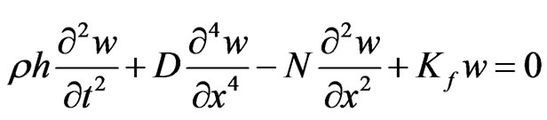
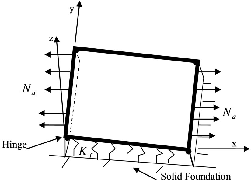
Analysis of the wrinkling behavior of the plate shown in Figure 1(a) is carried out with the aid of the reduced beam model shown in Figure 1(b). The plate is assumed to be a wide rectangular metal sheet of length L (along x coordinate), large width (along y coordinate), small and uniform thickness h, ( ), resting on a complaint linear elastic, Winkler type, foundation of stiffness Kf. It has Young’s modulus E, mass density ρ, points along both of its edges parallel to the y-axis, and free at all points on the two other edges parallel to the longitudinal x-axis. It is assumed that the two lateral boundaries along the y coordinate are subjected to an applied in-plane tension N(t) = N0 + Ntsin(Ωt), where N0 is the spatially averaged steady tension, Nt is the amplitude of a sinusoidal varying, with frequency Ω, tension. The plate is assumed to have a flat rest configuration, and its transverse deflection to be confined to the x-z plane and independent of the lateral spatial coordinate y. Based on these assumptions, the behavior of the plate deflection may be analyzed with the aid of the beam model (e.g. a longitudinal strip element of the plate) shown in Figure 1(b). This beam Equation of motion taking into account the mid-plane stretching and neglecting axial and rotary inertias, may be described by the following partial differential equation [4,29]
 , (1)
, (1)
where N is the in -plane membrane (axial) force per unit width, positive when it produces tension, given by
 (a)
(a) (b)
(b)
Figure 1. System under consideration. (a) A thin plat on winkler foundation hinged at the two opposite sides and free at the other two sides; (b) The corresponding beam model.
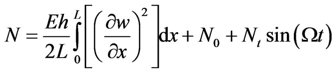 , (2)
, (2)
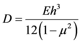
is the plate flexural rigidity, and μ is Poisson’s ratio of the plate material. Equation (1) is, for the present system, supplemented with the following boundary conditions:
W = 0,  at x = 0 and x= L (3)
Note that the above model assumes the beam total deflection is within beam material elastic range. Also as a result of neglecting the axial inertia (e.g. due to static condensation of the axial motion) it is assumed that the effects on the beam deflection of geometric nonlinearity due to mid-plane stretching dominates overt those of nonlinear curvature and inertial nonlinearities. Thus the longitudinal motion becomes the slave of the lateral bending motion whereby the axial force N which gives rise to the nonlinear term in partial differential Equation (1) becomes a nonlinear function of the time variable only and is independent of the independent spatial variable x. In other words, the static version of Equation (1), obtained by omitting the leading inertia term in this Equation and the time varying part of the applied axial force Ntsin(Ωt), is a an ordinary linear differential Equation with constant coefficients where N is unknown constant, as given by Equation (2) after omitting the time varying part in this Equation, dependent on the actual unknown deflection w. Because of the dependence of the constant coefficient N on the unknown deflection w a solution to the linear static version of Equation (1) can only be obtained approximately using, for example, an iterative procedure. It is noted that by assuming a harmonic in time variation for the beam deflection in Equation (1), one obtains an equivalent linear differential in space Equation with constant coefficients one of which is dependent on the unknown beam deflection, similar to the corresponding static version, which can only be solved approximately, using an iterative procedure, for the mode shape deflections and corresponding natural frequencies. Such procedure will in the present case results in prohibitively complicated implicit frequencymode shape Equations that deny reasonably elaborate numerical solution. In the present work an approximate solution to Equation (1) will be obtained using the assumed linear mode method for the wrinkling motion, which despite its known inherent limitations may lead to useful information about the beam dynamic wrinkling behavior.
3. Dynamic Wrinkling Analysis
The stability of the beam system described by Equation (1) against a dynamic wrinkling pattern may be examined by determining the conditions leading to unstable vibration amplitude of the associated discrete temporal problem [4]. Accordingly, inserting into Equations (1) and (2) a wrinkling pattern of the form
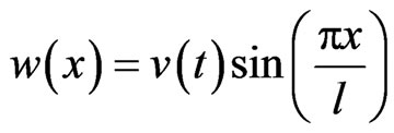 , (4)
, (4)
where 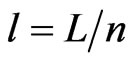 is unknown wrinkle length, n is unknown wave number, L is the beam (e.g. plate) length, and v is a time varying amplitude. Substituting for Equation (4) into Equations (1) and (2) leads to the following parametrically excited Duffing type oscillator:
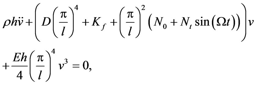 (5)
(5)
Next, the following dimensionless variables and parameters are introduced:
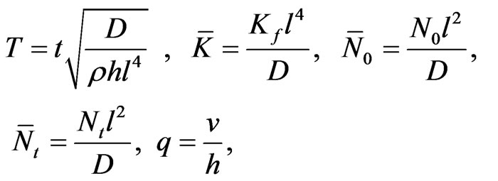 , (6)
, (6)
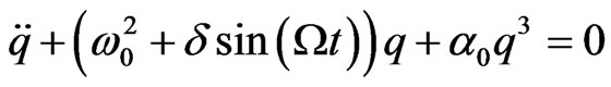
then, Equation (5) takes the following dimensionless form:
 , (7)
, (7)
where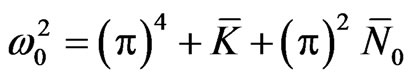 ,
,  , and
, and
 . The general class of the nonlinear parametrically excited oscillator in Equation (7), as well as its linear version (e.g. the case when α0 = 0), which are found in many practical applications, do not admit a closed form solution. Descriptions of the behavior of this type of oscillators, as well as that of its linear version, are found in many periodical references and several nonlinear text books [33,34]. These descriptions were obtained using the nonlinear theory approximate analytical methods such as the perturbation Linstedt-Poincare, Multi-Time Scales, Harmonic Balance, Light-Hill expansion as well as numerical and Floquet theory stability analysis. These studies indicate that the nonlinear oscillator in Equation (7), as well as its linear version can, depending on range of system parameters, exhibit in addition to the trivial solution various types of dynamic response behaviors such as stable or unstable periodic, and non periodic responses, which may bifurcate from the trivial solutions of the linear version. The description of the behavior of this type of oscillators is usually presented in the form of stability boundary curves separating regions of stable and unstable solutions in the parameter Ω-δ space. The analysis of the linear version of Equation (7) provides the instability boundaries that separates stable from unstable trivial solutions. Then analysis of the nonlinear form of the system examines the limit cycles and nontrivial periodic and aperiodic solutions which may bifurcate from the trivial solutions. It is noted that the instability curves divide the Ω-δ parameter space into a number of stability-instability regions emanating from different and widely spaced points on the Ω axis. From practical point of view the principal (i.e. the first) of these regions is the most important one because it is not significantly affected by damping and it corresponds to the lowest and broadest range of the driving frequencies. For frequencies below this range the trivial solution remains stable, while for a driving frequency above the critical value corresponding to the boundary of the principal instability region is expected to develop [33,34]. Obviously wrinkling vibrations may also develop as the frequency is increased and enters higher regions of instabilities, but as indicated above the primary instability is usually the most dangerous one; therefore the focus of this work will be on this region.
4. Dynamic Wrinkling Instability Regions
The focus of the present analysis, as indicated above, is to determine an approximate solution to the primary region instability curves of the wrinkling vibrations of the parametrically excited beam system described by Equation (7). Such an approximate solution may be obtained using one of the well known approximate methods such as Harmonic Balance (HB) or the MultiTime-Scales (MMS) described in [34]. In this work an approximate expression for the critical forcing frequency for onset of wrinkling is derived following closely a first order MMS solution and stability analysis presented in [33].
Multi-Time Scales (MMS) Solution
In obtaining an approximate solution to Equation (7), or its linear version, using the MMS solution one assumes a power series expansion for the parameter δ of the form
 , (8)
, (8)
where ε is a positive small ( ) gauge parameter, used only for bookkeeping . Then following the standard steps of the MMS analysis one rescales the nonlinear and the forcing terms ( as well as damping if present) in Equation (7) so that they appear at the same of order of ε. Next one lets Ω = 2ω0 + εσ, where σ is frequency detuning parameter, and assumes a power series solution of the form of
 , (9)
, (9)
where Tp = εpt, p = 0, 1, … Are independent time scales variables. Upon making the above substitutions into Equation (7), and equating independently in the resulting Equation the coefficients of different powers of ε to zero one obtains a hierarchy set of linear partial differential Equations which are then solved sequentially for q0, q1, … Solving a desired number of these linear Equations, and imposing the periodicity condition by eliminating secular ( resonance producing) terms which arise in the forcing terms of these Equations, leads to, respectively, the following zero order, (e.g. on the T1 time scale), solution and steady state frequency relation, for more details see references [33,34]
 , (10)
 , (11)
where
 , (12)
 is the complex conjugate of C, a is the steady state amplitude, and a(T1, T2, ···) and f(T1, T2, ···) denote a slowly varying amplitude and phase, respectively, for which the steady state solutions a , (Equation (11)), and f provide the amplitude , and phase of a periodic solution to Equation (7). Note that Equation (11) shows that the trivial solution (a = 0) is always a solution, while the nontrivial solutions can be expressed as
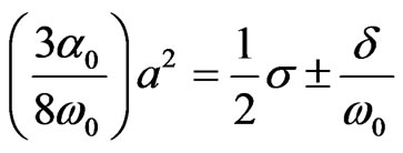 , (13)
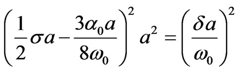
provided that a is real, e.g.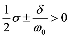 .
.
The stability of the above nontrivial solutions can be also be determined by examining the eigenvalues of the linearized amplitude and phase modulation Equations about the corresponding steady state values. In general the results of stability analysis are presented in the excitation amplitude δ-detuning parameter σ plane. The primary stability region typically shows three distinct types of behavior as illustrated in Figure 2, found in [33,34]. In region I only stable trivial solutions exist and the system response, regardless of starting conditions, decays to zero. In region II, the trivial solution is unstable and co-exits with a stable nontrivial limit cycle solution; thus for all starting conditions the steady state solution is a limit cycle. In Region III, the trivial solution becomes stable and co-exists with two nontrivial stable periodic solutions. In this case, depending on the starting conditions, the steady state solution may decay to zero or settles into one of the periodic attractors whose amplitude is determined by Equation (13). It is noted that a more
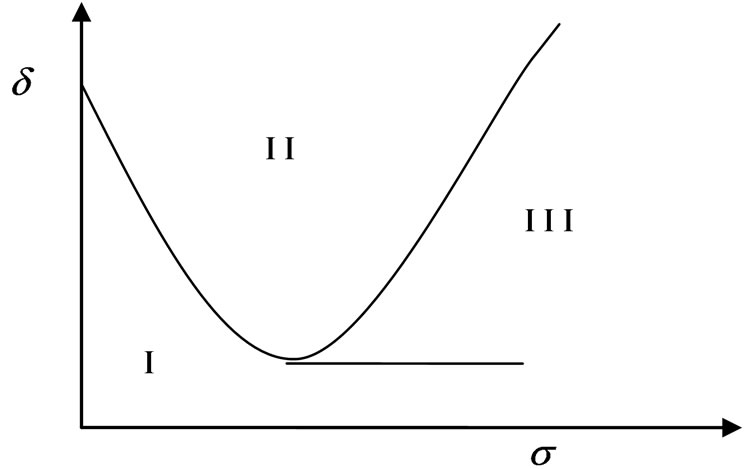
Figure 2. Stability regions of periodic solutions of Equation (7) [43].
detailed bifurcation analyses may reveal other bifurcation scenarios which, for the sake of simplicity, are not explored. Also an exact analytical solution to region III transition curves in the form δ(Ω) or Ω(δ) is not feasible; these transition curves are usually determined numerically using Floquet theory or Light-Hill expansion [34].
Based on the above description of stability characteristics of the response of the oscillator in Equation (7), the critical conditions for the onset of wrinkles of waveform described by Equation (4) are taken to be as those corresponding to the transition curves of the principal instability region III which, to first order approximation [33,34], and after substituting for the definition of the relevant system parameters given in section (3), leads to the critical driving frequency Ωc expression:
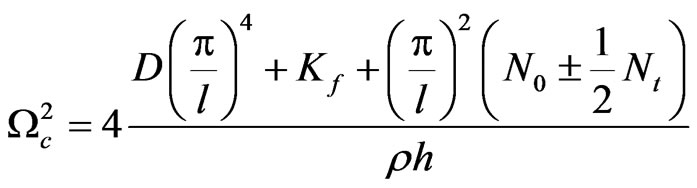 , (14)
For a driving frequency above Ωc the wrinkling vibrations that are expected to develop correspond to the smaller of the two squared frequency values in Equation (14). The wavelength of the wrinkle l, obtained by minimizing the smaller squared frequency in Equation (14) with respect to l, is given by Birman [4]
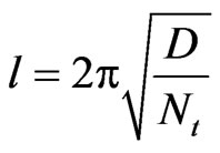 , (15)
5. Results and Discussion
The present study of the stability of a thin sheet metal stability against the buildup of wrinkling vibrations is based on the approximate critical frequency criterion presented in Equation (14). It is noted that , as can be seen from Equation (5), for the present hinged-hinged and initially flat beam model there is no possibility of frequency curve veering (e.g. two frequencies, e.g. lowest two eigenvalues, become nearly equal) and mode localization; that is, the linear natural frequencies which are given by
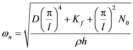 , (17)
remain well separated as the system parameters are varied over their range. Also, the linear natural frequency expression above shows that when the applied axial force is tensile, e.g. N0 > 0, static buckling of the beam is not possible. It to be noted however that these behaviors of the present hinged-hinged beam resting on a Winkler foundation and free of externally applied lateral loads are not shared with other cases when this beam it not initially flat and/or has different end supports and/or an external lateral load. In such cases, i.e. when the beam is hinged at one or both ends to a torsional spring with or without an external lateral load and initial imperfection (e.g. not initially flat), it is possible, depending of the system parameters, for the beam to posses frequency curve veering, and mode localization even when the axial force is a tensile type, as stated in [30-32].
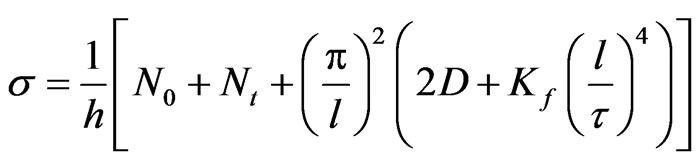
It is to be noted that when the amplitude of time varying part of the applied axial Nt is not zero, Equation (14) yields two values for the critical driving frequency Ω. As indicated in the previous section, the smaller of these two frequency values, termed Ωc, obtained by selecting the negative sign of the last term in the numerator of this Equation , is the more important one. Figures 3-10 display examples of obtained results using Equation (14) for the variation of Ωc with selected system parameters. These results are for an aluminum alloy plate having mass density ρ = 2700 (kg/m3), Young’s modulus E = 61 (Gpa), Poisson’s ratio μ = 0.25 yield stress σy = 90 (Mpa), and ultimate tensile strength σμ = 190 (Mpa). For given plate thickness h, length L and number of wrinkles n, Equation (15) is used to calculate the required dynamic axial force amplitude Nt where the wrinkle length l is calculated using the relation L= nl. This was done in order to obtain an integer number of wrinkles so that the assumed wrinkle waveform in Equation (1) satisfies the prescribed boundary in Equation (3). It is noted that the present results in Figures 3-10 are for the case where the total normal stress σ does not exceed the material yield strength σy, where the normal stress is obtained using the relation
 (18)
(18)
From the sample results presented in Figures 3-10 one can see that for the present system increasing system stiffness, e.g., increasing plate thickness, foundation stiffness, plate material modulus of elasticity and the static axial tensile force tends to increase the plate stability against the buildup of wrinkling vibrations.
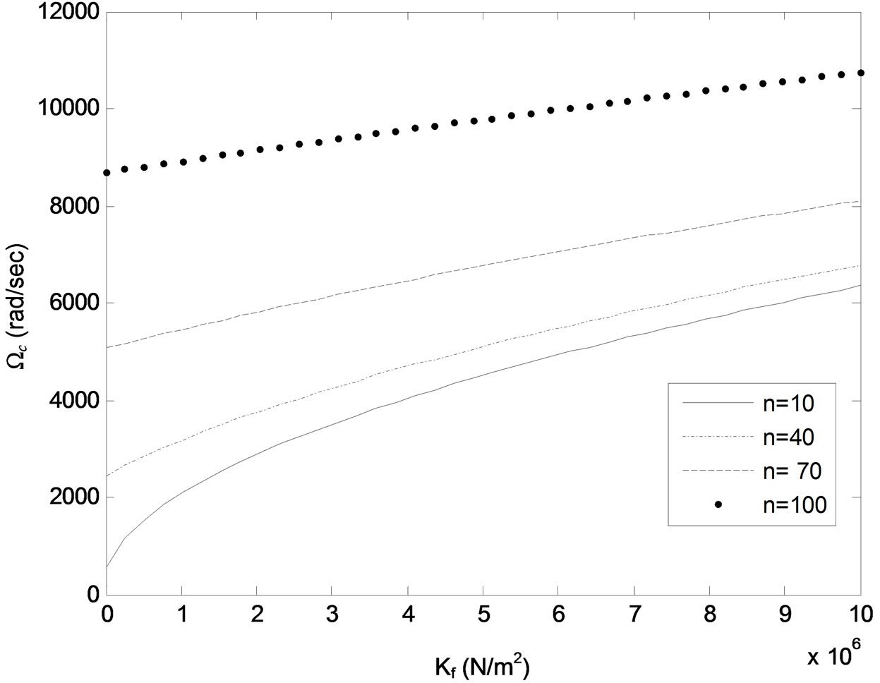
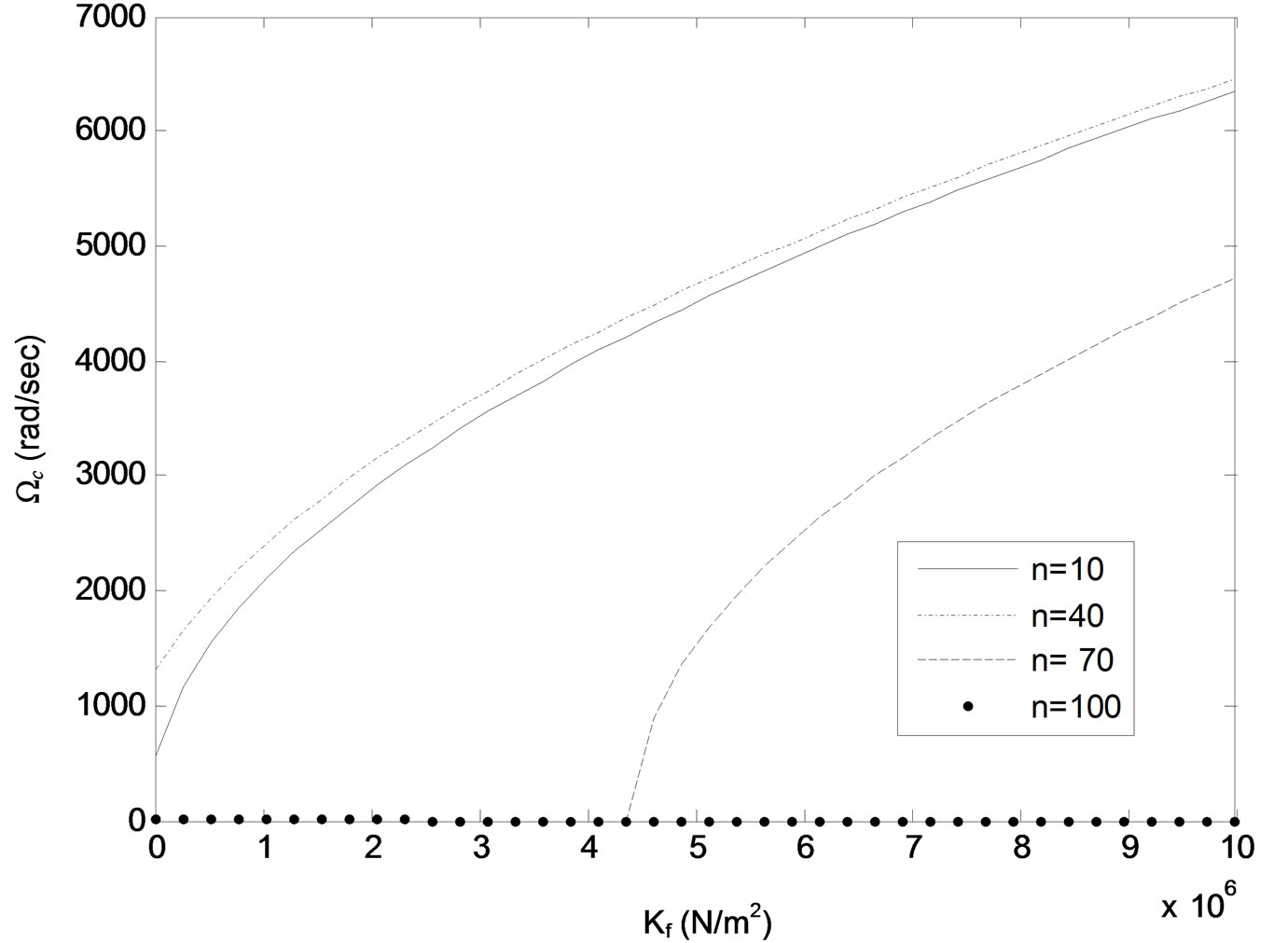
Figure 3. Critical driving frequency Ωc versus foun dation stiffness Kf for different number of wrinkles n. Plate thickness h = 0.24 mm, static tension N0 = 50 N.
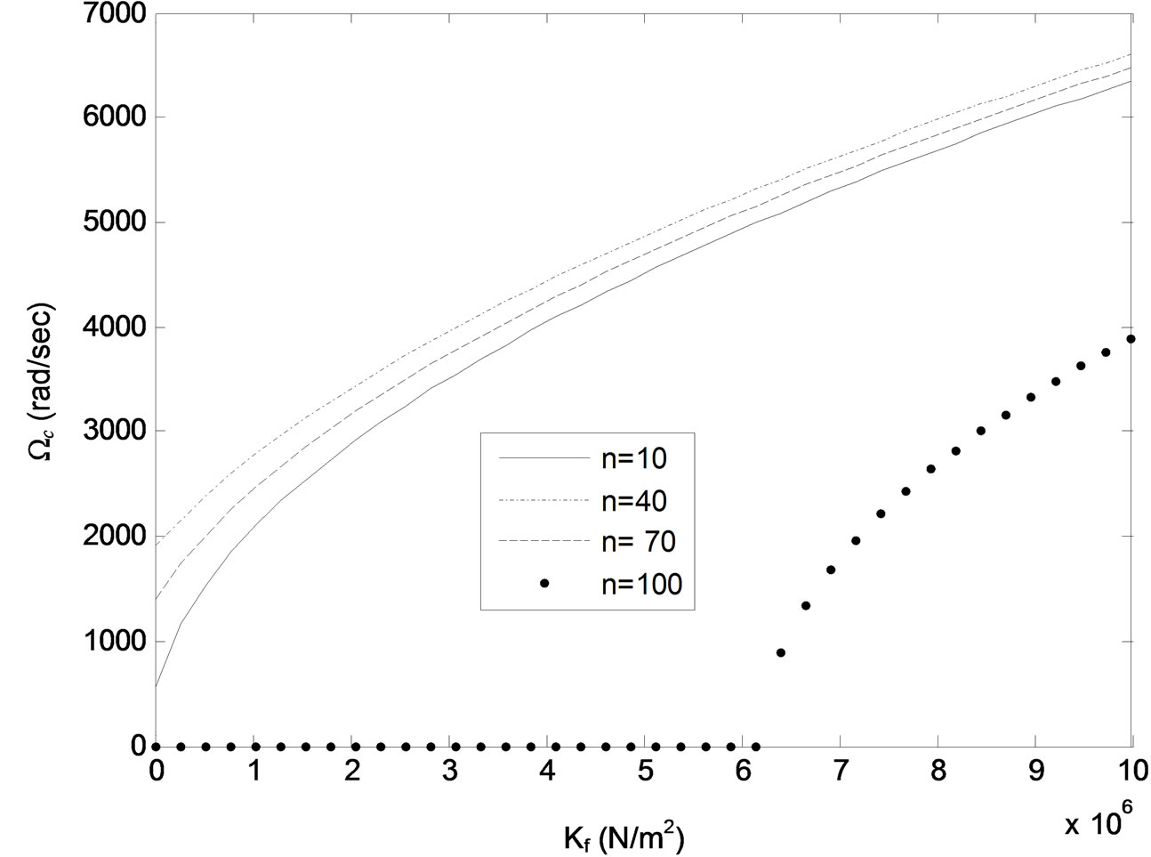
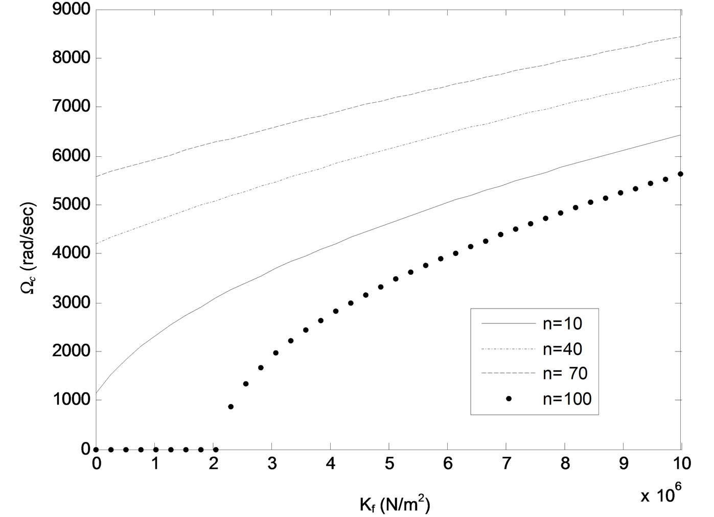
While, on the other hand, this stability decreases by increasing the dynamic axial tensile force and the number of wrinkles above some critical values of the system parameters. For example, comparing Figures 3 and 4 it can be seen that as the plate thickness is changed from h = 0.24 mm Figure 3 to h = 0.23 mm Figure 4 while keeping values of other system parameters constants, the wrinkles number n , ( , l = wrinkle half wavelength, L = beam length), passes through a critical value nc, 70 < nc < 100, where all wrinkles of length shorter than
  become unstable for values of foundation stiffness Kf below a critical value
(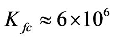 N/m2 for the case in Figure 4). However, as Kf is increased above this critical value, the critical frequency Ωc tends to increase but remains well below its value for n < nc. Comparing Figures 5 and 6 to Figures 3 and 4 it can be seen that decreasing the plate thickness h and/or axial tension N0 tends to decrease the value of the critical wrinkles number nc. These trends are illustrated further in Figures 7-9, which show critical
values of thickness h and static axial tension N0 below which the beam (e.g. plate) becomes unstable against the buildup of wrinkling vibrations of any length at any parametric excitation frequency Ω. Finally, Figure 10 indicates that for given system parameters, the critical frequency Ωc tends to increase with number of wrinkles n up to a maximum value of n (e.g. optimum beam length against build up of unstable wrinkling motions) then tends to decrease as n is further increased until it reaches zero, beyond which the plate becomes unstable against the buildup of wrinkling motion of any length at any driving frequency.
As indicated above, the present results which are based on using a simplified model, approximate first order analytical solution and first order stability analysis. Obviously a more rigorous stability analysis and other boundary conditions should be considered before one can make more reliable and general conclusions about the
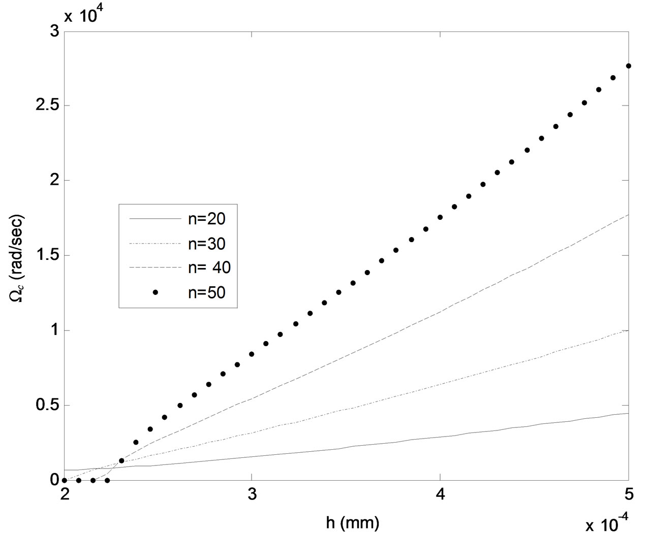
Figure 7. Critical frequency Ωc versus plate thickness h for different values of number of wrinkles n. Kf = 103 N/m2, N0 = 30 N.
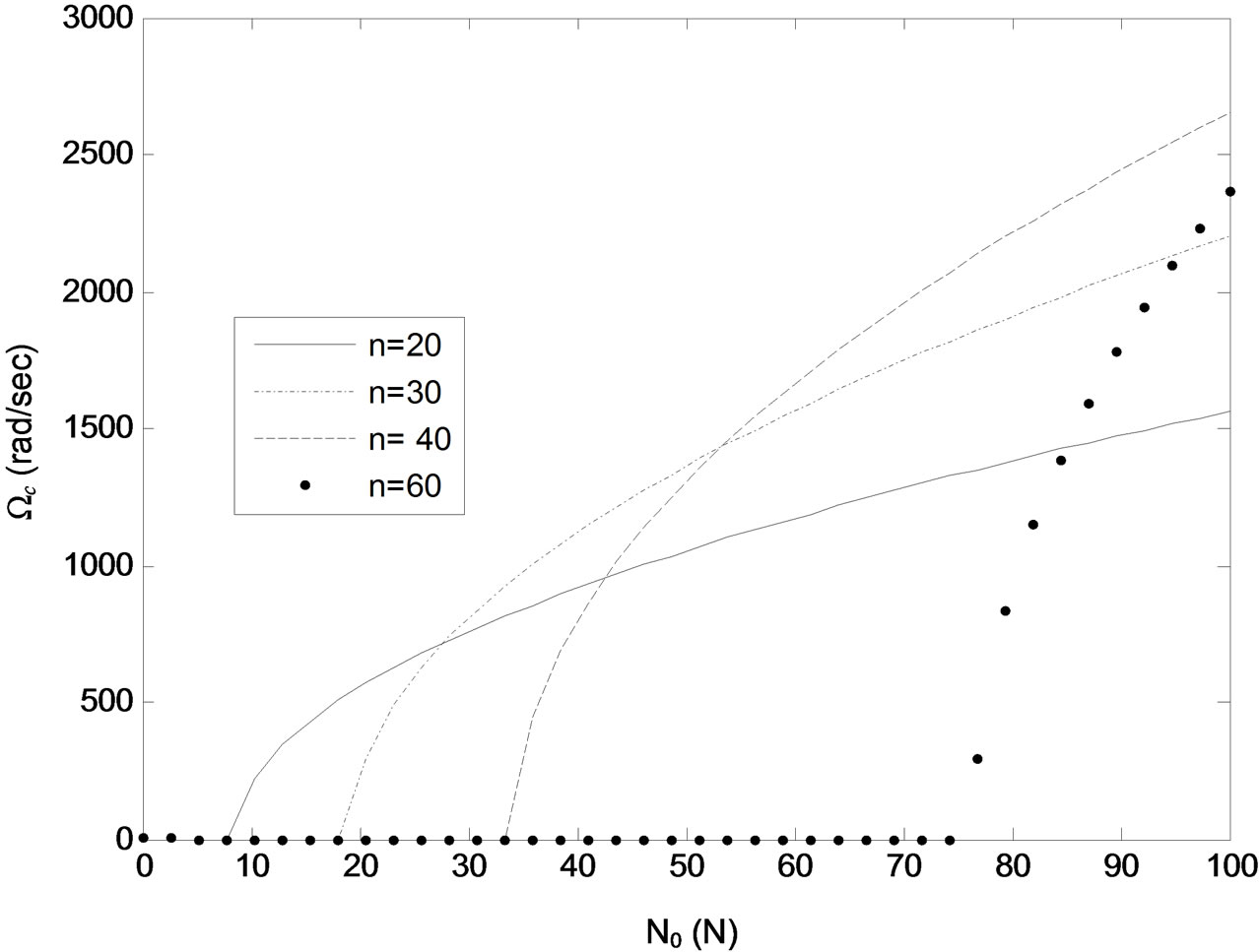
Figure 8. Critical frequency Ωc versus static axial lada N0 for different values of wrinkles number n. Kf = 103 N/m2, h = 0.22 mm.
wrinkling behavior of a thin metal sheet.
6. Conclusion
The present work has shown that it is possible, depending on system parameters, to initiate wrinkling motion in a thin, cylindrically deformable plate, hinged at two opposite ends, free of supports at the other two ends, resting on a Winkler foundation and subjected to a time varying tension force if the plate is driven by this force into a parametric resonance. The present results are based on a first order approximate stability analysis of MathieuDuffing type nonlinear oscillator in Equation (7). Obviously a more rigorous study investigates a higher order stability analysis of this equation, a wider range of sys-
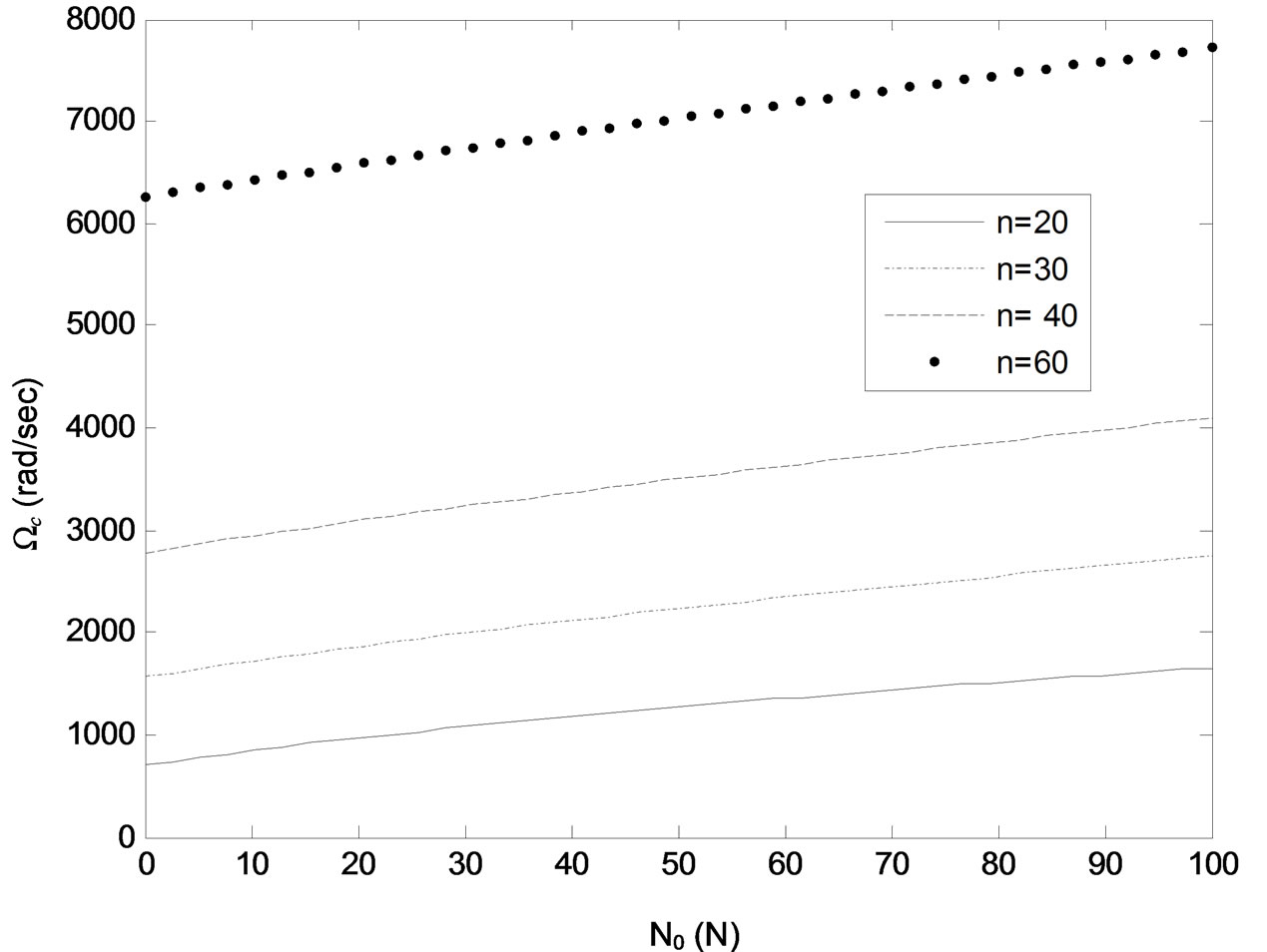
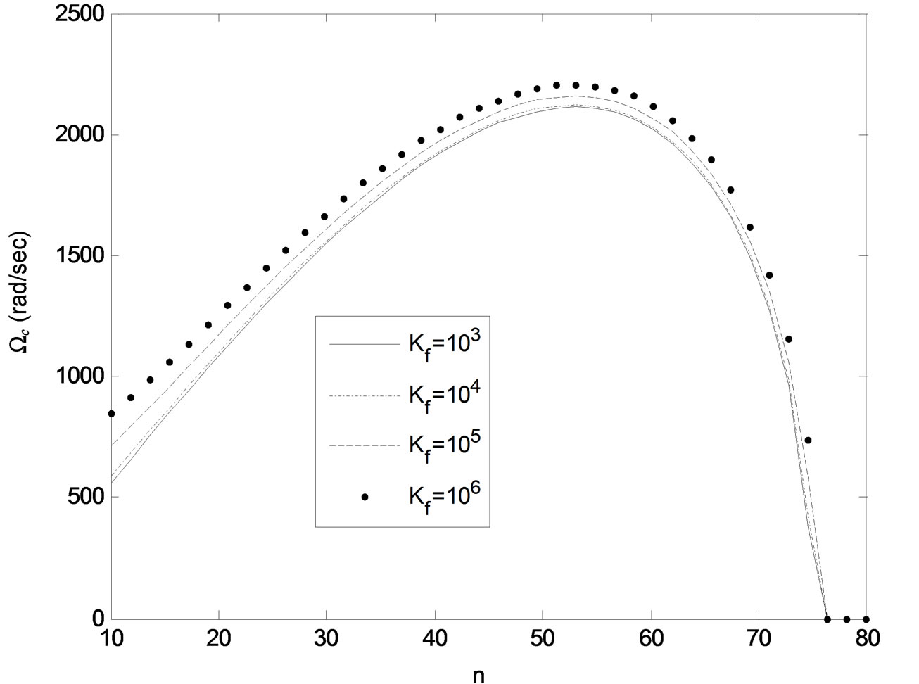
Figure 10. Variation of critical frequency Ωc with number of wrinkles n. h = 0.23 mm, N0 = 50 N.
tem parameters and other more complicated boundary conditions. For the present initially flat configuration, hinged-free-hinged-free boundary conditions and parametric loading conditions, frequency curve veering and mode localization are not likely to occur. It is known that at a frequency veering a continuous system can undergo complicated dynamics and mode localization that can initiate complicated patterns of wrinkles. To the author knowledge studies on the effect of frequency veering on the wrinkling behavior of continuous structures are not found in the open literature.
REFERENCES
- P. Tugcu, K. W. Naele, P. D. Wu and S. R. Mac Ewen, “Effect of Planar Anisotropy on Wrinkling Formation Tendencies in Curved Sheets,” International Journal of Mechanical Sciences, Vol. 43, No. 12, 2001, pp. 2883- 2897. doi:10.1016/S0020-7403(01)00065-0
- H. Lu, H. S. Cheng, J. Cao and W. K. Liu, “Adaptive Enrichment Meshfree Simulation and Experiment on Buckling and Post Buckling Analysis in Sheet Metal Forming,” Computer Methods in Applied Mechanics and Engineering, Vol. 194, No. 21-24, 2005, pp. 2569-2590. doi:10.1016/j.cma.2004.07.046
- M. A. Wadee and G. W. Hunt, “Interactively Induced Localized Buckling in Sandwich Structures with Core Orthotropy,” Transactions of ASME Journal of Applied Mechanics, Vol. 65, 1998, pp. 523-528.
- V. Birman, “Dynamic Wrinkling in Sandwich Beams,” Composites Part B: Engineering, Vol. 35, No. 6-8, 2004, pp. 665-672. doi:10.1016/j.compositesb.2003.08.012
- J. Hohe, L. Librescu and S. Y. Oh, “Dynamic Buckling of Flat and Curved Sandwich Panels with Transversely Compressible Core,” Composite Structures, Vol. 74, No. 1, 2006, pp. 10-24. doi:10.1016/j.compstruct.2005.03.003
- H. Hassani and K. Neale, “On the Analysis of Sheet Metal Wrinkling,” International Journal of Mechanical Science, Vol. 33, No. 1, 1991, pp. 13-30. doi:10.1016/0020-7403(91)90024-W
- B. Davidovitch, R. Schroll, D. Vella, M. Adda-Bedia and E. Creda, “Prototypical Model for Tensional Wrinkling in Thin Sheets,” Applied Physical Sciences, Vol. 108, 2011, pp. 18227-18232.
- Y. Mei, S. Kiravittaya, S. Harazim and O. G. Schmidt, “Principles and Applications of Micro and Nanoscale Wrinkles,” Materials Science and Engineering: Reports, Vol. 70, No. 3-6, 2010, pp. 209-224. doi:10.1016/j.mser.2010.06.009
- J. W. Hutchinson, “Plastic Buckling,” Advances in Applied Mechanics, Vol. 14, 1974, pp. 67-144. doi:10.1016/S0065-2156(08)70031-0
- J. W. Hutchinson, “Post-Bifurcation Behavior in the Plastic Range,” Journal of the Mechanics and Physics of Solids, Vol. 21, No. 3, 1973, pp. 163-190. doi:10.1016/0022-5096(73)90017-3
- K. W. Neale and P. Tugcu, “A Numerical Analysis of Wrinkling Formation Tendencies in Sheet Metals,” International Journal of Numerical Methods in Engineering, Vol. 30, No. 8, 1990, pp. 1595-1608. doi:10.1002/nme.1620300816
- J. Cao, “Prediction of Plastic Wrinkling Using the Energy Method,” Transactions of ASME Journal of Applied Mechanics, Vol. 66, 1999, pp. 646-652.
- J. Cao and M. Boyce, “Wrinkling Behavior of Rectangular Plates under Lateral Constraint,” International Journal of Solids and Structures, Vol. 34, No. 20, 1997, pp. 153- 176. doi:10.1016/S0020-7683(96)00008-X
- Y. Kim and Y. Son, “Study on Wrinkling Limit Diagrams of Anistropic Sheet Metals,” Journal of Materials Processing Technology, Vol. 97, No. 1-3, 2000, pp. 88-94. doi:10.1016/S0924-0136(99)00346-5
- J. P. De Magalhaes Correia and G. Ferron, “Wrinkling of Anisotropic Metal Sheets under Deep-Drawing: Analytical and Numerical Study,” Journal of Materials Processing Technology, Vol. 155-156, 2004, pp. 1604-1610. doi:10.1016/j.jmatprotec.2004.04.270
- A. S. Benson and J. Mayers, “General Instability and Face Wrinkling of Sandwich Plates—A Unified Theory and Applications,” American Institute of Aeronautics and Astronautics Journal, Vol. 5, No. 4, 1967, pp. 729-739.
- C. C. Lin and C. D. Mote, “Eigenvalue Solutions Predicting the Wrinkling of Rectangular Webs under NonLinearly Distributed Edge Loading,” Journal of Sound and Vibration, Vol. 197, No. 2, 1996, pp. 179-189. doi:10.1006/jsvi.1996.0524
- B. K. Hadi and F. L. Matthew, “Development of BensonMayers Theory on the Wrinkling of Anisotropic Sandwich Panels,” Composite Structures, Vol. 49, No. 4, 2001, pp. 425-434. doi:10.1016/S0263-8223(00)00077-5
- B. K. Hadi, “Wrinkling of Sandwich Column: Comparison between Finite Element Analysis and Analytical Solutions,” Composite Structures, Vol. 53, No. 4, 2001, pp. 477-482. doi:10.1016/S0263-8223(01)00060-5
- H. Li, H. Yang, M. Zhan and R. J. Gu, “A New Method to Accurately Obtain Wrinkling Limit Diagram in NC Bending Process of Thin-Walled Tube with Large Diameter under Different Loading Paths,” Journal of Materials Processing Technology, Vol. 17, No. 1-3, 2006, pp. 192-196. doi:10.1016/j.jmatprotec.2006.03.191
- X. Wang and L. H. N. Lee, “Postbifurcation Behavior of Wrinkles in Square Metal Sheet under Yoshida Test,” International Journal of Plasticity, Vol. 9, 1993, pp. 1-19.
- H. S. Lee, D. W. Hung, J. H. Jeong and S. Im, “Finite Element Analysis of Lateral Buckling for Beam Structures,” Computers and Structures, Vol. 53, No. 6, 1994, pp. 1357-1371. doi:10.1016/0045-7949(94)90400-6
- J. B. Kim, D. Y. Yang, J. W. Yoon and F. Barlat, “The Effect of Plastic Anisotropy on Compressive Instability in Sheet Metal Forming,” International Journal of Plasticity, Vol. 16, No. 6, 2000, pp. 649-676. doi:10.1016/S0749-6419(99)00064-9
- C. Loganathan and R. Naryaanasamy, “Effect of Mechanical Properties on the Wrinkling Behavior of Three Different Commercially Pure Aluminum Grades When Drawn through Conical Tractrix Dies,” Materials Science and Engineering: A, Vol. 406, No. 1-2, 2005, pp. 229-253. doi:10.1016/j.msea.2005.06.037
- J. L. Grenestedt and J. Reany, “Wrinkling of Corrugated Skin Sandwich Panels,” Composites Part A, Vol. 38, No. 2, 2007, pp. 576-589. doi:10.1016/j.compositesa.2006.02.007
- E. S. Lee and S. K. Youn, “Finite Element Analysis of Wrinkling Membrane Structures with Large Deformations,” Finite Elements in Analysis and Design, Vol. 42, No. 8-9, 2006, pp. 780-791. doi:10.1016/j.finel.2006.01.004
- G. P. Dube, P. C. Dumir and A. Mallik, “Dynamic Buckling of Laminated Thick Shallow Sphere Cap Based on a Static Analysis,” Mechanical Research Communications, Vol. 27, No. 5, 2000, pp. 561-566. doi:10.1016/S0093-6413(00)00130-0
- D. S. Lee, “Nonlinear Dynamic Buckling of Orthotropic Cylindrical Shell Subjected to Rapid Loading,” Journal of Engineering Mathematics, Vol. 38, No. 2, 2000, pp. 141-154. doi:10.1023/A:1004729816574
- S. Timoshenko and S. Woinowsky-Krieger, “Theory of Plates and Shells,” McGraw-Hill, New York, 1987.
- R. H. Plaut and E. R. Johnson, “The Effect of Initial Thrust and Elastic Foundation on the Vibration Frequencies of a Shallow Arc,” Journal of Sound and Vibration, Vol. 78, No. 4, 1981, pp. 565-571. doi:10.1016/S0022-460X(81)80125-3
- W. Lacarbonara, H. N. Arafat and A. H. Nayfeh, “Large Non-Linear Interactions in Imperfect Beams at Veering,” International Journal of Non-linear Mechanics, Vol. 40, No. 7, 2005, pp. 987-1003. doi:10.1016/j.ijnonlinmec.2004.10.006
- A. A. Al-Qaisia and M. N. Hamdan, “Non-Linear Frequency Veering in a Beam Resting on Elastic Foundation,” Journal of Vibration and Control, Vol. 15, No. 11, 2009, pp. 1627-1647. doi:10.1177/1077546309103262
- C. H. Kim, N. C. Perkins and C. W. Lee, “Parametric Resonance of Plates in a Sheet Metal Coating Process,” Journal of Sound and Vibration, Vol. 268, 2003, pp. 679- 697. doi:10.1016/S0022-460X(02)01538-9
- A. H. Nayfeh and T. D. Mook, “Nonlinear Oscillations,” Wiley-Interscience, New York, 1979.