Open Journal of Applied Sciences
Vol.08 No.08(2018), Article ID:86529,23 pages
10.4236/ojapps.2018.88024
A System Status Definition to Improve Behavior Description in Specifications Based on Constructal Law
Luciano Ondir Freire1, Dr. Delvonei Alves de Andrade1, Daniel Monterrain2
1Instituto de Pesquisas Energéticas e Nucleares (IPEN-CNEN/SP), São Paulo, Brazil
2Naval Group, Indret, La Montagne, France

Copyright © 2018 by authors and Scientific Research Publishing Inc.
This work is licensed under the Creative Commons Attribution International License (CC BY 4.0).
http://creativecommons.org/licenses/by/4.0/


Received: July 10, 2018; Accepted: August 5, 2018; Published: August 8, 2018
ABSTRACT
System behavior description using states faces problems like state explosion, lack of clear definition of state, state identification and coordination between multiple agents. The goals of this work are to ease design activity, to reduce engineering efforts, and to mitigate project risks. The proposed way is to improve information flow during design by adding definitions and some protocols or rules for communicating a specification or design description. This work presented an objective definition of system status (way of interaction with the rest of the world) along other concepts. This work focused in definitions as mind entities and their importance to rationalize work and mitigate project risks during design. This article presented some simple examples to illustrate the advantages of each aspect of proposed definition of system status and discussed limits and exceptions for such definition. The key finding was the proposed definition which was the simplest while keeping completeness at a given product breakdown level. Such definition of status enforced formal segregation of needs and solutions, and eased the inclusion of behavior definition in specifications.
Keywords:
Cyber Systems, System Design, Constructal Law, System Behavior Modelling, State Analysis, System Engineering

1. Introduction
Despite the importance of good knowledge of the desired system behavior for system design, current systems engineering literature still have given significantly less attention to system behavior description than to “physical”/engineering. Currently authors present many different definitions related to behavior modeling, and it is a fact that may cause problems during design of a system.
For instance, for modern control theory, state is vector of variables (real numbers), like position, speed, acceleration of a system, and the set of combinations of values a state may assume is the space-state [1] .
Conversely, [2] defines system modes as ways of operation related to top level goals within a phase in life of a system. System state is “a condition or mode of existence that a system, part, or simulation may be in” [3] . Additionally, each state has a set of associated physical configurations that consists the way of physical arrangement (system or item architecture, interfaces, and settings).
On the other hand, Wymore [4] defines system modes as functionalities and systems on their own right, with their own inputs, states and outputs. For [4] , state is what happens inside the system and every system has a non-empty set of states. Each state is a variable that may assume a value within a finite set, like in finite state machines, or within an infinite set in some systems (real numbers for instance). State analysis [5] adopts a similar definition as Wymore for states, telling that a vector of state variables stands for the full knowledge of the state of the system. For state analysis, state variables may be discrete, like operating modes of parts (“on”, “off”) or continuous, like temperatures inside a tank.
There are also definitions grounded on SYSML language, as follows. According to [6] , a state is a set of value combinations for the system (having a name) and may have behaviors executed on defined events. According to [7] , a state is some significant condition in the life of a system, standing for how the system responds to events and what behaviors it performs.
Despite earlier lack of definition, many human-made complex systems adopt states like in state machine diagrams for information synthesis. For instance, countries use states (state of war, state of siege, state of public calamity, peace) to give a large set of predefined commands to many public agents. Another simpler, but still complex system is a power plant, which typically adopts several states (long-term stop, hot stop, standby, in power) to characterize the process parameters, the active tasks and the general plant configuration. Military ships also adopt the similar word “stations”, which has the same radical “stat”, for predetermined ways to activate the onboard stations by manning them (battle stations, for example).
Such concepts of phases, modes, states and physical configurations have similarities, but they do have differences. For some authors, state is a vector of discrete or continuous variables while for others state is a single variable with finite states (notion derived from SYSML state machine diagram). Such lack of clear definition of concepts using the same words may create confusion and conflicts within a design team. Such confusion may lead people to create more states than necessary to design a system, adding useless engineering efforts and loss of time.
A problem arising from the use of a vector of variables to represent state is the large quantity of states, fact known as state explosion. Suppose, for instance, that a 10 binary (0 or 1) variables vector stands for the state of a system. This means there are 1024 states for this system, making impractical to analyze or test manually system behavior in all states.
This work adopts some definitions as follows. System is a division of the perceived world in two parts: one internal and another external [4] . From the external part comes a set of inputs (or received functions) and the internal part gives a set of outputs (or service functions). Cyber systems are systems running in closed feedback loop. Figure 1 presents the operation of a cyber system highlighting that the monitoring chain should consider not only system outputs but all external interactions (service and received functions).
Functions are actions performed by a system, transforming some input into other type of entity or changing system state. For instance, the function of a steam turbine is to generate mechanical energy, using received steam enthalpy from a boiler. Functions are also the goals of a system. The function qualifiers “service” and “received” are about a given system, as functions themselves are at the same time service function (from the point of view of the system performing it) and received function (from the point of view of the system profiting from it). An important definition is the word product, which is an assembly created by human beings to meet goals. Product differentiates from system in the fact it is a physical entity, while system is just an imaginary division of the perceived world. The same way a system is an assembly of subsystems, a product is an assembly of parts, where part is a relative concept. Every part is also a product, and every product may be part of a larger assembly, becoming a part in that assembly. Technical functions are functions internal to the system which give contribution to realization of a service function. Finally, this work employs the concept of visibility of object orientation, which means an object (in this work, a system) may prevent knowledge of its internal variables.
The scope of this article includes system behavior modelling and specification. The key novelty of this work is the concept of system status seeing the system under study as a black box. The contribution of this work is to present mind entities (concepts) to minimize overall project effort and risks. The global system

Figure 1. Cyber system definition in this work.
specification and design process, which is iterative, is out of the scope due article size limitations.
2. Assumptions and Method
This work focuses in a theoretical approach, postulating some system engineering concepts and justifying their adoption in a qualitative analysis. This work lists some assumptions as follows.
• System definition according to [4] , making the adaptation that inputs and outputs are functions, not physical interfaces, as functions may need more than one physical interface. For instance, to receive a water cooling function, a system typically needs two physical interfaces, one for inlet of chilly water and another for outlet of hot water. Figure 2 presents a graphical display of the system concept.
• State machine diagrams model system behavior, as current practice for many complex socio-technical systems. This approach does not exclude the space-state variables but adopts a limited set of states to conduct specification, design, test and operation of a system.
• Systems are compositions of smaller subsystems, forming a product decomposition or breakdown, as shown in Figure 3.
• System engineering activities must be complete at a system level before entering subsystem activities. In other words, before starting white box specification, design and analysis, black box activities must be complete, as proposed in onion model [8] . The reason is to reduce risk by checking requirements compliance at each level.
• All specification and design steps should use behavior modeling because behavior affects architecture design, equipment sizing and costs. Failure to communicate the needed behavior of a system decreases drastically the probability the solution meets expectations. Specifying behavior using a model is more complete and easy to check than a textual specification.
• System engineering activities adopt the concept of formal separation between functions (objectives) and solutions (technology and architecture). Such concept allows innovation and explores designers’ creativity, while choosing prematurely a technology increases project risks.

Figure 2. Graphical representation of a system.
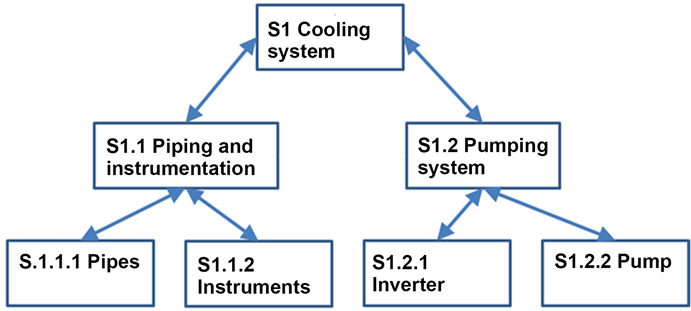
Figure 3. Product breakdown of an example system.
The goal of a design team is to bridge the gap between needs and technical solutions as fast as possible and with costs as low as possible. This is a case of flow system according with constructal theory, which says “for a flow system to persist in time, its configuration must morph such that it provides easier access to its streams” [9] . Adoption of definitions which help engineering work is a way to give easier access to the information flows.
Given the assumptions, this work postulates in development section some definitions along their justification and discusses the limitations of such concepts in discussion section.
3. Development
The following paragraphs postulate some definitions and along them, this work gives some explanation of why such definitions are important. This work proposes the following concepts:
Function status;
Function relevance;
System status;
System phase;
System functional equivalence;
Product operating mode;
Product procedure;
Product operating mode reliability;
Product operating mode availability;
Product operating mode observability;
Product procedure controllability;
Product operating mode risk;
Nominal (qualifier for operating modes);
Degraded (qualifier for operating modes);
Downgraded (qualifier for operating modes);
Forbidden (qualifier for operating modes).
Function status is the current situation of a given function and assumes a single value from a predefined list, as shown by Equation (1).
(1)
For instance, it may be “active” when the action is occurring and inactive when the action is neither happening nor have a fixed delay to start. Typically, functions may also be in “standby” if the action needs to be ready to start within a predefined delay and locked if that action must not start to avoid accidents. The function status also may reflect some discrete levels of available performance, like “active―100%” or “active―50%”. A set of sensor readings normally estimates the status of a function. Noise and imperfections degrades the precision and reliability of such estimation, as seen in Figure 1. For instance, the status estimation of an electrical supply function may use tension and current readings at circuit breaker. Function status is the base to the definition of system status.
Function relevance―Equation (2): Service and Received functions are relevant for system status construction if they change their status during system operation and at least one of the following conditions is true:
First, the marginal cost the function introduces in equipment sizing is significative.
Second, expected costs due accidents caused by this function inadvertent actuation during system life is significative.
(2)
where “Change” is 0 when the function does not change its status (like a physical support) and 1 when it changes its status (like a power supply function). Sizing impact and risk are real numbers expressing the monetary costs.
Functions that do not change status, like physical support, are not relevant for system behavior. For instance, doors functions (to block passage) typically have little importance inside homes, but when there are security or safety concerns, control systems often watch their statuses. In short, relevance is the global monetary impact (acquisition costs and lifecycle risks) of adding a service function to a system. This concept is useful to simplify with objective criteria the behavior model of a system, keeping risks and cost under control during specification and design. For each project, managers must define which is significative in terms of monetary impact. Setting a higher threshold means tolerating more risk.
System status: given a system giving N functions and receiving M functions, a given system status is a unique combination of statuses of the N + M functions, as shown at Figure 4 and Equation (3).
(3)
where s is the system status, S is the set of all desired statuses for the system, the subscript k stands for a single given status within the set of statuses of each function. In other words, a system status value is a mode of interaction with other systems at interface (the rest of the world in Wymorian system definition). This concept is fundamental because both design and operation of systems depends of a shared definition of the system interactions with the rest of the world.

Figure 4. Illustration of some states of a system.
Interactions involve both received and service functions. Mistaking (or forgetting) such aspects may lead to integration problems and system rework.
The word “status” was adopted instead of word “state” to make the difference between earlier concepts named by the word “state”, specially the vector of variables representing system conditions.
In practice, a single variable stands for the system status, which may assume a finite (desirably small) number of integer values associated to a name. To reduce effort, specifications must avoid the inclusion of unnecessary system status, selecting only useful ones. In Figure 4, assuming each function has 3 statuses, it is possible for the system to have 34 = 81 different status, but only one function is relevant. This concept is fundamental to model system behavior, being an objective definition for a basic element of state machine diagram. The objectivity allows having rigorously the same description for a given system, regardless of the person in charge of writing, gave the person has full knowledge of system functions. Such uniformity eases specification and design activities linked to definition of system behavior and analysis. Status concept is also useful to organize the definition of functional, non-functional, performance and test requirements, reducing project risks. This definition of status is a black box definition as it is based on functions at interfaces only.
System phase is a system event of changing, in a finite time, from a given status A to another status B.
This definition involving time is important because unlike software where state transitions are virtually immediate, physical systems need considerable time to change their statuses. As status, phase is a fundamental element in behavior modeling and its objective definition helps engineering activities. Status changes are events of a given system which need internal actuators (or actuators from systems in interfaces). Last, but not least, phases are source of integration problems in later design or construction steps because designers tend not to define phases during early design. Typical problems are inadequate response times, lack of actuators, forgotten external services or even lack of a required phase. Like for status, system specification must reduce the number of phases to the least necessary to meet system goals, as every phase needs more design effort and equipment.
Given the system status and system phases definitions, it is crucial to postulate the system functional equivalence property, as follows.
System A is functionally equivalent to system B if and only if A receives and gives at least the same functions, have at least the same statuses and at least the same phases as system B.
This property is not commutative, that is, a system with more statuses may be equivalent to a simpler system, but the opposite is not true. Figure 5 presents an example of two systems having the same statuses, where the system on the right is equivalent to the system on the left, but the opposite is not true. In Figure 5, each status (A, B and C) must first be equivalent in both systems, that is, have the same status for every function (received or service). This concept is important because a given system may replace any equivalent system. In fact, a system specification should give a complete constraint to declare if a proposed solution is functionally equivalent to the needs. This definition is important to have in mind when writing a specification and when selecting alternate solutions for a given specification. A specification that does not define the required system statuses and phases for the solution is incomplete and may incur in two risks. The first risk is the designer does not include required statuses and phases, which will lead to integration problems and costly rework after construction. The second risk is the designer takes an over conservative approach and gives unneeded statuses and phases, adding too many actuators and design effort, which makes the system more expensive.
Product operating mode is a region in the space-state of the internal variables of a given product that satisfies a given status of the corresponding system, as shown in Equation (4).
(4)
where is the vector of measured state variables of the product under study and M is a sub region of the full space-state X where the system under study achieves a desired status. This means that every product mode of operation is a technical response to at least one system status. The internal variables of a product form a vector including parts modes of operation and other variables provided by sensors or software functions. While modes and status seem similar, they are quite different, as functions (abstract, non-material entities) are the base of status concept and physical measures are the base of modes. The importance of such definition lives in the formal separation between needs (specification) and solution (design). Further, modes are also a foundation for a series of concepts useful for design and analysis.
Product procedure is the list of events (on parts or adjacent products) necessary to change from operating mode D to operating mode E in a given finite time.
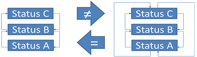
Figure 5. Example of equivalent and non-equivalent systems from functional point of view.
While phases are behavior changes in imaginary and abstract entities (system status), product procedures are sets of:
1) calls on parts procedures (physical actions of actuators);
2) parts operating modes or other variables readings;
3) procedure decisions (example: to abort the procedure if any part does not change its mode); and
4) event waiting times (example: the procedure waits a part change its operating mode).
While phases have only information of the system behavior as a black box, product procedures have also information on events inside the product. Typically, actuators (for instance, motors, pistons, relays) along received functions (for instance electricity, fluid flows) perform actions contributing to implementation of phases of a system. Every product procedure must solve the problem of realizing at least one system phase, and every system phase must have as solution at least one procedure. Product procedures must include detailed description of events on its parts and on adjacent products. The concept of product procedure is fundamental for managing risk during product design, as procedures may cause accidents (project risks). Project risks arise from lack of workable procedures to achieve mode changes, typically due forgotten actuators. Accident risks arise from the possibility of unforeseen procedures that result in foreseeable accidents. When neither technical solutions nor operation advices in product manual prevent dangerous operation, the product may pass acceptance tests but may cause damage later.
Product mode reliability is the probability a given product can reach (within a time delay) and keep a certain operational mode for a pre-defined time assuming all received functions are in nominal conditions, as shown in Equation (5).
(5)
where t is time, T is the given delay, s is the desired system status. It means that all service functions related to the operational mode are working. Some authors define reliability as the probability that a single function achieves its performances for a given time. Other authors define reliability as the probability of meeting all functions performances for a given time.
For this work, this definition is important because not all functions may be necessary, and two or more functions may be necessary at the same time. Furthermore, reliabilities may change from one mode to another. The typical approach of adopting a single reliability number to a product is valid only when it has a single relevant operating mode, which is the case of many simple parts. The assumption of nominal conditions of all received functions is important because typically the product designer has no authority or possibility to change received functions properties. Another reason is that it is necessary to know the individual contribution of each part to the upper level product failure rate. Last, but not least, the client does not want only the reliability of the product when it is on the operating mode, but also the reliability of the procedure of entering in operation. Clients want to know the probability the product performs a given mission on demand, which implies the capability of the product to start and work for a given time.
Product mode availability is the probability a product, in a moment of its operating life, reaches (within a time delay) and keeps a certain operating mode, given all needed received functions work, as shown in Equation (6).
(6)
The reasons for this definition are like for the reliability definition. The available time excludes planned and unplanned maintenance operations.
For design and operation an important concept is product mode observability.
Product operating mode observability is the probability, within a given period, the design instrumentation and signal processing estimate the product is in operating mode A when the product is really in mode A.
This concept is fundamental to define product instrumentation during design and risk analysis, as mode estimation errors affect safety of people, equipment and environment.
It is important to note that each system status must be unique to allow product mode observability. To create a new status to a system, at least one function needs to have a different status. This uniqueness property is also important to reduce the number of statuses of a system and so, the engineering effort. Besides, allowing the same status to receive many names, many positions in a state machine diagram would create confusion in communication and problems in product mode determination. Such issues even affect safety. Note that not all modes are equal in terms of safety, and this definition allows having different observabilities for each mode, increasing the observability when it is critical. This is the case for accident or modes that potentially cause accidents, that need better instrumentation than inoffensive modes.
Product procedure controllability is the probability a procedure completes within expected delay and without causing risks or damage, assuming all received functions work perfectly.
Any procedure may need a complex sequence of activation of technical functions or received functions, and the order of such activations may affect product safety. Besides, the control system needs to keep the operating mode estimation while the procedure runs, keeping track of executed steps and next steps. Finally, product design must manage risks during procedures because larger (than in steady operation within an operation mode) risks may appear while a procedure is running. One example is a sea water circuit which needs to replace sea water with fresh water when the pumps are inactive, as sea water is corrosive when stationary. The period between pump stop and end of refilling with fresh water is riskier than normal operation because any interruption may leave sea water in the circuit, leading to corrosion.
Product operating mode risks are risks that arise specifically from a given operating mode.
A product may have hazards (potential failures and accidents) and risks (expected financial damage due a given hazard). There are three main sources of risks, amongst others.
First, risks that a part suffers an intervention (human, equipment failure, external aggression, fires) that generates a dangerous condition.
Second, the risk that the control system (human operators or computers alike) does not estimate correctly the current mode and allows further aggravation of a disfunction. It may be lack of start of a safety procedure.
Third, risks that the control system starts an inadequate procedure, causing or aggravating accidents as some part modes are important for safety at the level of the upper level product.
Sometimes hazards come from materials composing the product and are present in all modes, so related risks are not working mode risks. But there are many risks arising from incorrect behavior and risk analysis must cover all modes, which also improve the probability that the analysis covers all sources of risks.
A set of key concepts for design are nominal, degraded, downgraded and forbidden qualifiers for operating modes.
In nominal operating modes, the product realizes foreseen functions of the related status following all performance requirements and without unnecessary risks.
Nominal modes are ideal conditions that product design foresaw for operation and such modes are narrow regions within the space-state.
In degraded operating modes, the product gives foreseen functions of the related status, but either its physical configuration generates unnecessary risks, or some performances do not meet specification.
An example could be a ship sea water cooling circuit after stopping all pumps and before isolating the network and removing the sea water (stagnant sea water is corrosive and could cause a flooding). Degraded status means the operator needs to do something to reduce risks in a normal pace (it is a yellow flag or a warning).
In downgraded operating modes, the product gives foreseen functions of the related status without unnecessary risks, but it does not meet all performance requirements.
Such modes are interesting for graceful degradation, which means the product has smaller reliability at nominal performances than for lower performance levels. This way, product design may achieve an interesting compromise between cost and safety in cases in which the sudden function interruption may cause large damages.
An example could be an electrical network of an all-electric ship with many non-redundant power sources. If one power source is down, top speed is little reduced, but the probability of losing all power sources in a single voyage is very small if compared to a single engine design. Completely losing propulsion power may cause accidents, like ship sinking, environmental disasters and payload loss.
Forbidden operating modes are regions of the space-state the product must not enter or exit as soon as possible after entering it.
An example is a nuclear reactor with residual heat and without coolant in the reactor pressure vessel, situation that operators must prevent and may occur after a large rupture in reactor coolant pressure barrier. Forbidden modes mean operators and control system must act at once to prevent a greater damage (it is a red flag for operators).
Such definitions (nominal, degraded, downgraded, forbidden) are important to define procedures, as it is desirable that the control system estimates without interruption the product operating mode while a procedure is running. That means that, during the procedure between two nominal modes, the product should stay in degraded modes. This way, the control system allows operators to understand the situation and reminds that the procedure still has more actions. Additionally, designers must not absolutely foresee a procedure passing by a forbidden mode and must communicate throughout the project what are the forbidden modes. While system status depends only on external interactions, the nominal, degraded, downgraded and forbidden mode qualifiers need product internal information (operating modes). In general, nominal modes have narrower regions in space-state than downgraded and degraded statuses, as shown in Figure 6.
As final remark of this chapter, the proposed concepts respect the formal segregation between system goals and technical solutions. System concepts are related to customer goals and used during specification activity and product concepts are related to solutions (applicable to design activity). Such formal segregation is a reality as organizations that produce specifications (integrators) are different from those that design solutions (part suppliers) in response to specifications. If language concepts impose such segregation (specifications become forbidden to mention concepts of the solution domain), integrators personnel concentrate their attention in system goals. This clear responsibility and role distinction tend to produce better specifications, to reduce conflicts, to reduce the risk feeling, to reduce rework, to reduce project delays and costs. Beyond the clear role definition, the system status concepts help people in charge of specification to understand and express the behavior needed. The very novelty of this work is the skill to be able to model system behavior (as a black box) before design while keeping behavior description concise (avoiding state explosion). Such skill significantly improves information flow in a project, reducing lack of needed information for design and giving the basis to prevent unneeded features in design.
4. Results and Discussion
This section shows an example of simple system, purposely neglecting many aspects, but showing some proposed definitions in practice. Figure 7 presents the block diagram of the system along with related functions. SF stands for service

Figure 6. Representation of mapping of mode qualifiers in space state.
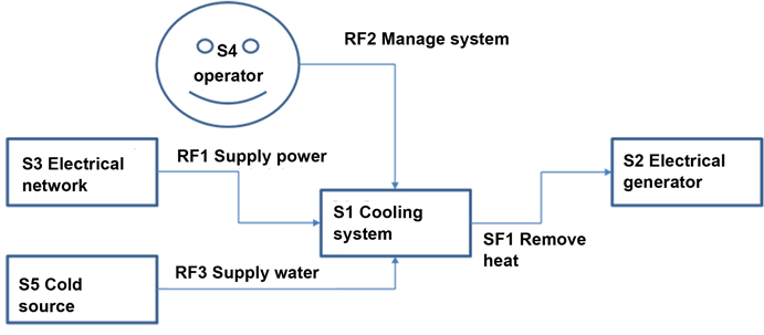
Figure 7. Block diagram of example system―a cooling system.
function meaning that it is a function provided by the internal part of the system under study. RF stand for received function which is a function the system under study receives from external part of the system. Note that this work considers the operator is a system giving services to the system under study, as it would not be possible for the cooling system to work without the decision making of the operator.
Table 1 shows the list of function statuses for each function related to the system under study. Note that there are more received functions than service functions and that the estimation of the SF1 Remove heat function status involves many sensors and operations. It needs flow measures in both sides of heat exchanger, detection of circuit breaker position, threshold detection and logic operations.
Table 2 presents the definition of each of the system statuses of this example.
Let us assume Figure 8 presents the physical diagram of this system excluding the electrical part. As the circuit breakers, pumps and the valves conditions are the only measured variables, there are only 6 variables in the vector characterizing the system state.
Let us assume each of those variables are binary as Table 3 presents the statuses for each technical function, whose short name is TF. Technical functions

Table 1. List of functions statuses.
Table 2. List of system statuses.
Table 3. List of technical functions statuses.
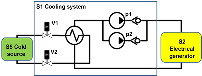
Figure 8. Physical diagram of example system.
are functions internal to the system which give contribution to realization of a service function and the estimated operating mode of the parts compose the state vector. Let us assume that it is enough both valves are open to have flow in the cold source circuit (cold source imposes differential pressure all time). Other assumption is that if one pump is running, the cooling fluid flows into the electrical generator. The last assumption is the parts operating modes are the same as their respective technical functions statuses.
Once Table 3 defined the values for technical functions status, it is possible to represent the full space-state, for example, in a Carnot Map if all variables are binary. Figure 9 presents the space-state of this example product along some allowed procedures. It is worthy to remind that procedures must avoid the forbidden regions and that operation should limit the time the product stay in degraded modes. In this example, when two pumps run simultaneously, it is a degraded mode because pumps both run far from their design point. The nominal standby mode occurs only when both pumps receive electrical tension from circuit breakers and both valves are open. If there is at least one pump receiving electrical tension, the product is already in standby mode, as it may theoretically start within 20 seconds. However, if there is any valve closed, the product is in a degraded mode because there is risk of starting a pump without cold source. Design should forbid starting without cold source because it would cause overheat in the network due the work injected by the pump, potentially damaging equipment. If there is any circuit breaker open, this degrades the operating mode because it has smaller reliability than in nominal conditions, yet the system still reaches operating status.
Beyond the studied configurations, there are also many states ignored because they are physically impossible or at least improbable. In this example, it is impossible for the pump to run if the respective circuit breaker is open, so every state where it happens is an unknown or unforeseen situation.
It is interesting to report a project which adopted part of the proposed concepts with successful results: “Status Approach” (translation of “Approche par

Figure 9. Presentation of the space-state in form of Carnot Map.
Etats” from French) of EDF (Electricité de France). “Status Approach” is a set of procedures for incidents and accidents management at disposal of operators in charge of safety of the EDF nuclear power plants. This method replaces the old management way called “event-based” (translation of “approche événementielle”) which was adequate only to accidents whose typology allowed an exact diagnosis from the start. The event-based management had about 30 procedures, some linked to starting events and others related to combination of events, which caused a kind of explosion of procedures. The “Status Approach” changed the focus from the accident causes to the current plant status, setting simple goals and priorities for operators [10] . The “Status Approach” needed the implementation of a new instrumentation called “the ebulliometer”, which allows to estimate the status of core cooling function (attaining a high level of operating mode observability) [10] . With this information, operators know the adequate procedures to control the situation avoiding the core fusion regardless of the combination of initiating events. Those modifications reduced accidental procedures to 6 and reduced risks due human factors. Additionally, the “Status Approach” reduced risk of human error in accident diagnosis like 3 Miles Island accident [11] , improving overall safety. The “Approche par Etats” from EDF is an example of how much cost reduction (software, training and project risks) the application of system status concept may reach [12] . However, “Status Approach” was not a full design, but partial modernization which did not touch major parts. It means a full application in all design phases has yet unexplored potential to reduce costs and risks.
Such definitions are compatible with any system engineering method, be it model-based or document based. As definitions are state of mind entities, it is enough the entire design team adopts them to obtain positive results. It is important to remind that design should impose all parts inform their operating mode to the upper level product and such data must be the input to calculate the operating mode of the product. Conversely, product design should give setpoints to parts and product design should call parts procedures when making the product’s procedures.
It may seem that all information is in control system and that all information of every hierarchy level is part of the same system, the control system. This vision in fact ignores systems approach and does not model information interfaces between hierarchy levels. System engineers should keep in mind that a control function (monitoring, command or even closed loop control) is a service function of the control system. The control system realizes functions for systems in every hierarchy level, but functions must document every information exchange between adjacent hierarchy levels to keep operating mode observability. For instance, the activation of a given closed loop control necessarily changes the status of the system receiving this service. If system engineering does not declare explicitly in terms of functions the information the upper level system receives (or any functional exchange), subsystem status identification is impossible. This way, this work advocates the use concept of visibility from object orientation, defining that every information is private by default and system functions take care of all information exchange. Doing otherwise prevents the application of status concept because functions stays implicit (undeclared). Without imposing the private visibility for every variable, design of an upper level product may access every variable in parts without declaring functions to make such accesses. This way, the need of accessing an internal information of a part (to use in upper level operating mode estimation, for example) stays undeclared, and if undeclared, they cannot be in the status definition table. Concluding, a weakness of the proposed concepts is without explicit system functions declaration, which may be common within control systems, system status cannot be known. Specially in document-based engineering methods, system functions declaration may be tricky to enforce.
An indirect consequence of this weakness is the need of rigorous observance of hierarchy, preventing information flows between systems that are not in the same or adjacent hierarchy level, as shown in Figure 10.
In specification activities, if the system S1 gives a direct procedure call to S1.2.2, it is in fact an undeclared function of S1.2 system (because S1.2 by composition includes S1.2.2 system). Such lack of function declaration violates the basic rules of private visibility and function declaration, disabling the very possibility of system status definition. Furthermore, such direct access may cause dangerous behavior within S1.2 once such call does not consider the whole of the internal variables of the S1.2 system.
In design activities, if design uses the operating mode of S1.2.2 in S1 state vector, then design increases complexity of S1, risking state explosion. Further, it is not necessary as S1.2 should realize correct synthesis from S1.2.1 and S1.2.2. In fact, if this need exists in S1, it means that S1.2 design has an error.
The proposed definition of system status is complete because it includes all functional interactions of a system in both senses. Of course, it ignores completely internal variables and it is a synthesis and not a complete set of information if considered in a specific product decomposition (hierarchy) level. However, the process variables of a product (compose the state vector) are necessarily
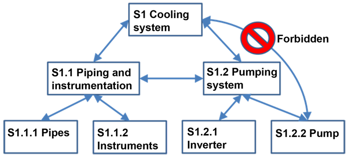
Figure 10. Illustration of forbidden functional exchange.
related to the functions of its subsystems, otherwise they should not exist. Furthermore, according with adopted system definition, if a given information goes out of a subsystem to the upper level system, there is a corresponding output related to a function provided by the subsystem. That means the state vector of any product is composed by information provided by parts as part of their functions, and by system definition, it cannot be otherwise. Therefore, to achieve completeness in behavior modelling, system engineering activities (specification, design, analysis) need to check statuses and phases recursively at every hierarchy level. This means that the need of uniformity at all product decomposition levels is another limitation of the proposed concepts. The use proposed concepts in a single system level does give insights, but an organization may only obtain full profit if engineering activities apply those concepts uniformly in all product decomposition levels.
On the other hand, this definition is the simplest possible, as it considers only external interactions, ignoring internal details, contributing to the onion model approach [8] . So, the proposed concept of system status reduces the state explosion problem and eases system level engineering activities completion before entering subsystem activities. The concept of function relevance also contributes to further mitigate state explosion, allowing design neglect functions without incurring in unmanaged design risks. Therefore, despite its reductionism, the proposed status definition allows complete behavior modelling when applied recursively at all hierarchy levels. This means the strongest points of this work are simplicity, ease to understand and recursive (hierarchical) nature. According with Constructal Law [9] , improving the flows (in this case, easing engineering activities) is a condition for success for any flow system, human organizations included.
Internal complexity has not limits as each part in the hierarchy makes a synthesis of its operating mode in a single variable, easing management. Hierarchy is a natural phenomenon according with Constructal Law [9] and is currently in use in system engineering methods, for instance in product breakdown. So, to ease information management (and systems management), each part should synthetize the vector of state variables into a single variable (operating mode) and pass it to the upper level product.
Those definitions help hierarchical control architectures, as they define synthetic information exchanges between hierarchical levels. Subsystems should have a function to report their statuses to upper level system and the upper level system calls available phases on the subsystems. This way, with minimal information exchange, complex systems may work in closed loop at every level, characterizing a cyber system where orders are in terms of goals, like in state analysis [5] .
The use of proposed concepts should keep in mind the goal of mitigating project risks due incomplete specification, like accidents, production of solutions that do not meet requirements, low reliability, delays, rework and cost overruns. Other family of issues are inefficiencies associated with product oversize, like excessive capabilities, unneeded actuators or reconfiguration capabilities.
If an engineering work (specification, design, reliability assessment or risk analysis) consider all ways of interaction (system statuses) with the other surrounding systems and their changes (system phases), this completeness reduces projects risks. One may prove this by absurd: if a specification does not declare this information explicitly, there are blank cells in the table equivalent to Table 2. It is impossible to know a priori if such omissions present risk or not (unless the system behavior is trivial, having only two statuses: on and off), and the number of unmanaged risks increases more than linearly with the number of systems working together. This is due to the explosion of the number of interfaces and the lack of communication about the simultaneous combination of functions in time. Whenever engineers perceive their ignorance about this subject, they simply tend to prepare for the worst case, giving any combination, adding unneeded configuration capabilities. Or, as experience shows, builders find many integration problems during integration, like lack of actuators or need of new ways of operation.
If a system engineering work consider only the foreseen statuses and phases, this conciseness rationalize work and prevent further studies or equipment with low probability of employment. In this spirit of conciseness, if a function is not relevant in each system status as section 3 defines, the specification should ignore it, so one could add another possibility of function status in the status definition table (like Table 3): “irrelevant”.
In the activity of preparing specifications for a system and their subsystems (like Figure 7), the use of the proposed concepts helps to clarify and communicate system behavior and analysis. The utility of those concepts may improve if the specification meets the following requirements. First, whenever one function is active in a status (in system status definition table, like Table 2), the specification should define at least one performance requirement linked to that status and function. Then, the specification needs to refine each performance requirement with reliability and reparability requirements. Second, if a function is in standby in a status, beyond the same requirements for active functions, the specification need to add largest probability of failure on demand and the time response. Third, for functions in forbidden status, the specification needs to define the acceptable frequency of inadvertent actuation. Such requirements have significant cost impacts and the specification should consider them in an exhaustive way to avoid product rework (and cost overrun) in later engineering phases.
Comparing the proposed concepts to those in with state analysis [5] , system status relates to a region in space-state (operating mode) where the system state may be (“state” word here has the meaning of adopted in state analysis). So, the proposed concepts harmonize completely with state analysis and add the proposition to add system level information synthesis to support decision making in an integrated way. Also, the proposition to formally match models to system boundaries may improve work flow.
Comparing to [2] , the proposed concepts are quite simpler, as status and modes apply to every level of specification and design in the product breakdown. [2] adopts many different concepts, like use case, mode of operation, sub mode of operation, state and physical configuration depending on context and system hierarchy level. A comparison with the state concept from [2] reveals the proposed definitions seem more complete because it considers both system goals (system service functions) and system dependencies (received functions). For [2] , state definition is related to system goals and a set of physical configurations but makes no explicit mention to every interaction at system boundaries.
Because in a complex system the reliability requirements are not uniform, varying according with risk levels, design should group subsystems with similar requirements. The reason is subsystems typically have mutual dependencies, so a less reliable subsystem would impair functions of more reliable subsystems. On the other hand, reliable subsystems are more expensive to design, build and keep, so design should reduce their number. If they entwine with many subsystems, the number of reliable subsystems must grow. On the other hand, high reliability equipment should be in standby in normal operating modes, working only in emergency. The reason is normal operation causes wear and tear of any part, regardless its control quality during design and fabrication. Therefore, standby operation has the potential to improve reliability of safety-related equipment and reduce costs of replacement of equipment used in normal operation. In short, by segregating and keeping high reliability functions in standby, design may reduce costs and maximize safety.
Another limitation of the proposed concepts is that taking them into consideration do not assure design feasibility, so specifications should compensate this risk associating flexibility to requirements. This way, there is room for designers and equipment suppliers to know what is negotiable and what is not. Additionally, a requirement flexibility should be inversely proportional to the probability of the respective requirement being possible. This means if it is sure that the requirement is workable, its flexibility may be non-negotiable, but if there is no feasibility proof a priori, the flexibility should be at least negotiable.
This work ignores non-functional aspects like environmental conditions, and, for instance, time of permanence in each status is relevant to size products. However, it may be interesting to define non-functional requirements in function of product operating modes, as it happens for electronic parts, that have temperatures for operation and for storage.
The specification of a system must define the list of phases to be available for the client, but the detailed design of product procedures is a part of product design and must not be in the specification. A factor that dictates the use of the proposed concepts is that details of product procedures hide project risks as they may need more parts or more functions from external systems. To prevent such risks in later design stages, in conceptual studies, design should define nominal, degraded and forbidden statuses before defining product procedures. Additionally, before the end of conceptual studies, design should prove that every procedure works within allowed (nominal or degraded) operating modes.
It is interesting to emphasize that those concepts respect a formal division between goals and technical solutions, being the system concepts associated with customer goals (goals domain). The product concepts are associated with suppliers work and existing technical solutions (technical solutions domain). Figure 11 shows the main proposed concepts with their relations across domains (goals or solutions), being the vertical line the formal segregation between those concepts.
This work novelty is the creation of concepts to support functional behavior modelling still in specification, where changes are easy and cheap, as shown in Figure 12.
5. Conclusions
The central idea was to standardize the vocabulary for engineering activities; adopt definitions assuring completeness and reduce overall effort. The proposed concepts aim at simplicity, intuitiveness and efficiency, giving a standard packet of information between systems (and products) of different hierarchical levels.
This work proposed a set of system engineering concepts and analyzed qualitatively the advantage of the use of such concepts.
While this work does not reach a complete method, it gives guidance for improvement of any method in practice (model based, or document based). It analyzed some consequences of proposed definitions and discussed limitations of the concepts.

Figure 11. Summary of proposed concepts.

Figure 12. Present work innovation.
During specification, it is typically possible to define system behavior as a black box because people in charge know how the external environment should be. However, people in charge of design know the typical behavior of comparable products, but they do not know the specific behavior of the system under study unless explicitly informed. So, as current approaches tend to limit specification just to functions (system goals) and constraints to inconvenient features (system constraints), innovation becomes dangerous or expensive.
In short, this work showed that defining system status as a way of interaction with other systems at interface (black box behavior modelling), there are four important consequences. First, specifications need to define requirements by status and include the list of phases. Second, design needs to study each status and take phases into account, defining all needed operating modes and procedures. Third, reliability and availability analysis needs to make assessments for each operating mode and procedure. Fourth, risk analysis needs to consider each operating mode and every step of procedures.
Therefore, the key contribution of this work was the creation of system engineering concepts (function status, system status, system phases among others) that support system behavior specification; they help to reduce overall design effort and project risks.
Future works involve applying the proposed system status concept to a project and develop a design methodology.
Conflicts of Interest
The authors declare no conflicts of interest regarding the publication of this paper.
Cite this paper
Freire, L.O., de Andrade, D.D.A. and Monterrain, D. (2018) A System Status Definition to Improve Behavior Description in Specifications Based on Constructal Law. Open Journal of Applied Sciences, 8, 315-337. https://doi.org/10.4236/ojapps.2018.88024
References
- 1. Ogata, K. (2010) Modern Control Engineering. 5th Edition, Pearson, Upper Saddle River.
- 2. Wasson, C.S. (2006) System Analysis, Design, and Development: Concepts, Principles, and Practices. 1st Edition, John Wiley & Sons, Inc., Hoboken, 832 p.
- 3. IEEE (1990) IEEE Standard Glossary of Software Engineering Terminology. Institute of Electrical and Electronics Engineers—C/S2ESC—Software & Systems Engineering Standards Committee. IEEE Std 610.12-1990.
- 4. Wymore, A.W. (1993) Model-Based Systems Engineering. 1st Edition, CRC Press, Boca Raton.
- 5. Ingham, M.D., et al. (2006) Generating Requirements for Complex Embedded Systems Using State Analysis. Acta Astronautica, 58, 648-661. https://doi.org/10.1016/j.actaastro.2006.01.005
- 6. Weilkiens, T. (2006) Systems Engineering with SysML/UML—Modeling, Analysis, Design. 1st Edition, Morgan Kaufmann OMG Press, Heidelberg.
- 7. Lykins, H., Friedenthal, S. and Meilich, A. (2000) Adapting UML for an Object-Oriented Systems Engineering Method. Proceedings of the INCOSE International Symposium, 15-20 July 2000, 490-497.
- 8. Childers, S.R. and Long, J.E. (1994) A Concurrent Methodology for the System Engineering Design Process. INCOSE International Symposium, August 1994, 226-231. http://onlinelibrary.wiley.com/doi/10.1002/j.2334-5837.1994.tb01709.x/abstract
- 9. Bejan, A. and Lorente, S. (2013) Constructal Law of Design and Evolution: Physics, Biology, Technology, and Society. Journal of Applied Physics, 113, Article ID: 151301. http://dx.doi.org/10.1063/1.4798429
- 10. Bataille, M.C., Sido, M.B. and Birraux, M.C. (2011) Rapport de la Mission Parlementaire Sur la Sécurité Nucléaire, la Place de la Filière et Son Avenir. Assemblée Nationale, Paris, 565.
- 11. Kemmeny, J.G. (1979) The Need for Change: The Legacy of TMI. The President’s Commission on the Accident at TMI, Washington DC, 179.
- 12. Tarride, B. (2013) Physique, Fonctionnement et Sûreté des REP. 1st Edition, EDP Sciences.