Open Journal of Applied Sciences
Vol.04 No.13(2014), Article ID:52407,9 pages
10.4236/ojapps.2014.413051
Bi-Directional Excitation of Radio Frequency Waves Using a Helical Antenna in Non-Uniform Plasmas towards a Compact Magnetoplasma Thruster*
Yasuyoshi Yasaka, Yoshifumi Hayashi, Hiromasa Takeno, Satoshi Nakamoto
Department of Electrical and Electronic Engineering, Kobe University, Kobe, Japan
Email: yasaka@eedept.kobe-u.ac.jp
Copyright © 2014 by authors and Scientific Research Publishing Inc.
This work is licensed under the Creative Commons Attribution International License (CC BY).
http://creativecommons.org/licenses/by/4.0/


Received 23 October 2014; revised 28 November 2014; accepted 15 December 2014
ABSTRACT
Magnetoplasma thruster is one of the attractive plasma engines for space propulsion in future manned deep space exploration. Usually two helical antennas are equipped to produce and heat plasmas with separate radio frequency sources. It is presented in this paper that a helical antenna, which is used to launch one wave mode in one direction so far, exhibits bi-directional nature, where the waves with different mode numbers are launched and couple with electrons and ions selectively in opposite directions. A two-dimensional numerical calculation is performed to predict wave propagation and power absorption in a non-uniform hydrogen plasma immersed in a non-uniform external static magnetic field, based on the hot plasma theory. It is confirmed that appropriate choice of the excitation condition of the antenna can select axial propagation direction of specific wave modes and consequently select a species that absorbs power from generated waves. A small-scale experiment is performed to confirm the prediction of the calculation. By measuring a change in electron and ion temperatures due to the wave launch from the helical antenna, it is found that both the production and heating at different axial positions are accomplished simultaneously by one antenna showing that another type of the radio frequency driven magnetoplasma thruster would be achieved.
Keywords:
Plasma Thruster, Magnetoplasma, Radio Frequency, Helical Antenna, Plasma Waves

1. Introduction
Radio frequency (RF) driven magnetoplasma thruster is one of the electric propulsion systems, in which high density plasmas, produced by helicon waves (HW) launched from one RF system at a frequency ω such that  with Ωi being the local ion cyclotron frequency, flow downward to the ion cyclotron range of frequencies (ICRF) heating section where the other RF system is used to excite ion cyclotron waves (ICW) at
 . The ICRF waves resonantly interact with ions and accelerate them in the direction perpendicular to the external magnetic field. A magnetic nozzle, which is a region where the magnetic field diverges, converts the perpendicular velocity of ions into the parallel velocity to create a thrust [2] [3] . The amounts of the thrust or the velocity of exhaust plasmas can be varied by controlling the RF powers in the two RF systems relatively or independently.
RF-driven magnetoplasma thrusters often employ helical antennas as launchers of HW and/or ICW, probably due to the fact that they can generate right- or left-rotating RF fields with respect to the static magnetic field selectively by choosing the helicity of the antenna [4] . It is well known that the right-rotating RF field preferably couples to HW and the left-rotating one to ICW [5] [6] . In doing so, it is the field component of one axial direction that is used as the source of HW or ICW [3] .
The helical antenna may, however, be capable of launching RF fields in positive and negative axial directions simultaneously. Furthermore, it is expected that when the helical antenna launches the right-rotating RF field in the positive axial direction, the left-rotating RF field is launched in the negative axial direction and vice versa. This bi-directional simultaneous launching of different fields is attractive for simplifying the RF systems toward a compact magnetoplasma thruster.
The above discussion about HW or ICW excitation by the rotating RF field is based on the cold plasma theory in a uniform medium. Usually in such thrusters the static magnetic field is non-uniform as well as the plasma density, and consequently, the theory of plasma waves in uniform configuration cannot be applicable for calculating wave fields and power absorption profiles. Arefiev et al. [7] showed a calculation of wave fields in cold plasma of one-dimensional non-uniformity including nonlinear effects. Prediction of wave fields and power absorption in a realistic configuration of a device requires at least two-dimensional calculation on the basis of the hot plasma theory in non-uniform medium.
In this paper we present a two-dimensional calculation of wave propagation and power absorption in a non- uniform plasma immersed in non-uniform static magnetic field [8] based on the linear hot plasma theory. Bi- directional property of the helical antenna is investigated numerically by using a simple model antenna that approximates the helical antenna. An experimental device is constructed, in which a helical antenna and some diagnostics are located in a diverging magnetic field. We present the experimental evidence of bi-directional characteristics of the helical antenna that the RF fields of different kinds are launched in opposite directions through the measurements of plasma production and ion heating. As a result both the production and heating are accomplished simultaneously by one antenna showing that another type of the radio frequency driven magnetoplasma thruster would be achieved.
2. Calculation of Wave Fields
2.1. Helical Antenna
Helical antennas are commonly used to launch waves in ICRF. One example of the helical antennas is shown in Figure 1, where two rings on both sides are connected by two helical straps displaced by 180 degrees with respect to each other.

Figure 1. Configuration of the helical antenna and expected wave fields.
A pair of terminal points is located at the center of one ring or one strap in order to feed the RF current. The pitch of the strap is in the right hand sense with respect to the external magnetic field B0, and therefore the antenna in Figure 1 is called the right helical antenna. RF electric fields in the cylindrical coordinate  are generally represented as
 , (1)
, (1)
where E0 is the complex amplitude, ω is the wave angular frequency, m is the azimuthal mode number, and k is the axial wave number. It is well known that the right helical antenna excites electric fields given by Equation (1) with m = −1, and the left helical antenna with m = +1 in the direction of B0. Since the m = −1 fields are left-hand polarized (EL), it couples to ICW, of which wave fields rotate in left-hand sense as they propagate in the direction of B0. The m = +1 fields, which are right-hand polarized (ER), are suitable to launch HW in an appropriate frequency range. In VASIMR [2] [3] two helical antennas are equipped: the left helical antenna is used to generate plasmas by HW, and the right helical antenna to heat ions by ICW at the ion cyclotron resonance.
We note that the right helical antenna shown in Figure 1, which excites the m = −1 fields in the direction of B0, excites m = +1 fields simultaneously in the direction opposite to B0. This means bi-directional excitation of the electric fields with different modes from a single helical antenna, and it can be used both to generate the plasma and to heat ions.
2.2. Model for Wave Field Calculation
We calculate propagation, damping and power absorption of waves when the antenna excites m = −1 or +1 fields in a non-uniform plasma. Maxwell equations with a source term representing the antenna current density are solved in an arbitrary non-uniform axisymmetric magnetic field and plasma density in the two-dimensional r-z plane. The wave field E satisfies the equation:
 , (2)
, (2)
where ω is the wave angular frequency, c is the velocity of light, μ0 is the permittivity in vacuum,  is the antenna current density, and
  is the dielectric tensor. For an axisymmetric external magnetic field B0 with
 ,
,  is given by
 (3)
(3)
with

Here, ωpe is the plasma frequency, vi and ve are the thermal velocity of ions and electrons, respectively, and k|| is the parallel wave number determined by the local cold plasma dispersion relation [9] [10] .
Equation (2) is solved numerically in a model device depicted in Figure 2. The device diameter is 100 mm for −400 mm < z < 0, and 350 mm for 0 < z < 550 mm. The applied magnetic field strength on axis is schematically given in the lower part of the figure. It has a peak at some point and decays in both sides. RF waves are
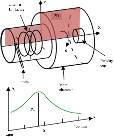
Figure 2. Schematic drawing of the model device and simplified profile of the external magnetic field strength. The antenna consists of three loops displaced by 90 degrees with respect to adjacent one.
launched from an antenna consisting of three axisymmetric current loops L1, L2, and L3 located near z = −200 - −100 mm.
It should be noted that the helical type antenna cannot be directly implemented since the calculation is in two- dimensional. We approximate the current in the helical antenna by plural loop currents with azimuthal phase difference along the axial direction. Approximate positions of a Langmuir probe and a Faraday cup, which are to be used in the following experiments, are illustrated in the device.
2.3. Calculation Results
The current density in the helical antenna is approximated by
 , (4)
, (4)
where Jk, rk, zk, and ϕk are the amplitude of the current, the radial position, the axial position, and the angle of the azimuthal position of the k-th loop of the antenna, respectively [11] , and ω/2p = 1.8 MHz. We represent the helical variation by the discrete step change in the azimuthal angle of each loop, and consider only the azimuthal component of the current. In this expression, when B0 is in the +z direction, m = +1 represents the right-rotating field and m = −1 the left. The summation in m is taken for m = −1 and m = +1, which gives azimuthal variation of Jθ as cosθ (apart from ϕ) that is just the fundamental component of the current in the ring conductors at both ends of the helical antenna and also the helical straps (neglecting axial current) shown in Figure 1. A collection of appropriately phased circular antennas might also be employed in the real magnetoplasma thruster design.
We first use one loop (J1 = 1, r1 = 25 mm, z1 = −130 mm, J2 = J3 = 0) only in order to focus on propagation and damping of fields of a specific azimuthal mode number in non-uniform plasma. The present two-dimen- sional calculation gives profiles of physical quantities in the r-z plane represented by the shaded region in Figure 2 for the plasma composed of electrons, H+ ions, and H2 with the electron-neutral collision frequency ν divided by ω being 0.05. Figure 3 shows the calculation results of (a) the assumed magnetic field strength , (b) the assumed electron density ne of the hydrogen plasma, (c) the left circularly polarized field EL, (d) the right circularly polarized field ER, (e) the power absorption for ions Pion, and (f) the power absorption for electrons Pelec
 (a) (b)
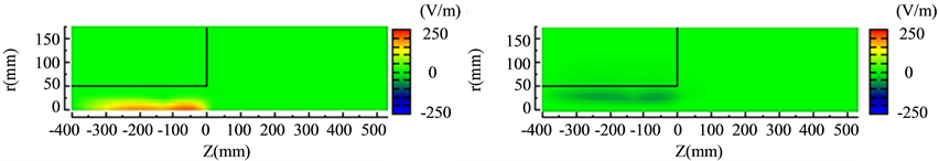 (c) (d)
 (e) (f)
Figure 3. Calculation results of (a) the assumed magnetic field strength |B0|, (b) the assumed electron density ne of the hydrogen plasma, (c) the left circularly polarized field EL, (d) the right circularly polarized field ER, (e) the power absorption for ions Pion, and (f) the power absorption for electrons Pelec in the case of m = −1 mode. (a) ; (b) ne; (c) EL; (d) ER; (e) Pion; (f) Pelec.
in the case of m = −1 mode with the maximum magnetic field strength Bm = 1.5 kG. Here, the electric field amplitude is a complex number and its real part (Re) is plotted. Each frame represents the color contour map in the r-z plane with the legend on the right. The profile of ne follows that of  in the direction parallel to B0 and parabolic profile in the radial direction. For this magnetic field profile, the ion cyclotron resonance is located at z = 10 mm. It is found that EL is large near the axis while ER is small and exists around the plasma edge. RF power is absorbed by ions at the ion cyclotron resonance point as shown in (e), and much smaller power is absorbed by electrons.
It is clearly seen in (c) and (e) that EL extends both sides from the antenna and strongly damped near z ~ 0 at resonance, yielding the power absorption by ions. Since no resonance point exists in the left side of the antenna, the wave field exhibits standing wave profile.
We use three loops of the antenna (z1 = −250, z2 = −200, z3 = −150 mm, and rk = 25 mm), and set ϕ1 = −p/2, ϕ2 = 0, ϕ3 = p/2 to approximate the right helical antenna. In Figure 4 are plotted assumed , Re and Im parts of EL (solid and broken blue lines), Im(ER) (broken green line), Pion (red line), and Pelec (purple line) in the case of (a) B0//+z and (b) B0//−z with the maximum magnetic field strength Bm = 1.3 kG at z = −200 mm. We plot m = −1 component for EL and Pion, and m = +1 component for ER and Pelec, since EL (ER) is the main component of the electric fields of m = −1 (+1) mode. All quantities are of on axis value except Pelec that is at r = 1 cm.
The ion cyclotron resonance is located at the axial position of crossing point of B0 and horizontal dotted line marked as ω/ωci = 1. We see in Figure 4(a) that the amplitude of EL is large on the right side of the antenna (indicated as ANT) and it propagates towards the positive-z direction because the time dependence of EL is EL(t) = Re(EL)cosωt + Im(EL) sinωt. The amplitudes of Re(EL) and Im(EL) are damped at one of the cyclotron resonance points (positive side of the antenna) and, as a consequence, the wave power goes to ions as shown by large increase in Pion at the resonance point of positive side of the antenna. The amplitude of Im(ER) is large at the negative-z side of the antenna. The propagation direction of ER is not clear since the standing wave is formed between the metal walls of both sides. The value of Pelec is slightly larger at the negative-z side than at the positive-z side.

 (a) (b)
Figure 4. On-axis values of assumed |B0|, Re and Im parts of EL (solid and broken blue lines), Im(ER) (broken green line), Pion (red line), and Pelec (purple line, multiplied by 50) in the case of (a) B0//+z and (b) B0//−z.
When the direction of B0 is reversed so that B0//−z, completely opposite phenomena are observed in Figure 4(b); the amplitudes of Re(EL) and Im(EL) are damped at the cyclotron resonance point on the negative-z side, where Pion is particularly large, while the amplitude of Im(ER) is large at the positive-z side of the antenna and Pelec is asymmetrically larger at the positive-z side with respect to the center of the antenna. Figure 4 reveals that the right helical-like excitation of the antenna generates m = −1 mode fields to the positive-z direction and m = −1 mode fields to the negative-z direction in the case of B0//+z, and vice versa in the case of B0//−z. This bi-directionality of selective excitation of the m = −1 and +1 modes leads to controlling the ion heating by EL and the plasma production through electron acceleration by Ez associated with ER.
3. Experiment on Bi-Directional Excitation
3.1. Apparatus
It is found in the previous section that the RF field of m = −1 and +1 mode provides ion and electron heating, respectively. It is usual to use the helical antenna with positive or negative pitch for each mode excitation. We try to launch both the m = −1 and +1 modes from a single helical antenna and perform ion heating and plasma production simultaneously.
The configuration of the experimental apparatus [12] is the same as shown in Figure 2 with the loop antenna replaced by the helical antenna of right helical pitch in the +z direction that is shown in Figure 1. The ion saturation current Iis corresponding to the plasma density is measured by a Langmuir probe (LP) located at z = −320 mm and the parallel ion temperature Ti by a Faraday cup (FC) at z = 260 mm (see Figure 2). The electron temperature Te can be measured by the Langmuir probe and the Faraday cup. The helical antenna is 200 mm long and fed by a 2-kW RF amplifier at 1.8 MHz. Low density plasmas are first produced by using RF at 13.56 MHz with hydrogen gas and introduced to the chamber from the left side as a base plasma. Then the 1.8 MHz RF power is energized and time-dependent plasma parameters are measured.
3.2. Measured Parameters
Hydrogen gas is supplied to the device at a pressure of 1.6 × 10⁻⁴ Torr, and the current in the magnetic coils set to IAC = 50 A, which amounts to Bm = 1.18 kG. Figure 5 shows the time variation of Iis as measured by LP after switching on the base plasma at 0.2 ms and the 1.8-MHz RF at 1.2 ms for the magnetic field directed to (a) the +z direction and (b) the −z direction. Timing of each pulse is illustrated at the top of the figure by the black line for the base RF and the red line for the 1.8-MHz RF. It is seen that Iis increases by the RF pulse in the case (a) but not in (b). The present right helical antenna is expected to excite the left (right) rotating RF field in the +z (−z) direction. The RF field propagating to the −z direction (toward LP) is of m = +1 mode for the case (a) and of m = −1 mode for the case (b). This explains larger increase in Iis with the RF pulse for the case (a) since the m = +1 mode wave is expected to couple with electrons to enhance ionization.
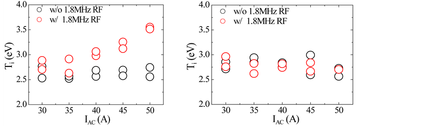
Data from FC is given in Figure 6, where Ti is plotted versus the magnetic coil current IAC with and without the RF pulse for the magnetic field directed to (a) the +z direction and (b) the −z direction. The ion cyclotron resonance (Bm = 1.18 kG) locates near the antenna for IAC = 50 A. It is evident that only in the case (a) Ti increases over the values for the base plasma with larger increment for the magnetic field closer to the ion cyclotron resonance.
Ion energy distribution function is obtained from the relation;
 , (5)
, (5)
where VC and IC are the retarding voltage and the current of the collector of FC, respectively, and VP is the plasma potential measured by LP [13] . The ion energy distribution function, i.e., the value of Equation (5) is plotted as a function of VC in Figure 7 for (a) B0//+z and (b) B0//−z with IAC = 50 A. In our device VP is negative with respect to a reference point, and the abscissa in Figure 7 that corresponds to the energy in eV spans from negative to positive. It is shown that with the application of 1.8-MHz RF f shifts toward higher energy side by 3 eV or so and becomes broader in width in the case of (a), but not in (b). The ions are heated by the RF only when the magnetic field direction is from the antenna to FC.
This is again consistent with the characteristics of field excitation of the right helical antenna. The RF field propagating to the +z direction (toward FC) is of m = −1 mode for the case (a) and of m = +1 mode for the case (b), and the m = −1 mode RF that is left-circularly polarized can heat ions near the ion cyclotron resonance in the perpendicular direction. The perpendicular energy is converted to the parallel energy in the diverging magnetic field and is observed by the parallel-aligned FC.
Te can be measured both by LP and FC. In Figure 8 left two graphs, (a) and (c), show Te measured by LP and right two graphs, (b) and (d), measured by FC. Also, upper two, (a) and (b), are for the magnetic field directed to
 (a) (b)
Figure 5. Time variation of Iis after switching on the base and 1.8-MHz RF for (a) B0//+z and (b) B0//−z.
 (a) (b)
Figure 6. Ion temperature versus the magnetic coil current IAC with and without the RF pulse for the magnetic field directed to (a) the +z direction and (b) the −z direction.
the +z direction and lower two, (c) and (d), for the −z direction. In all four graphs Te is plotted as a function of IAC. If we compare the increment in Te by the application of 1.8-MHz RF (the difference in the data values with and without RF), the incremental value is relatively large in the cases of negative-z side with B0//+z (upper left) and positive-z side with B0//−z (lower right). The m = +1 mode RF field that couples with electrons propagates toward the negative-z direction (toward LP) for B0//+z and positive-z direction (toward FC) for B0//−z as discussed in Section 2.3. This explains larger increase in Te in the two cases in Figure 8.
We see from Figures 5-8 that the right helical antenna with B0 in the +z direction can enhance the plasma production in one direction and can heat ions in the other direction simultaneously. This is the consequence of bi-directional mode-selective wave excitation of the helical antenna. A straight antenna has no capability of mode-selection, and bi-directional production and heating would not be obtained.
 (a) (b)
Figure 7. Energy distribution function with (red) and without (blue) the RF for (a) B0//+z and (b) B0//−z.

Figure 8. Left two graphs, (a) and (c), show Te measured by LP and right two graphs, (b) and (d), measured by FC. Upper two, (a) and (b), are for the magnetic field directed to the +z direction and lower two, (c) and (d), for the −z direction. In all four graphs Te is plotted as a function of IAC.
These results lead to the possibility that a magnetoplasma thruster with variable specific impulse is composed of only one helical antenna and one RF power source. The plasma production takes place at one side (say upstream side) of the antenna where the magnetic field is lower to allow HW propagation, and the ion heating takes place at downstream side where the magnetic field is higher to fulfill ion cyclotron resonance condition. We have confirmed in the experiment that the negative-z (upstream) side plasma with densities increased by the 1.8 MHz RF flows positive-z (downstream) side and exhausted through the magnetic nozzle. In reality Figure 8(a) and Figure 6(a) show the dependence on magnetic field strength of electron temperature at the negative-z side of the antenna and ion temperature at the positive-z side, respectively. This is the direct indication that by changing the magnetic field strengths in both sides of the antenna relatively, we are able to control the ratio of Te to Ti, namely, the plasma production to the ion heating. It is necessary to confirm the present findings with higher RF power, which is left for future experiments.
4. Summary
We have performed a two-dimensional numerical calculation of wave propagation and power absorption in a non-uniform plasma immersed in a non-uniform external static magnetic field, based on the hot plasma theory. It is confirmed that appropriate choice of the excitation condition of the antenna can select axial propagation direction of specific wave modes and consequently select a species that absorbs power from generated waves even in very non-uniform configuration.
We have presented the experimental evidence of bi-directional nature of the helical antenna where the plasma production and ion heating take place by the RF fields launched in opposite axial directions. The right helical antenna used in the experiment with B0 in the +z direction can enhance the plasma production in the negative-z side and can heat ions in the positive-z side simultaneously. When B0 is changed to the −z direction, the location of electron heating changes from the negative-z side to the positive-z side. This observation is consistent with the numerical calculation that the helical antenna has bi-directional nature of wave excitation.
As a result both the production and heating are accomplished simultaneously by one antenna showing that another type of the radio frequency driven magnetoplasma thruster would be achieved.
Acknowledgements
The authors thank R. Kinoshita for his help in experiments. This work was supported in part by a Grant-in-Aid for Challenging Exploratory Research (24654196) from the Japan Society for the Promotion of Science.
References
- Yasaka, Y., Hayashi, Y., Takeno, H., Nakamoto, S. and Kinoshita, Y. (2013) Bi-Directional Excitation of ICRF Waves in Non-Uniform Plasmas towards a Compact RF-Driven Magnetoplasma Thruster. Proceedings of the 31st International Conference on Phenomena in Ionized Gas, Granada, 14-19 July 2013, 2-058. http://www.icpig2013.net/papers/294_3.pdf
- Chang-Diaz, F. and Squire, J. (2004) The VASIMR Engine: Project Status and Recent Accomplishments. AIAA Aerospace Sciences Meeting and Exhibit, AIAA, Reston, 2004, Article ID: 0149.
- Bering, E., Chang-Diaz, F., Squire, J., Glover, T., Carter, M., McCaskill, G., Longmier, B., Brukardt, M., Chancery, W. and Jacobson, V. (2010) Observations of Single-Pass Ion Cyclotron Heating in a Trans-Sonic Flowing Plasma. Physics of Plasmas, 17, Article ID: A043509. http://dx.doi.org/10.1063/1.3389205
- Miljak, D. and Chen, F.F. (1998) Helicon Wave Excitation with Rotating Antenna Fields. Plasma Sources Science and Technology, 7, 61-74. http://dx.doi.org/10.1088/0963-0252/7/1/009
- Lee, C. (2008) Experimental Studies of a Helicon Plasma. Ph.D. Thesis, University of Texas, Austin, UMI 3320977.
- Yasaka, Y., Majeski, R., Browning, J. and Hershkowitz, N. (1988) ICRF Heating with Mode Control Provided by a Rotating Field Antenna. Nuclear Fusion, 28, 1765. http://dx.doi.org/10.1088/0029-5515/28/10/005
- Arefiev, A.V. and Breizman, B.N. (2004) Theoretical Components of the VASIMR Plasma Propulsion Concept. Physics of Plasmas, 11, 2942. http://dx.doi.org/10.1063/1.1666328
- Yasaka, Y., Tobita, N. and Tsuji, A. (2013) Control of Plasma Profile in Microwave Discharges via Inverse-Problem Approach. AIP Advances, 3, Article ID: 122102.
- Yasaka, Y., Fukuyama, A., Hatta, A. and Itatani, R. (1992) Two-Dimensional Modeling of Electron Cyclotron Resonance Plasma Production. Journal of Applied Physics, 72, 2652-2658. http://dx.doi.org/10.1063/1.351566
- Hojo, H., Tatematsu, Y. and Saito, T. (2007) Full-Wave Maxwell Simulations for Electron Cyclotron Resonance Heating. Fusion Science and Technology, 51, 164-167.
- Yasaka, Y. and Itatani, R. (1980) Direct Comparison between Circularly and Linearly Polarized RF Fields in ICRF Heating. Nuclear Fusion, 20, 1391-1396. http://dx.doi.org/10.1088/0029-5515/20/11/006
- Yasaka, Y., Nishino, S., Yamamoto, M., Nakamoto, S., Takeno, H. and Yonemori, H. (2012) Novel Control of Magnetoplasma Thruster by Using a Rotating Radio Frequency System. Journal of Propulsion and Power, 28, 364-370. http://dx.doi.org/10.2514/1.B34271
- Ohuchi, M., Endoh, T. and Kubota, T. (1996) Measurement of Ion Energy Distribution Functions Behind an Ion Sheath. Annual Report, Research Institute for Technology, No. 15, Tokyo Denki University, Tokyo, 77-82. (In Japanese) http://souken.dendai.ac.jp/db_pdf/1994/7.Q94-M32.pdf
NOTES

*This paper is partly based on a presentation at the International Conference on Phenomena in Ionized Gas 2013 (Yasaka [1] ).