Modeling and Numerical Simulation of Material Science
Vol.04 No.04(2014), Article ID:50393,9 pages
10.4236/mnsms.2014.44016
Flow-Optimization to Enhance Gas Quenching Efficiency for Helical Gears Specimen
Thibaud Bucquet, Udo Fritsching
Process & Methods Department, IWT Bremen, Bremen, Germany
Email: t.bucquet@iwt.uni-bremen.de
Copyright © 2014 by authors and Scientific Research Publishing Inc.
This work is licensed under the Creative Commons Attribution International License (CC BY).
http://creativecommons.org/licenses/by/4.0/


Received 25 July 2014; revised 25 August 2014; accepted 23 September 2014
ABSTRACT
Numerical simulations based on a conjugate heat transfer solver have been carried out to analyze various gas quenching configurations involving a helical gear streamed by an air flow at atmospheric pressure in a gas quenching chamber. In order to optimize the heat transfer coefficient distribution at key positions on the specimen, configurations involving layers of gears and flow ducts comprising single to multiple gears have been simulated and compared to standard batch configurations in gas quenching. Measurements have been performed covering the local heat transfer for single gears and batch of gears. The homogeneity of the heat transfer coefficient is improved when setting up a minimal distance between the gears (batch density) and when introducing flow ducts increasing the blocking grade around the gears. An offset between layers of the batch as well as flow channels around the gears plays a significant role in increasing the intensity and the homogeneity of the heat transfer in gas quenching process.
Keywords:
Heat Treatment, Gas Quenching, Helical Gears, Computational Fluid Simulation, Flow Optimization

1. Introduction
In the automotive industry, in order to achieve a sufficient hardness distribution (corresponding to a martensitic microstructure) or shape quality [1] , specific heat treatment processes are applied in the manufacturing process of parts. Gas quenching has been developed over the past years as an environmentally and economically friendly solution to replace conventional liquid or salt-based quenching [2] . Whereas conventional oil-based quenching provides heat transfer coefficients ranging from 1000 to 5000 W/(m2∙K) [3] , the polluting effect of oil requires a specific safety level and cleaning the specimen after treatment [4] . Fluid-based quenching has the major inconvenience of facing changes in its liquid phase-state and heat transfer; from film boiling to bubble boiling and finally pure convection [5] . Gas quenching defined in [6] - [8] aims at reducing the distortion potential caused by the high variations in the heat transfer intensity due to the liquid evaporation occurring during conventional liquid-based quenching.
In comparison to quenching techniques using liquids, the impact of the gas flow on the heat transfer between the quenching gas and the element to be quenched is of major importance [9] . This influence can be scaled according to the dimension of the system: at the micro scale, the solid workpiece is streamed by a complex gas flow depending on the structure of the batch (meso scale) comprising many layers of workpieces as well as racks creating a pressure drop to the incoming flow. The use of flow control elements at meso scale has been discussed in [10] for application to shaft-shaped specimen. At the macro scale of the quenching chamber, particular flow patterns arise, depending on the technical aggregates (heat exchangers, recirculation of the gas) and the geometry of the chamber (dead flow zones, chamber inlet/outlet).
Heat transfer in industrial gas quenching is described by the heat transfer coefficient h, independent of the quenching medium temperature and the specimen temperature and material properties. In industrial gas quenching, the heat transfer coefficient has been derived as [11] :
 , (1)
, (1)
where c2 is a factor related to the quenching chamber geometry.
1.1. Measurement in Industrial Gas Quenching
The heat transfer in gas quenching is analyzed using a local and an integral method to determine the heat transfer coefficient on helical gear specimen. The local determination of the heat transfer coefficient is done through measurement of the local heat flux on the specimen surface using a 5 × 5 mm Captec sensor with integrated thermocouple to monitor the specimen surface temperature [12] . The integral determination of the heat transfer is performed assuming the lumped capacitance approach described below for the gear to be investigated. The lumped capacitance assumption requires a Biot-number
 , (2)
, (2)
where l is taken as the streamwise length of the gear [13] .
Quenching conditions involving small heat transfer coefficients for material of high heat conductivity (copper, aluminum) lead the effect of internal conduction to overcome the effect on the external heat transfer by convection so that the temperature distribution is considered uniform at any time in the solid. Thus the integration of the heat equilibrium equation,
 (3)
(3)
can be reduced to a time-depending integration.
In that case, the temperature can be monitored at any point within the specimen and the integral or mean heat transfer coefficient may be calculated. Three specimen helical gears of thicknesses 20, 25 and 30 mm made of EN-AW6082 to minimize the Biot-number have been investigated during the quenching process.
The gas velocity in gas quenching process is measured using a pressure-based 7-hole, pitot probe whose orientation and calibration allow the measurement of the 3 velocity components in a 72˚ cone in relation to the incoming flow [14] .
1.2. Simulation in Industrial Gas Quenching
The simulation of the heat transfer process in gas quenching requires accurate modelling of the quenching environment (flow velocity, turbulence and chamber geometry), at the macro and meso scales. The accurate modelling of the micro scale, that is, the helical gear itself, ensures a valid computation of the heat transfer coefficient on its surface. The simulation library Open FOAM 2.0.1 provides an existing steady-state, coupled heat transfer simulation solver. The computation of the gas flow is based on Reynolds-averaged Navier-Stokes (RANS) equations using the SIMPLE-algorithm (Semi-IMplicit Pressure-Linked Equations) and the energy equation for the fluid. It provides the temperature field around the solid specimen that is used to solve the heat conduction pro- cess for the selected regions to be quenched.
Heat transfer problems simulations at large scale are ( [15] [16] ) a challenging task when defining the grid accuracy around the specimen in relation to a relevant turbulent model. [17] provided an improvement of the k-ω SST turbulence model using near-wall functions increasing the independency of the turbulence model to the first near-wall grid point distance y+. In addition to combining the k-ω turbulence model for y+ < 200 with the free-stream k-ε model for y+ > 200, near-wall functions provide a blending of the viscous and log formulations of the flow depending on the first near-wall grid point. For applications in industrial heat transfer process, this near-wall treatment has demonstrated its effectiveness for grid structures at 100 > y+ > 0.2 [18] [19] .
While the gas quenching chamber geometry is directly meshed within Open FOAM, flow ducts and the helical gears are implemented as. stl geometries in the mesh with finer resolution, so that the average grid cell number remains below 30 million cells. Inlet boundary conditions are fitted to the complex flow from the heat exchanger as velocity and turbulence components that are extrapolated from measurements in order to accurately model real gas quenching conditions. Figure 1 illustrates simulation results from steady-state coupled heat transfer with respect to measurements at 3 different positions (front side, tooth and rear side) on the helical gear using the heat flux sensors. A grid independency test has been carried out to validate the choice of the turbulence model. The various grid refinement levels are indicated in Figure 1 (right) from finer (green) to coarser (red) meshes. As y+ values from the viscous to the log-layer are used, the heat transfer coefficient remains almost constant with similar values as in the measurements. Local variations of the heat transfer coefficient are observed in areas undergoing a strong pressure gradient (recirculating flow after impinging onto the top of the gear).
2. Investigation
2.1. Flow Characteristics in Top-to-Bottom Flow Quenching Chambers
Top-to-bottom flow quenching chambers are found in industry for quenching process of gears [21] . These configurations ensure a homogeneous distribution of the main flow on the first layer of the batch, impinging directly onto the top side of the gears. The application of top-to-bottom gas quenching is done for single parts [22] , 2- dimensional [21] layers of parts and conventional 3-dimensional [7] batches. The structure of a typical top-to- bottom quenching chamber is presented in Figure 2, with the investigated quenching chamber displayed on the left and a simplified sectional view of a top-to-bottom quenching chamber on the right.
Flow distribution characteristics in the gas quenching chamber are evaluated using the pressure probe. The probe tip is pointed towards the main flow direction (along the z-axis). The probe is mounted on a positioning system scanning the investigated planes (1 - 3) shown in Figure 3. In an empty quenching chamber (without load), the flow characteristics have been evaluated using air flow at atmospheric pressure. Three planes are measured, Plane 1 (Figure 3) corresponds to the inlet flow condition, Plane 2 is the place above the batch and Plane 3 is the flow condition when reaching the outlet.
The comparison of the velocity distributions is presented in Figure 4, for planes 1 to 3 respectively from the top (inlet/heat exchanger) to the bottom (outlet) of the chamber. While the gas velocity distribution on Plane 1 obtains locally inhomogeneous distribution, presenting horizontal patterns where the velocity magnitude varies from high to low values (attributed to the heat exchanger located above this plan), the homogeneity of the distribution increases as the gas flows downwards. On Plane 3 (outlet), higher velocities are found in the front and the rear area of the chamber, where respectively the quenching chamber and furnace doors are located. These characteristics of top-to-bottom quenching chambers are due to the void or dead zones that are located besides the plane.
Numerical simulations have been performed based on the gas velocity distribution on Plane 1 as boundary conditions. The main velocity component (along the z-axis), the coefficient of variation, defined as VarCo = Sig/X and the turbulent kinetic energy have been detected and compared to simulation results for the empty flow chamber. A simulation involving a two-layer batch of helical gears has been related to the simulation/measure- ment in the empty chamber. The results are shown in Figure 5. The blue lines in all three diagrams display the empty chamber and the red lines the chamber with a batch. Empty markers indicate measurement and simulation in the empty chamber while half-full ones indicate simulations in batch-mode. Considering the streamwise ve-

Figure 1. Flow around a helical gear; velocity magnitude and heat transfer coefficient distribution on the surface from simulation (left) and heat transfer coefficient distribution over the tooth length from simulation and measurement (right).


Figure 2. Investigated quenching chamber (left) and a sectional view of a top-to-bottom flow-type quenching chamber (right) [20] .

Figure 3. Position of the planes in the empty quenching chamber (left) compared to a batch located in the quenching chamber (right).
locity measured in the center area of the chamber, simulation and measurement in the empty chamber show an increase in the mean value as the gas flows to the bottom, while the velocity decreases when the chamber con-

Figure 4. From left to right: velocity magnitude distribution in sections of the quenching chamber from top to bottom; measured.
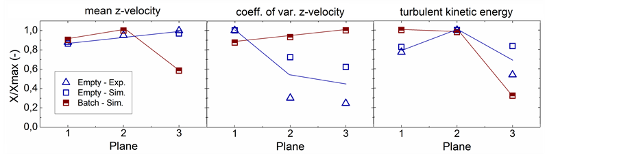
Figure 5. Results of the z-velocity, coefficient of variation and turbulent kinetic energy at various planes (1 to 3, top to bottom); measured and simulated.
tains a batch. Supposing the mass flow rate to be constant through the chamber, this decreasing value is due to the diversion of the flow on top of the batch, thus transmitting the flow momentum in the transverse directions. The increasing value in the center as no flow resistance is encountered is also described in [23] .
The increase in streamwise velocity for both empty cases in an empty chamber is due to the increase in flow uniformity shown in Figure 4, as the influence of the transverse velocity components reduces from the heat exchanger to the chamber outlet. This trend is also seen within the coefficient of variation (VarCo), increasing in the simulated case with batch. The complex batch structure is influencing the flow by increasing the velocity fluctuations while the uniformization of the flow seen in the empty chamber is characterized by a decreasing coefficient of variation. The turbulent kinetic energy (tkE) demonstrates an almost constant behavior, though the flow is becoming more homogeneous. Considering the chamber with batch, the turbulent kinetic energy is almost constant above the batch and strongly decreases through the batch itself, as the large turbulent eddies size decreases through the batch complex structure.
2.2. Influence of Flow Ducts on the Heat Transfer
Simulations have been performed for a single helical gear in various flow configurations involving flow ducts around the specimen. The influence of the flow duct dimension on the local heat transfer at 4 key positions of the helical gear is investigated. The top surface (disc front) and the bottom surface of the gear (disc gear) as well as the streamed surface (tooth front) and the reverse side of the tooth (tooth rear) are investigated as the intensity and the uniformity of the heat transfer coefficient distribution over those surfaces play a major role on achieved quality of the workpiece in the heat treatment process. Figure 6 presents the results of the simulation involving configurations of flow ducts as: 1) without flow duct; 2) with a 160 mm-diameter cylindrical flow duct, then varying the diameter to 3) 140 mm and 4) 130 mm.
The velocity distribution around the flow duct and the gear is displayed around the gear. Such a recirculation area (Figure 1) behind the helical gear without flow duct is also observed in [15] . Introducing a flow duct and reducing its diameter decreases the size and the intensity of the recirculation zone (Figure 6). The velocity is increasing and more uniformly distributed in the tooth area. In Figure 7, the effect of flow uniformization and intensification correlates positively with an improved heat transfer.
The heat transfer on the specimen surface is evaluated in Figure 7 by the mean heat transfer coefficient left and the coefficient of variation right. The introduction of flow ducts intensifies the heat transfer except for the rear surface of the gear, with the smallest cylinder diameter obtaining the best improvement. The homogeneity of the heat transfer distribution (low coefficient of variation) is found best for the 130 mm-diameter cylinder. In the flow ducts investigation at batch level, the 140 mm-diameter cylinder was used as compromise between high and homogeneous heat transfer coefficient distribution for the investigated regions of the gear.
2.3. Batch Density
Considering a single layer of helical gears in gas quenching, the packing density of the batch has been evaluated, aiming at obtaining a homogeneous local heat transfer coefficient distribution at all gear wheels. At a high batch density, the distance between a gear and its neighboring specimen is low, as represented in Figure 8, so that the local flow-interaction between gears is high, leading to stronger variations of the heat transfer coefficient from one tooth to another as the density increases. On the other hand, a too large distance between gears thus reducing the batch density is energy inefficient.
Therefore, the influence of the distance between gears is investigated for the two sides of the critical gear tooth situated closest to a neighboring gear (Figure 8). The gear side exposed to the flow is represented in red while the rear side is in blue. For gear distances ranging from 0 (gears in contact) to 20 mm, the heat transfer coeffi-

Figure 6. Velocity magnitude distribution around a helical gear with flow-duct configurations of reducing diameters; simulated.
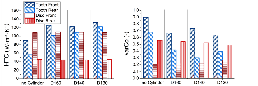
Figure 7. Heat transfer coefficient (left: average, right: coefficient of variation) at different locations for the 4 flow-duct configurations; simulated.
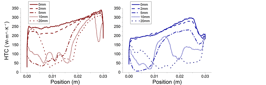

Figure 8. Local heat transfer coefficients along the front (left) and rear (right) side of a helical gear tooth for various batch densities (distance between gears in mm); simulated.
cients are plotted in Figure 8 (right) from top to bottom. At the two gear sides (front and rear), a good homogeneity and high quenching intensity are found for small distances (0 and 2 mm), while at increased distances, larger heat transfer coefficients at the top and eventually bottom part of the tooth are formed.
The flow is producing intense recirculations at higher distances, thus creating intensive heat exchange at the top, low heat exchange into the eddy in the middle of the tooth and eventually reattaching at the bottom, thus re-intensifying the heat transfer. The influence of the gear distance in the batch is displayed in Figure 9 (left) with the averaged heat transfer coefficient and corresponding standard deviations. The influence of the distance between the gears is large in the tooth area while the top and bottom sides of the gear are undergoing a less severe variation of the heat transfer intensity. As also confirmed by simulation in Figure 9 (right), a minimal gear distance between 5 and 10 mm is requested in order to ensure the most homogeneous quenching in all regions of the helical gear.
2.4. Flow Ducts Integration in Batch Configurations
Three configurations of batches involving staggered helical gears have been investigated using flow and heat transfer simulation as seen in Figure 10 (left). Confining flow ducts around helical gears may improve the quenching homogeneity in key regions of the workpiece such as the teeth. A 200 mm-height cylinder as shown in Figure 6 was investigated comprising 3 helical gears per cylinder unit. As seen in Figure 10, the integral heat transfer coefficient severely drops from the first layer to the second and third layer due to the blocking caused by the first layer in the confinement. In comparison to 200 mm-height, the 30 mm-height confinement allows a partial regeneration of the impacting flow from layer to layer. The highest heat transfer coefficients are found on the first layer with a progressive decrease to the lower layers.
An offset between parts is used (transverse in one direction) on the second layer for the third configuration of the batch in Figure 10 (bottom) utilizing the dynamic of the main flow between gears in subsequent layers. Combined with the 30 mm-height confinement, this configuration demonstrates the best results in terms of intensity and homogeneity of quenching. When considering the local quenching of the front side of a tooth from the first layer in Figure 11, the best compromise between high quenching intensity and high local homogeneity is achieved for quenching configurations with 30 mm-height cylindrical confinement.
The influence of confinement on the specimen heat transfer in gas quenching involving 2 to 3 layers in a batch with second-layer offset is summarized in Figure 12. The 30 mm-height flow ducts provides best results for the three layers in terms of quenching homogeneity and intensity. The third layer demonstrates good homogeneity but fails to reach the same level of quenching intensity when introducing a 1-directional offset at the second layer.
3. Conclusion
Measurements and simulations for evaluation of quenching heat transfer in batch configurations in industrial gas quenching of helical gears have been reported. A combination of adapted flow confinements with a layer disposition involving an offset of the second layer is improving quenching homogeneity and intensity of the quenching for the whole batch. The introduction of confinements improves the local homogeneity of the heat transfer coefficient in the tooth region of the helical gear specimen.

Figure 9. Simulated average heat transfer coefficients of a helical gear (left) and comparison (right) between measurement and simulation as a function of the batch density for the averaged heat transfer coefficient over the closest tooth region.
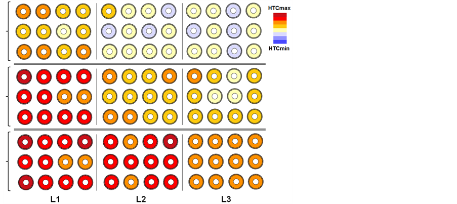

Figure 10. Average heat transfer coefficients at each layer (from left to right) for various batch configurations (from top to bottom); simulated.


Figure 11. Local heat transfer coefficient along a gear tooth (left) with average and coefficient of variation (right) for various batch configurations; simulated.
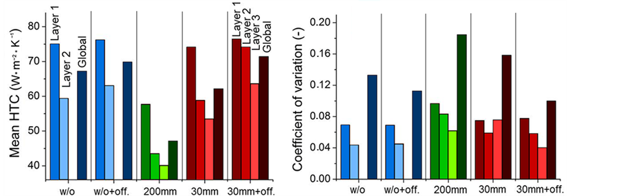
Figure 12. Mean and coefficient of variation for the integral heat transfer coefficients of the 2 and 3 layer batch configurations (without flow duct, 2nd layer offset without flow duct, with 200 mm-height flow duct, with 30 mm-height flow duct, 2nd layer offset with 30 mm-height flow duct); simulated.
Acknowledgements
The authors gratefully acknowledge support from the Forschungsgemeinschaft Industrieofenbau (FOGI e.V.) and AichelinGes.mbH, Mödling (Austria) for offering the possibility to perform in-situ test in industrial furnaces.
The project is funded by the AiF (Arbeitsgemeinschaft Industrieller for Schungsvereinigungen “Otto von Guericke” e.V.) through financial resources from the BMWi (Bundesministerium für Wirtschaft und Technologie).
References
- Clausen, B., Frerichs, F., Kohlhoff, T., Lübben, T., Prinz, C., Rentsch, R., Sölter, J., Surm, H., Stöbener, D. and Klein, D. (2009) Identification of Process Parameters Affecting Distortion of Disks for Gear Manufacture—Part II: Heating, Carburizing, Quenching. Materialwissenschaft und Werkstofftechnik, 40, 361-367. http://dx.doi.org/10.1002/mawe.200900460
- Liscic, B., et al. (2011) Quenching Theory and Technology. Taylor & Francis, London.
- Totten, G.E., Bates, C.E. and Clinton, N.A. (1993) Handbook of Quenchants and Quenching Technology. ASM Inter- national, Geauga County.
- Altena, H., Schobesberger, P. and Schrank, F. (2006) Moderne Gas-Aufkohlungstechnik für die Automobilindustrie. Gas, Wärme International, 55, 484-489.
- Stark, P. and Fritsching, U. (2011) Modeling and Simulation of Film and Transitional Boiling Processes on a Metallic Cylinder during Quenching. Journal of ASTM International, 8, 61-80.
- Stolar, P., Altena, H., Jurči, P., Klima, F. and Honzik, O. (2001) Distortion of Gear Wheels After Quenching in Gas and Oil. Proceedings of the 8th Seminar of the International Federation for Heat Treatment and Surface Engineering, IFHTSE 2001, Dubrovnik-Cavtat, 12-14 September 2001, 95-102.
- Altena, H., Jurci, P. and Stola, P. (2004) Gas and Oil Quenching Effects on Gear Distortion. Industrial Heating, 71, 45- 48.
- Atraszkiewicz, R., Januszewicz, B., Kaczmarek, Ł., Stachurski, W., Dybowski, K. and Rzepkowski, A. (2012) High Pressure Gas Quenching: Distortion Analysis in Gears after Heat Treatment. Materials Science and Engineering: A, 558, 550-557. http://dx.doi.org/10.1016/j.msea.2012.08.047
- Schüttenberg, S., Frerichs, F., Hunkel, M., Fritsching, U. and Mayr, P. (2004) Verzugskompensation Mittels Gasabschreckung in Flexiblen Düsenfeldern. HTM Härtereitechnische Mitteilungen, 59, 185-192. http://dx.doi.org/10.3139/105.100288
- Schmidt, R.-R. (2013) Zur Thermo-Fluid-Dynamik beim Hochdruckgasabschrecken: Experimentelle und Numerische Analyse der Hochdruckgasabschreckung Metallischer Bauteile zur Steigerung von Prozesshomogenität und-Intensität. Doctoraldissertation, Universität Bremen, Bremen.
- Löser, K., Heuer, V. and Schmitt, G. (2005) Auswahl geeigneter Abschreckparameter für die Gasabschreckung von Bauteilen aus verschiedenen Einsatzstählen. HTM Härtereitechnische Mitteilungen, 60, 248-254. http://dx.doi.org/10.3139/105.100347
- Captec Entreprise (2012) Heat Flux Sensor Series.
- VDI-Gesellschaft Verfahrenstechnik und Chemieingenieurwesen (2010) VDI Heat Atlas. Springer, Berlin.
- Everett, K.N., Gerner, A. and Durston, D.A. (1983) Seven-Hole Cone Probes for High Angle Flow Measurement Theory and Calibration. AIAA Journal, 21, 992-998. http://dx.doi.org/10.2514/3.8188
- Pellegrino, G., Chaffotte, F., Douce, J.F., Denis, S., Bellot, J.P. and Lamesle, P. (2005) Efficient Numerical Simulation Techniques for High Pressure Gas Quenching. Heat Treating: Proceedings of the 23rd Heat Treating Society Confe- rence, Pittsburgh, 25-28 September 2005, 320-328.
- Schmidt, R.R., Fritsching, U. and Lübben, T. (2009) Prozessmöglichkeiten zur gezielten Einstellung des Gasab- schreckens. HTM Journal of Heat Treatment and Materials, 64, 351-363.
- Menter, F., Ferreira, J.C., Esch, T., Konno, B. and Germany, A.C. (2003) The SST Turbulence Model with Improved Wall Treatment for Heat Transfer Predictions in Gas Turbines. Proceedings of the International Gas Turbine Congress, Tokyo, 2-7 November 2003.
- Menter, F.R., Kuntz, M. and Langtry, R. (2003) Ten Years of Industrial Experience with the SST Turbulence Model. Turbulence Heat and Mass Transfer, 4, 625-632.
- Mangani, L. and Bianchini, C. (2007) Heat Transfer Applications in Turbomachinery. Proceedings of the OpenFOAM International Conference, London.
- von Starck, A., Mühlbauer, A. and Kramer, C. (2005) Handbook of Thermoprocessing Technologies: Fundamentals, Processes, Components, Safety. Vulkan-Verlag GmbH, Essen.
- Heuer, V., Faron, D.R., Bolton, D., Lifshits, M. and Löser, K. (2013) Distortion Control of Transmission Components by Optimized High Pressure Gas Quenching. Journal of Materials Engineering and Performance, 22, 1833-1838. http://dx.doi.org/10.1007/s11665-013-0547-6
- Stratton, P.F. and Ho, D. (2000) Individual Component Gas Quenching. In: 5th ASM Heat Treatment and Surface En- gineering Conference in Europe and the 3rd International Conference on Heat Treatment with Atmospheres, Gothen- burg, 7-9 June 2000, 367-375.
- Ward-Smith, A.J., Lane, D.L., Reynolds, A.J., Sahin, B. and Shawe, D.J. (1991) Flow Regimes in Wide-Angle Screened Diffusers. International Journal of Mechanical Sciences, 33, 41-54.