Modeling and Numerical Simulation of Material Science
Vol.2 No.2(2012), Article ID:18403,13 pages DOI:10.4236/mnsms.2012.22002
Cellular Automata Simulation of Gap-Filler Dissolution during Transient Liquid Phase Bonding of Single Crystal Materials
Department of Mechanical and Manufacturing Engineering, University of Manitoba, Winnipeg, Canada
Email: *olanrewaju.ojo@ad.umanitoba.ca
Received December 15, 2011; revised January 28, 2012; accepted February 9, 2012
Keywords: Cellular Automata; Transient Liquid Phase Bonding; Single Crystal; Powder Dissolution
ABSTRACT
A new numerical model is developed using a Cellular Automata (CA) method to study the liquid-phase dissolution behavior of gap-filler powder particles in interlayer powder mixture during transient liquid phase (TLP) bonding process. The model prediction of microstructural evolution in TLP joint between single crystal substrates show that formation of misoriented stray-grains results from incomplete liquation of the gap-filler powder particles. In contrast to what is generally assumed and reported, numerical calculations coupled with experimental verification show that under properly selected process parameters, complete melting of the gap-filler powder particles is possible. This is imperative to prevent the formation of misoriented stray-grains and maintain single crystallinity during TLP bonding of single crystal materials. The dependence of complete melting of the gap-filler particles on salient TLP bonding parameters are analyzed and discussed.
1. Introduction and Background
Single crystal nickel-base superalloys are new generation heat resistant materials used in the manufacture of section components in aircraft and land-based power-generation turbine engines due to their remarkable mechanical properties at elevated temperatures [1]. Prolonged operations under these severe conditions often lead to degradation due to creep, thermo-mechanical fatigue and oxidation. Due to the high cost of these materials, it is often more economical to repair the damaged components. However, conventional repair techniques applied on precipitation hardened superalloys such as fusionwelding methods are severely limited due to the high susceptibility of these alloys to heat affected zone cracking [2] and the possible formation of stray grains in single crystal and directionally solidified materials [3,4]. Furthermore, conventional brazing methods result in the formation of hard and brittle eutectic-type micro-constituents in brazement, which degrades the mechanical properties of brazed materials [2,5].
Transient liquid phase (TLP) bonding has evolved from conventional brazing as a method to prevent the formation of deleterious non-equilibrium solidification micro-constituents. In TLP bonding, a thin layer of filler alloy, rich in melting-point depressant (MPD) solute, is sandwiched between two solid base materials and the entire assembly is heated to the bonding temperature. At the bonding temperature, the filler alloy melts and rapidly attains equilibrium at the liquid-solid interfaces through base-alloy melt-back dissolution process. Following the dissolution stage, a solid-state diffusion of the melting point depressant (MPD) element away from the liquid interlayer into the solid substrate occurs, which results in a decrease in the volume of liquid that can be maintained at equilibrium, thus, causing isothermal solidification to proceed inward from the solid mating surfaces [5]. Following the isothermal solidification stage, the joint is homogenized either at the bonding temperature or at some lower temperature [2,3]. Qualitatively, the TLP bonding technique relies on the variation of liquidus temperature of an alloy with composition and the fact that concentration variation in an inhomogeneous alloy can cause localized melting when the bulk of the material remains solid. The bonding process is ideal for joining base materials which are inherently susceptible to hot cracking or post-weld heat treatment cracking problems and can even be used for joining of dissimilar materials [2,3,5].
Liquid-phase dissolution of the base-material, a phenomenon also known as “liquid-metal erosion”, occurs during the initial stage of TLP bonding, as the interlayer liquid tries to attain equilibrium solute concentration with the solid substrate. Liquid-phase erosion of the basematerial causes increased gap width during bonding. An approach that is commonly used to reduce base-material erosion while enriching the joint region with base-material alloying elements involves the use of composite powder mixture as interlayer material. The composite powder mixture consists of commercial filler alloy that contains MPD element and a gap-filler powder that is essentially free of the MPD element, possibly the basematerial powder. Optimization of the process parameters is essential in obtaining a superior joint [6] since partial melting of the gap-filler particles can occur and the unmelted remaining solid components can lead to misoriented stray-grains formation at the joint. Huang et al. [7], investigated the diffusion bonding of Al-based dissimilar composites by using Al-Si, Al-Cu and Al-Si-SiC powders as fillers. They reported that the segregation of SiC particles and formation of porous zones at the joint lead to a reduction of the joint shear strength. They also reported an increase in the shear strength of the joint with increasing temperature and holding time. Wu et al. [8] also investigated wide gap bonding of stainless steel to Ni-base superalloy. They reported that during the bonding process, the gap-filler particles reacted with the liquid and dissolved into the liquid but were incompletely melted and provided the necessary capillary force to retain the molten filler material, which would otherwise be overly fluid to bridge the gap faying surfaces. Zhuang and Eager [9] experimented with powder TLP bonding by using metallic powders coated with a small amount of material that contained a MPD solute. They reported that the coating material and the thickness of the deposit influence porosity formation within the joint. Two different powder materials, Ni-20Cr and 304L stainless steels, both of which were coated with Ni-10P, to join 304L stainless steel base alloy. They reported joints with good mechanical properties when the Ni-20Cr powder was used, while inferior properties are obtained by using the 304L powder, which was attributed to residual porosity observed within the joint. To reduce porosity, they proposed a liquid infiltration approach, where a thin foil that contained a MPD solute is inserted between the base material and the powder mixture.
The technological merits of the composite powder mixture and its application to joining of single crystal materials is generally avoided due to formation of straygrains within the joint region, which compromises high temperature properties of bonded materials. However, the understanding of the dissolution behaviour of gapfiller powder particles by molten filler alloy, which could influence formation of the stray-grains, is limited due to the large number of process and material parameters that affect the final joint microstructure and performance. Mathematical modeling, which is imperative to adequate understanding of the gap-filler powder dissolution process, is very limited due to certain difficulties. Current analytical models [10-13] are only capable of providing an overall estimate of the time required to achieve complete isothermal solidification and are not suitable for simulating powder dissolution. The large number of powder particles results in a large number of particle-liquid boundaries which need to be effectively and efficiently tracked in order to study changes to the powder particles with time. The topological changes of the dissolving or growing powder particle also pose difficulties that can not be addressed by available 1-D numerical TLP bonding models [14-16]. At any time, a powder particle-liquid interface may break up, or join with neighboring interfaces. This poses severe difficulties when conventional interface-tracking methods are used. Additionally, the dissolution of powder occurs rapidly compared to the isothermal solidification stage. Therefore, different time stepping scales are required to capture the intricate changes to the powder particles.
To study the evolution of interfaces, conventional interface-tracking methods would involve the introduction of nodal points at the interface and solving the general transport equations using moving mesh techniques to ensure conformance of the mesh with the moving interface. While the method has the advantage of representing the interface directly, it is very sensitive to topological variations. Therefore, inaccuracies may arise when nodal points at the interface get too close together or too far apart. As a result, to ensure simulation validity, an extra step is generally required to either explicitly remove or add nodal points, depending on the position of the nodes relative to one another. Moreover, major difficulties can be encountered when an interface breaks apart or when interfaces merge together which requires explicit handling of nodal points at the interface and requires remeshing to conform to the new interfacial geometries. The special attention needed to mitigate these problems is rather cumbersome, and as a result, interface-tracking techniques are often limited to relatively simple geometries and interfacial topologies.
CA methods mitigate some of the issues involved in the conventional interface-tracking methods by discritizing the domain into cells where the evolution of each cell is dependent on the states of its immediate neighboring cells. A cellular automaton is a dynamical system, in which space, time, and the states of the system are discrete. It was first developed by John Von Neumann in 1963 after a suggestion by Ulam [17] as a means to study universal copiers and destructors. It was later analyzed by Wolfram [18] in the 1980’s as part of his work on analyzing complexity. CA methods provide a frame work to simultaneously study changes in the entire computational domain. This makes the method very useful in studying microstructural evolution and studying complex systems. It can also provide fast implementation on parallel computers due to the inherent parallelism of the CA structure. CA methods applied in materials science generally involve discritizing the microstructure into cells where each cell can have a finite number of states such as concentration, temperature, or phase order parameter. Transition rules are imposed to determine cell evolution depending on the states of its neighboring cells, which can be a Neumann-type or Moore-type, in a square cell lattice. The basic idea of CA for phase change studies is to mimic interface propagation by capturing transition from nearby liquid cells to the solid body according to certain criteria. It is assumed that three kinds of possible cells exist within a simulation domain i.e. solid, liquid and interface cells. Solid cells have a solid fraction of 1, liquid cells have a value of 0, and interface cells have a solid fraction which varies between 0 and 1. Cell capturing rules can be applied to calculate the future solid fraction in each cell, depending on the solutal and thermal distribution in the domain. In CA, the interface is not explicitly tracked like in interface-tracking methods. However, the location of the interface can be obtained by determining the cells where the solid fraction varies from 0 to 1. As a result, the CA method can capture complex interfacial dynamics with great efficiency and its computational requirements (memory and time) are much lower than other methods such as phase-field methods [19]. A review of CA modeling of microstructural evolution has been presented by Janssens [19] and He et al. [20]. It has been used for modeling structural evolution during solidification [21-23]. The method has been also applied to study microstructural evolution during solidstate recrystallization and growth [24]. CA methods has also been coupled with other numerical methods such as the finite difference method [25], the finite volume method [26], the finite element method [27,28] and more recently the lattice Boltzmann method [29].
In the present work, the CA method is used to study the dissolution of solid powder particles during TLP bonding. The mathematical formulation and implementation will be discussed in the following sections followed by the results and discussion.
2. Formulation and Implementation of the Cellular Automata Numerical Model
A two-dimensional Euclidean lattice  that is discretized into square cells is considered (Figure 1). A cell
  in the domain hold a finite set of possible states namely, solid, liquid and interface and has a finite set of Moore-type neighboring cells:
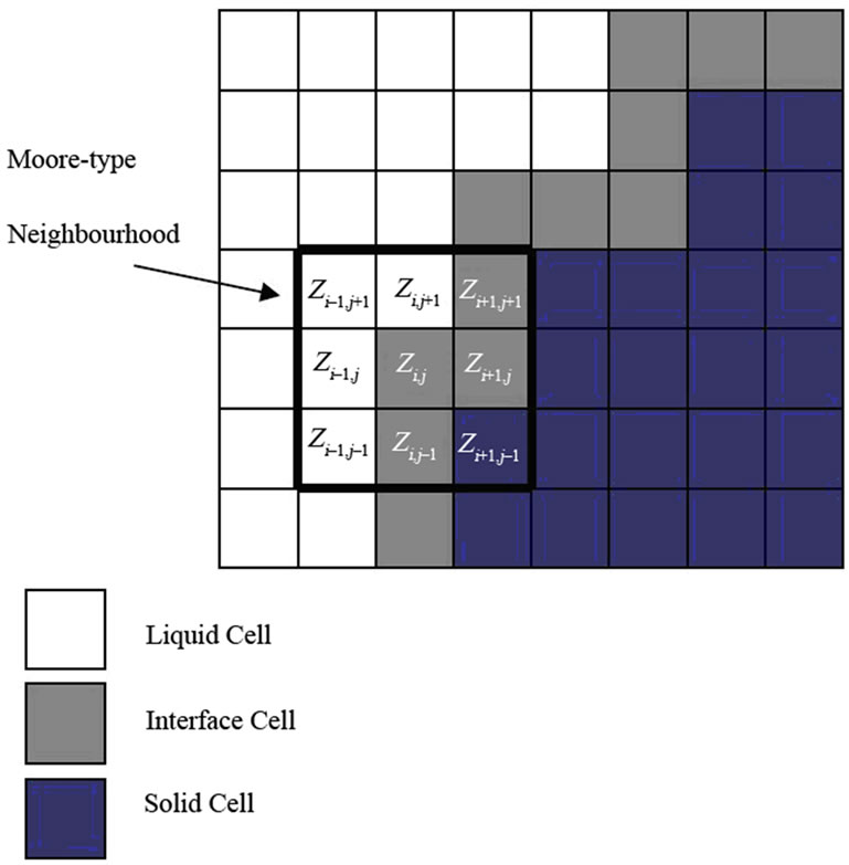
Figure 1. Schematic illustrating the possible cell states and Moore-type neighborhood used in the CA model.
 .
.
In this work, each cell  holds a finite number of associated data namely, temperature T, composition C, spin index S, and solid-fraction f. The spin index S represents the crystallographic orientation of a powder particle, which is 0 in liquid and can be any integer number in a solid phase. The solid fraction, f, can vary from 0 to 1 in any given cell. A cell having an f value of 0 is a completely liquid cell, a value of 1 is completely solid, and cells having values 0 < f < 1 define an interface cell.
For the purposes of our analysis, at any given time, determination of the volume fraction of residual solid is more essential than the explicit location of the liquidpowder particle interfaces. Therefore, the basic idea of the current model is to calculate the evolution of the solid fraction in each cell instead of directly tracking the interface motion between a powder particle and the liquid. This approach gives a good representation of evolution of the powder particles while avoiding having to explicitly track the large number of powder-liquid interfaces and can easily handle topological changes and interfacial dynamics such as splitting and joining.
The liquid phase has an initial solute concentration CF and the solid particles have an initial solute concentration Cm. Solute diffusion in the liquid phase is expressed by:
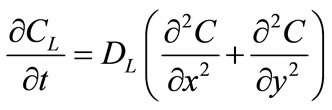 (1)
(1)
Similarly, solute diffusion in the solid particles is expressed as:
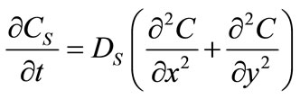 (2)
(2)
where  and
and  are the diffusivities in the solid and liquid cells, respectively. The increase in the solid fraction
  is calculated using [26]:
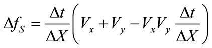 (3)
(3)
where  is the time step,
  is the cell size,
  and
and  represent the velocity of the interface cells in the x and y directions. These velocities are calculated using:
 (4)
(4)
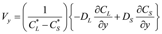 (5)
(5)
where  and
and  are the equilibrium liquidus and solidus concentrations at the interface cells, respectively. At any given time, curvature of the liquid-solid interface is calculated using the procedure proposed by Sasikumar et al. [30], where the number of cells in the extended neighborhood of the interface cell is counted. For example, a 7 × 7 square of cells, which yields a total area of
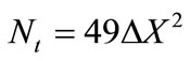 , is drawn around the cell of interest and the number of solid fraction,
  , in the region is determined. The value for curvature
 ![]() can then be found from:
can then be found from:
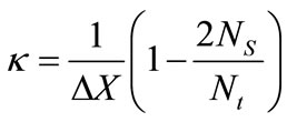 (6)
(6)
To calculate the concentrations in the liquid and solid, a typical cell-centered fully implicit transient finite difference method is used to solve Equations (1) and (2). An identical square mesh was used for both the CA and the finite difference computations. Even though a fully implicit transient method is used to solve the concentration equations, there is still a critical time step that must not be exceeded to ensure that the interface velocity is not too high to cause instabilities in the CA solution. The critical time step is calculated from [31]:
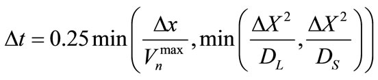 (7)
(7)
where  is the maximum velocity of the interface cells. The interface velocities and solute concentrations are calculated under the following assumptions:
1) The molar volume is assumed to be constant in both the liquid and solid. This assumption has been used in previous numerical models [14-16,32] and it yielded good agreement with experimental results.
2) The diffusivity of the MPD solute is independent of concentration. Due to the lack of extensive experimental thermodynamic data on how the localized diffusion of the MPD solute is affected by concentration during TLP bonding, this assumption is commonly used in existing numerical TLP bonding models [14-16,32].
3) There is negligible liquid flow due to convection and stirring in the liquid. In the present experimental work there was no induced convection in the liquid.
In the present model, powder particles are generated and randomly distributed in the domain such that the initial volume fraction of solid in the computational domain is equal to some user specified value. A randomly generated spin index is produced and assigned to each particle to represent its crystallographic orientation. Interface cells are defined and initial solute concentrations in the solid particles, the liquid and interfaces are subsequently defined. Since the initial distribution of the powder particles in the liquid is randomly generated, some particles may share a boundary. If any two particles have different spin index S then the boundary cells are set to be the interface cells. However, if the two particles share the same spin index, they are considered as a single particle. A flow chart of the computational algorithm used for the model is shown in Figure 2 and it can be summarized as follows:
1) Seed sites are randomly chosen and grown until the user specified powder-to-liquid ratio is achieved;
2) Future solute concentrations in the liquid and solid phases are simultaneously calculated for one time step;
3) A cell is randomly chosen, and if it is determined to be liquid or solid then it is left unchanged. However, if it is an interface cell, interface cell velocities in the X and Y directions are calculated;
4) The change in solid fraction, ![]() f, is calculated to update the existing solid fraction in the interface cell;
f, is calculated to update the existing solid fraction in the interface cell;
5) If the new solid fraction in the interface cell is larger than 1, the solid fraction is set to 1 and the extra solid fraction is evenly distributed among identified neighboring liquid cells. The cells subsequently become interface cells and the interfacial curvature and concentrations is calculated. Likewise, if the solid fraction of the cell is less than 0, the solid fraction is reset to 0. The neighboring solid cells are then determined and the difference in solid fraction is evenly extracted from the neighboring solid cells. The solute concentration in the neighborhood is also adjusted to account for the change in solid fraction;
6) Cell spin index is updated depending on particle growth or dissolution. A dissolved solid cell has a spin index of zero;
7) Steps 3 - 6 are repeated such that all the cells in the

Figure 2. Flow chart of the computational algorithm for the cellular automata model.
domain are scanned at least once;
8) All data associated with each cell are updated and steps 2 - 7 are repeated for the next time step.
3. Results and Discussion
To study the influence of bonding temperature on the dissolution behavior of gap-filler powder particles by molten filler alloy, numerical simulations were carried out by using the new model for a Ni-B system at an initial bonding temperature of 1180˚C. The liquid phase at the start of the simulation is a molten alloy of nickel and boron with a boron concentration of 17 at%, while the gap-filler powder consists of nickel particles that are initially free of boron. Figure 3 shows the normalized boron distribution in the liquid and the solid particles after 20 time steps for 50 randomly distributed powder particles with an average solid-to-liquid volume ratio of 10%. A number of important observations can be made from the simulations. As can be seen at first glance, after 20 time steps, the liquid is rich in boron while the center region of the particles has the lowest boron concentration while localized depletion of the solute is observed in the liquid at regions closest to the liquid-solid interfaces. Further increase in holding time resulted in further diffusion of boron into the solid particles along with dissolution of the solid particles as shown in Figure 4. Since initial liquid and solid concentrations near the liquidsolid interfaces are different than the local equilibrium concentrations at the bonding temperature, there exists a driving force to reach this equilibrium which results in dissolution of the solid particle to reduce solute concentration in liquid. A larger amount of solute depletion in liquid will exit at regions where density of powder particle distribution is high while regions free of powder particles have high solute concentrations. The decrease in the solute concentration in the liquid to the equilibrium
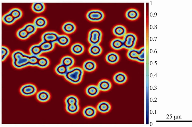
Figure 3. Numerically simulated micrograph of normalized solute distribution in the liquid and gap-filler powder particles after 20 time steps.
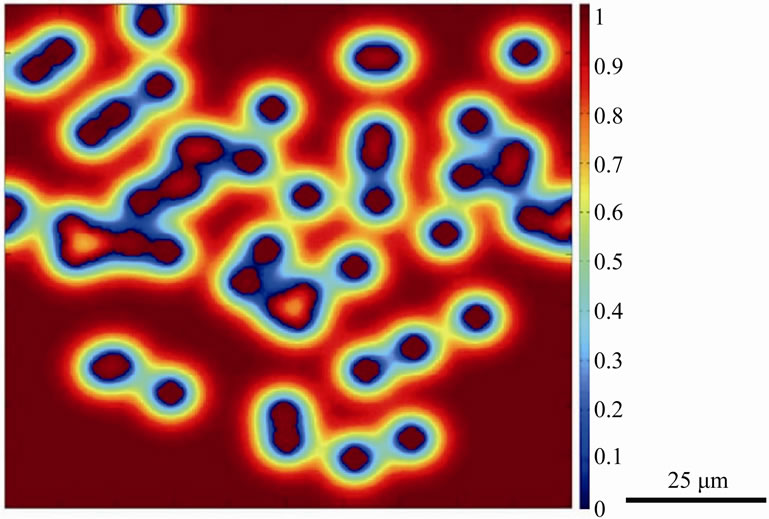
Figure 4. Numerically simulated micrograph of normalized solute distribution in the liquid and gap-filler powder particles after 60 time steps.
concentration with increase in time, by the dissolution of the gap-filler powder particles, was achieved without the complete dissolution of all gap-filler particles. The incomplete dissolution of the solid particles resulted in the formation stray-grains within the joint region after complete isothermal solidification of the interlayer liquid, as shown in Figure 5. The simulation confirms experimental observations reported in the literature that incomplete dissolution of gap-filler powder particles produces formation of stray grains during TLP bonding of single crystal substrates [3,4].
The effect of increase in temperature on the gap-filler powder dissolution was simulated by increasing the temperature to 1250˚C, while keeping all the other parameters the same. As shown in Figures 6(a)-(c), dissolution of the powder particles gradually occurred until the particles were completely dissolved after 400 time steps. It can also be observed that agglomerated particles will gradually dissociate and breakup from their immediate neighbor during the dissolution process. Detecting this behavior using the conventional interface-tracking methods would have posed many computational difficulties, however, it can be reliably simulated by using the CA method. The complete dissolution of the gap-filler powder particles resulted in a joint with matching crystallographic orientation with the substrate material, without the formation of stray grains (Figure 7). The simulation results, thus, show that in contrast to what is generally reported, complete dissolution of gap-filler powder particles is possible during the bonding process and when it occurs, it produces joint free of stray-grains upon complete isothermal solidification.
Variation of residual powder particles with bonding temperature is illustrated in Figure 8, which shows that an increase in temperature produces increased powder dissolution with complete dissolution occurring at 1250˚C. Aside from temperature, other salient bonding parame-

Figure 5. Numerical simulation spin index distribution showing formation of misoriented stray-grains in TLP joint between single crystal substrates.
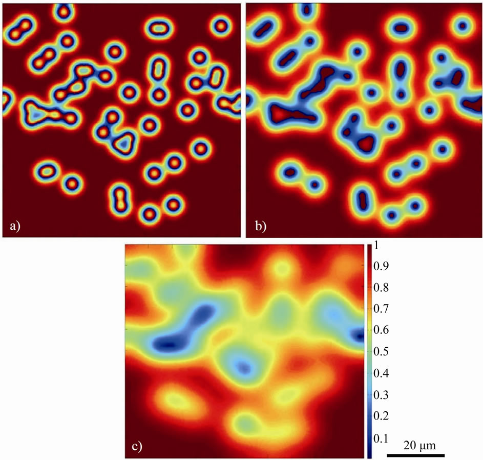
Figure 6. Numerically simulated normalized solute distribution in liquid and gap-filler particles, showing gradual dissolution (a), (b) and then eventual complete dissolution (c) of the gap-filler powder particles.
ters that influence the occurrence of complete gap-filler powder dissolution, which is not usually reported, are discussed next.
To study the effect of ratio of gap-filler powder to filler powder, Raf, on the extent of dissolution of the gap-filler particles, numerical simulations were performed by varying Raf from 10% - 60% at 1250˚C bonding temperature. The variations of residual gap-filler particles remaining with time, for the different values of Raf are shown in Figure 9. Complete dissolution of powder particles occurred with Raf values of 10%, 30% and 40% powder mixtures, while the particles experience incomplete dissolution in the 50% and 60% mixtures. The results show that the Raf has a significant influence on the occurrence of partially dissolved powder particles that result in the formation of stray-grains. As the Raf increases, the amount of solid present will exceed the amount of solid dissolution required to dilute the molten filler alloy in order to attain the equilibrium solute concentration at the bonding temperature. In addition, as
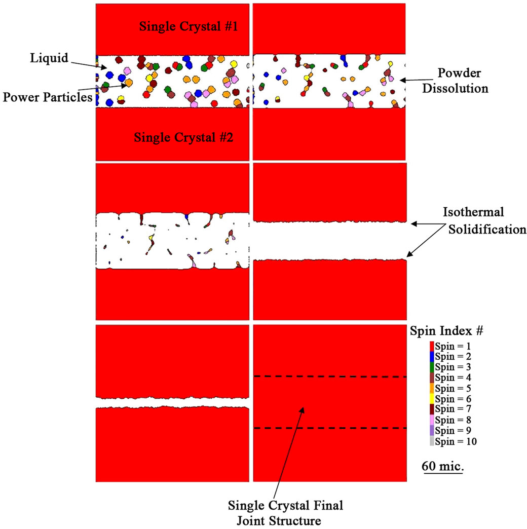
Figure 7. Numerical simulation spin index distribution showing gradual to complete dissolution of the gap-filler powder particles and a final single crystal joint formed after complete isothermal solidification of the interlayer liquid.
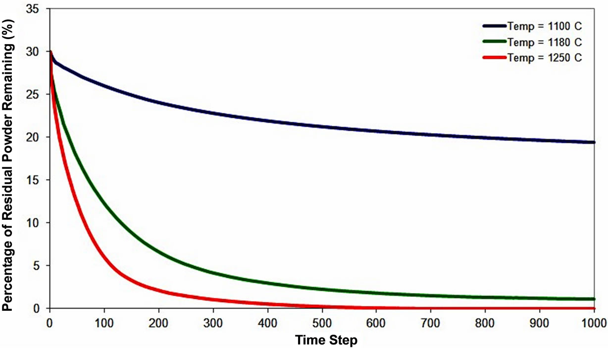
Figure 8. Numerical simulation result of gap-filler particles dissolution behavior at different holding temperatures.
more gap-filler powder is added, the amount of solute rich liquid that requires dilution decreases. These concurrent effects can explain the observation of complete gap-filler powder dissolution with reduction in Raf.
Commercial filler alloy powders are produced with varying composition of MPD solute. In the present work, the influence of concentration of MPD solute in the filler alloy powder, CF, on dissolution of gap-filler powder particles was also investigated. The simulation was performed with a Raf value of 30% and at a bonding temperature of 1100˚C. As shown in Figure 10, the extent of the gap-filler powder dissolution increases with increase in CF. At a given temperature, an increase in the initial concentration of the MPD solute in the filler alloy raises the amount of dilution of the molten filler required for the liquid to attain the equilibrium composition, which in turn increases the dissolution of the gap-filler powder particles.
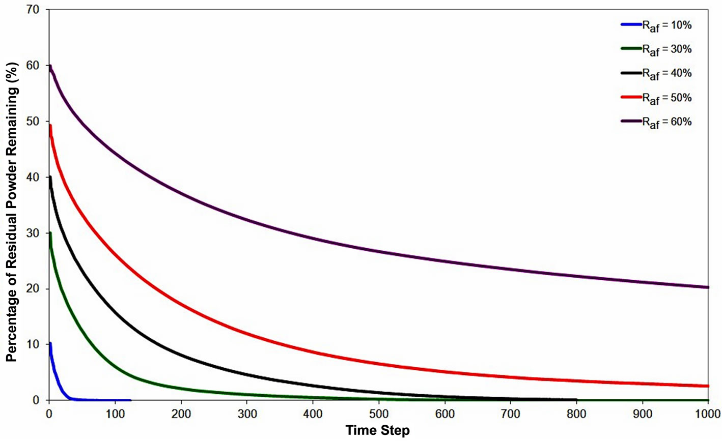
Figure 9. Numerical simulation result showing the effect of gap-filler powder to filler powder ratio on the gap-filler particles dissolution behavior.
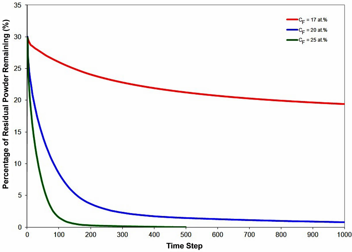
Figure 10. Numerical simulation result showing the effect of initial MPD solute concentration in liquid on gap-filler powder dissolution behavior.
Hence, the numerical calculations performed in this work indicate that, even though it is not generally reported, depending on the combination of various factors, complete dissolution of the gap-filler powder particles by molten filler alloy can occur during TLP bonding. The CA model also shows that under such a situation of complete liquid phase dissolution of the gap-filler powder particles, the use of composite powder mixture can be used to produce stray-grains-free joint with matching crystallographic orientation with the substrate material. The model predictions were experimentally verified by using a commercial Ni-Cr-B filler alloy powder (Nicrobraz 150) and IN 738 superalloy as gap-filler powder with IN 738 superalloy as the substrate material. The chemical compositions of the filler alloy and IN 738 are listed in Table 1. The experiments were performed at different temperatures using a composite powder mixture of the filler alloy and gap-filler alloy with a Raf value of 30%. At temperatures below 1150˚C, the molten filler alloy only caused partial melting of the gap-filler powder particles. A micrograph of an incompletely melted power mixture is shown in Figure 11. An increase in the temperature to 1150˚C resulted in complete liquid-phase dissolution of the gap-filler particles by the molten filler alloy (Figure 12), Complete isothermal solidification of the fully melted composite powder mixture produced a joint that is free of stray-grains between single crystal IN 738 substrates (Figure 13).
Orientation imaging microscopy (OIM) analyses were performed on the complete isothermally solidified joint produced with the composite powder, to evaluate the shows {100}, {110} and {111} stereographic pole fig-
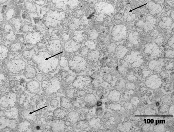
Figure 11. Microstructure of a partially melted powder mixture. The arrows show residual gap-filler powder particles.
ures of randomly chosen nine points within the substrate crystallographic orientation relationship between the joint and the single crystal substrate and to confirm the preclusion of stray-grains within the joint. Figure 14 and joint region. The analysis shows that the nine points are projected at nearly the same location within the stereographic pole figures. Also, the result of an OIM mapping technique that uses color to represent crystallographic orientation is presented in Figure 15. The results of both OIM techniques (Figures 14 and 15) confirm that the SX substrate material and the joint region exhibit matching crystallographic orientations. The experimental results, thus, corroborate the numerical model prediction that indicates complete melting of powder mixture of filler alloy and gap-filler alloy is possible during TLP bonding and complete isothermal solidification of the liquid produced by such fully melted mixture can prevent forma-
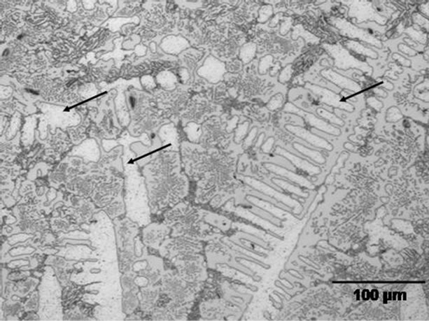
Figure 12. Microstructure of completely melted interlayer powder mixture. The arrows show dendrites formed after solidification.
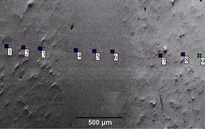
Figure 13. Micrograph of a joint free of stray-grains between single crystal IN 738 substrates produced with composite powder mixture with a Raf value of 30% at 1150˚C.

Table 1. Nominal materials composition.
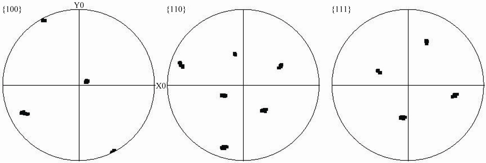
Figure 14. {100}, {110} and {111} stereographic pole figures of the analyzed locations shown in Figure 12.

Figure 15. Result of orientation imaging microscopy mapping across the SX IN 738 substrates and the joint region shown in Figure 12. The same color of the joint region and the substrates indicates matching crystallographic orientation relationship.
tion of stray grains during joining of single crystals.
4. Summary and Conclusions
1) A new CA numerical model has been developed to study the dissolution of solid gap-filler powder particles by molten filler alloy during the TLP bonding process.
2) The numerical analysis shows that the liquid-phase dissolution of the powder particles is significantly influenced by temperature, the initial concentration of MPD solute in the filler alloy and the ratio of the gap-filler alloy to the filler alloy in the composite powder mixture.
3) The use of spin index, S, in the theoretical model, to represent the crystallographic orientation of each powder particle shows that incomplete dissolution of the gapfiller particles would result in the formation of misoriented stray-grains in a joint between single crystal substrates.
4) In contrast to what has been generally assumed and reported, numerical calculations show that complete dissolution of the gap-filler particles by the molten filler is possible and complete isothermal solidification of the resultant liquid would produce a joint having a matching crystallographic orientation with single crystal substrate.
5) The predictions of the numerical model were experimentally verified and complete melting of a composite powder mixture was observed and it produced a joint free of misoriented stray-grains in a single crystal IN 738 superalloy substrate.
5. Acknowledgements
The authors gratefully acknowledge financial support by NSERC of Canada.
REFERENCES
- R. A. MacKay, R. L. Dreshfield and R. D. Maier, “Anisotropy of Nickel-Base Superalloy Single Crystals,” Proceedings of the 4th International Symposium for Superalloys, Seven Springs, Champion, 21-25 September 1980, pp. 385-394.
- D. S. Duvall and W. A. Owczarski, “Further Heat-AffectedZone Studies in Heat Resistant Nickel Alloys,” Welding Journal, Vol. 46, No. 9, 1967, pp. 423-432.
- W. F. Gale and D. A. Butts, “Transient Liquid Phase Bonding,” Science and Technology of Welding Journal, Vol. 9, No. 4, 2004, pp. 283-300. doi:10.1179/136217104225021724
- P. C. Prakash, A. Merati, X. Huang and J.-F. Thibault, “Advanced Technologies for Repair of Single Crystal Turbine Blades,” Proceeding of 43rd Conference of 450 Metallurgist, Hamilton, 22-25 August 2004, p. 413.
- D. S. Duvall, W. A. Owczarski and D. F. Paulonis, “Transient Liquid Phase Bonding: A New Method for Joining Heat Resistant Alloys,” Welding Journal, Vol. 53, No. 4, 1974, pp. 203-214.
- P. S. Kotval, J. D. Venables and R. W. Calder, “The Role of Hafnium in Modifying the Microstructure of Cast Nickel-Base Superalloys,” Metallurgical and Materials Transactions B, Vol. 3, No. 2, 1972, pp. 457-462. doi:10.1007/BF02642049
- J.-H. Huang, Y.-L. Dong, Y. Wan, X.-K. Zhao and H. Zhang, “Investigation on Reactive Diffusion Bonding of SiCp/6063 MMC by Using Mixed Powders as Interlayers,” Journal of Materials Processing Technology, Vol. 190, No. 1-3, 2007, pp. 312-316. doi:10.1016/j.jmatprotec.2007.02.028
- X. W. Wu, R. S. Chandel, H. P. Seow and H. Li, “Wide Gap Brazing of Stainless Steel to Nickel-Based Superalloy,” Journal of Materials Processing Technology, Vol. 113, No. 1-3, 2001, pp. 215-221. doi:10.1016/S0924-0136(01)00596-9
- W. D. Zhuang and T. W. Eager, “Liquid Infiltrated Powder Interlayer Bonding: A Process for Large Gap Joining,” Science and Technology of Welding and Joining, Vol. 5, No. 3, 2000, pp. 125-135. doi:10.1179/136217100101538128
- Y. Zhou, “Analytical Modeling of Isothermal Solidification during Transient Liquid Phase (TLP) Bonding,” Journal of Materials Science Letters, Vol. 20, No. 9, 2001, pp. 841-844. doi:10.1023/A:1010914813875
- Y. Zhou, W. F. Gale and T. H. North, “Modeling of Transient Liquid Phase Bonding,” International Materials Review, Vol. 40, No. 5, 1995, pp. 181-196. doi:10.1179/095066095790151160
- Y. Nakao, K. Nishimoto, K. Shinozaki and Y. Kang, “Transient Liquid Insert Metal Diffusion Bonding of NickelBase Superalloys,” Joining Advanced Materials, Chapman and Hall, London, 1990, pp. 129-144.
- I. Tuah-Poku, M. Dollar and T. B. Massalski, “A study of the Transient Liquid Phase Bonding Process Applied to an Ag/Cu/Ag Sandwich Joint,” Metallurgical and Materials Transactions A, Vol. 19, No. 3, 1988, pp. 675-686.
- Y. Zhou and T. H. North, “Kinetic Modeling of Diffusion-Controlled, Two-Phase Moving Interface Problems,” Modeling and Simulation in Materials Science and Engineering, Vol. 1, No. 4, 1993, pp. 505-516. doi:10.1088/0965-0393/1/4/012
- T. C. Illingworth and I. O. Golosnoy, “Numerical Solutions of Diffusion-Controlled Moving Boundary Problems Which Conserve Solute,” Journal of Computational Physics, Vol. 209, No. 1, 2005, pp. 207-225. doi:10.1016/j.jcp.2005.02.031
- J. F. Li, P. A. Agyakwa and C. M. Johnson, “A fixedGrid Numerical Modeling of Transient Liquid Phase Bonding and Other Diffusion-Controlled Phase Changes,” Journal of Materials Science, Vol. 45, No. 9, 2010, pp. 2340-2350. doi:10.1007/s10853-009-4199-8
- S. Ulam, “Random Processes and Transformations,” Proceedings of International Congress of Mathematicians, Cambridge, 30 August-6 September 1950, pp. 264-275.
- S. Wolfram, “Universality and Complexity in Cellular Automata,” Physica D: Nonlinear Phenomena, Vol. 10, No. 1-2, 1984, pp. 1-35.
- K. Janssens, “An Introductory Review of Cellular Automata Modeling of Moving Grain Boundaries in Polycrystalline Materials,” Mathematics and Computers in Simulation, Vol. 80, No. 7, 2010, pp. 1361-1381. doi:10.1016/j.matcom.2009.02.011
- H. Yang, C. Wu, H. W. Li and X. G. Fan, “Review on Cellular Automata Simulations of Microstructure Evolution during Metal Forming Process: Grain coarsening, recrystallization and phase transformation,” Science China Technological Sciences, Vol. 54, No. 8, 2011, pp. 2107- 2118. doi:10.1007/s11431-011-4464-3
- Y. Liu, Q. Y. Xu and B. C. Liu, “A Modified Cellular Automaton Method for the Modeling of the Dendritic Morphology of Binary Alloys,” Tsinghua Science and Technology, Vol. 11, No. 5, 2006, pp. 495-500. doi:10.1016/S1007-0214(06)70225-5
- W. Wang, P. D. Lee and M. McLean, “A Model of Solidificaiton Microstructure in Nickel-Based Superalloys: Predicting Primary Dendrite Spacing Selection,” Acta Materialia, Vol. 51, No. 10, 2003, pp. 2971-2987. doi:10.1016/S1359-6454(03)00110-1
- K. Kremeyer, “Cellular Automata Investigation of Binary Solidification,” Journal of Computational Physics, Vol. 142, No. 1, 1998, pp. 243-262. doi:10.1006/jcph.1998.5926
- S. Raghavan and S. Sahay, “Modeling the Grain Growth Kinetics by Cellular Automaton,” Materials Science and Engineering A, Vol. 445, 2007, pp. 203-209. doi:10.1016/j.msea.2006.09.023
- X. L. Yang, H. B. Dong, W. Wang and P. D. Lee, “Microscale Simulation of Stray Grain Formation in Investment Cast Turbine Blades,” Materials Science and Engineering A, Vol. 386, No. 1-2, 2004, pp. 129-139.
- M. J. Krane, D. R. Johnson and S. Raghavam, “The Development of Cellular Automaton-Finite Volume Model for Dendritic Growth,” Applied Mathematical Modelling, Vol. 33, No. 5, 2009, pp. 2234-2247. doi:10.1016/j.apm.2008.06.007
- C.-A. Gandin, J.-L. Desbiolles, M. Rappaz and Ph. Thevoz, “A Three-Dimensional Cellular Automaton-Finite Element Model for the Prediction of Solidification Grain Structures,” Metallurgical and Materials Transactions A, Vol. 30A, No. 12, 1999, pp. 3153-3165. doi:10.1007/s11661-999-0226-2
- Ch.-A. Gandin and M. Rappaz, “A Coupled Finite Element-Cellular Automaton Model for the Prediction of Dendritic Grain Structure in Solidification Processes,” Acta Metallurgica et Materialia, Vol. 42, No. 7, 1994, pp. 2233-2246. doi:10.1016/0956-7151(94)90302-6
- H. Yin, S. D. Felicelli and L. Wang, “Simulation of a Dendritic Microstructure with the Lattice Boltzmann and Cellular Automaton Methods,” Acta Materialia, Vol. 59, No. 8, 2011, pp. 3124-3136. doi:10.1016/j.actamat.2011.01.052
- R. Sasikumar and R. Sreenivasan, “Two-Dimensional Simulation of Dendrite Morphology,” Acta Metallurgica et Materialia, Vol. 42, No. 7, 1994, pp. 2381-2386. doi:10.1016/0956-7151(94)90316-6
- D. M. Li, R. Li and P. W. Zhang, “A Cellular Automaton Technique for the Modeling of Solidification Microstructure in Multi-Component Alloys,” 1st International MultiSymposiums on Computer and Computational Sciences, Hangzhou, 20-24 June 2006, pp. 800-806.
- A. Ghoneim and O. A. Ojo, “Numerical Modeling and Simulation of Diffusion-Controlled Liquid-Solid Phase Change in Polycrystalline Solids,” Computational Materials Science, Vol. 50, No. 3, 2011, pp. 1102-1113. doi:10.1016/j.commatsci.2010.11.008
NOTES
*Corresponding author.