Journal of Textile Science and Technology
Vol.05 No.01(2019), Article ID:90206,18 pages
10.4236/jtst.2019.51001
Color Measurement of Segmented Printed Fabric Patterns in Lab Color Space from RGB Digital Images
Charles Kumah1, Ning Zhang1, Rafiu King Raji2, Ruru Pan1
1Key Laboratory of Eco-Textiles, Ministry of Education, School of Textile & Clothing, Jiangnan University, Wuxi, China
2Engineering Research Center of Knitting Technology, Ministry of Education, Jiangnan University, Wuxi, China

Copyright © 2019 by author(s) and Scientific Research Publishing Inc.
This work is licensed under the Creative Commons Attribution International License (CC BY 4.0).
http://creativecommons.org/licenses/by/4.0/


Received: December 26, 2018; Accepted: January 22, 2019; Published: January 25, 2019
ABSTRACT
Colors of textile materials are the first parameter of quality evaluated by consumers and a key component considered in selecting printed fabric. In the textiles industry, digital printed fabric analysis is one of the basic elements in successfully utilizing a color mechanism scheme and objectively evaluating fabric color alterations. Precise color measurement, however, is mostly used in sample analysis and quality inspection which help to produce reproducible or similar product. It is important that for quality inspection, the color of the product should be measured as a necessary requirement of quality control whether the product is to be accepted or not. Presented in this study is an unsupervised segmentation of printed fabrics patterns using mean shift algorithm and color measurements over the segmented regions of printed fabric patterns. The results established a consistent and reliable color measurement of multiple color patterns and appearance with the established range without any interactions.
Keywords:
Color Measurement, Lab Color Space, RGB Color Space, Region of Interest (ROI), Quality Control

1. Introduction
Color conceivably is one of the most significant features of textile materials. It is one of the basic elements considered in textiles production, garment industries and decorative application. It is however essential to attest that textile materials and clothing are of suitable color, according to the designer’s idea and fashion trends [1] . Reproducing and measurement of multiple fabric colors especially with intricate repeat patterns in textile materials is still a challenge to textile printing and garment industries. It has been noted that environmental influences like the weather, artificial light, laundering, ironing, body perspiration and others are connected to drastic color stability declining in textile products [1] [2] .
These factors may be based on some parameters (color measurement) that are ignored or given less attention during and after the production process. The determination and color measurement of printed fabric patterns is not only vital from the aesthetic point of view but also in determining any change that may arise and as well indicate an adjustment in some of its appearances that could lead to a desirable quality control in printed fabrics. [3] [4] identified that colors are classically assessed visually in the apparel industry which yielded little result due to variability of daylight and individual perceptions. Lau et al. have innovated checking cabinets and light booths engaging standard illuminants so that samples could be viewed under invariable conditions while assessing colors against the standard [3] [5] . The result presented difficulty in high dispersion due to diverse opinions of operators/administrators rather than facts which should have been recorded automatically without human intrusion.
The above attempt led to several researches and methodologies, which effectively came to light in addressing successful color measurement of printed textiles/fabrics. Bugao Xu and Sheng Lin [6] developed a hybrid method of self-organizing map (SOM) and fuzzy c-means clustering to automatically identify multiple colors of printed fabric. Their method converts a color image to a planar density map that indicates the pixel counts of each major color cluster. The method successfully results in an objective separation of color regions in an image and enables color evaluations on an individual basis. Despite the success of this method, it was considered principally for determining the number of major color/clusters in the image and the average color value of each cluster.
In a related development Xu [7] , performed Evaluation of Color Alterations on Fabrics by Image Analysis. This work proved that image analysis (IA) can precisely locate, segment, and analyze fabric areas that may be affected by crocking and scuffs or that have dye or color flaws. This work shows that only color changes on fabric are assessed and also unlike colorimetry, the (IA) system is able to consistently characterize discolored areas of various sizes, shapes, and uniformity in an objective and quantitative way.
Lou et al. [8] correspondingly designed a multispectral imaging approach to measure color and match single yarns without winding where a single yarn is segmented from a background in multispectral images by modified k-means clustering method. In this work, multispectral imaging reflectance of the single yarn is specified by an averaging method and imaging system, namely imaging color measurement (ICM) to evaluate their proposed method. Even though the approach was successful, it was only targeted at measuring the color of individual single yarn strands before they are made into fabric. Lau et al. [5] stated that there is a robust correlation between colors coordinates from the spectrophotometer and DigiEye for fabrics.
Even though this work is not based on DigiEye as a measuring instrument component, Lau assertion cannot entirely be accepted because DigiEye is suitable for measuring larger and small areas of printed fabric patterns with multiple colors and intricate patterns which exceed the measurement area of the spectrophotometer that is conventionally used for textiles (e.g. 30 mm in diameter) [1] .
Neda et al. conducted a survey on two commercial spectrophotometers with different measuring geometries (GretagMacbeth Eye-One Pro) to scrutinize the measurement ambiguity in color classification of textile products [9] . This work comprises two categories: precision and accuracy. The results of their work were determined by the level of repeatability and the level of reproducibility. Repeatability in their case, relate to the discrepancy between readings of the same statistics repeated by the same instrument consistently.
It is then quantified by calculating Mean Color Difference from the Mean of the average color differences. On the other hand, reproducibility shows the changes between assessments of the same results in view of different measuring instruments. Identical design explains that the result obtained from reproducibility is considered inter-instrument agreement and inter-model agreement if the results of reproducibility demonstrated different design of measurement by the instruments. Although this method presented some good results, the design parameters are limited to measurement of uncertainty of geometrical shapes of textile fabrics [10] .
In view of the above technical hitches of color measurement of textiles materials especially for printed fabrics, we employed a new method where printed fabric color patterns are segmented with mean shift algorithm and subsequently measured mathematically by converting the RGB images to Lab color space. The RGB images of fabric patterns were captured by a computer controlled DigiEye system where repeatable images are captured with high quality. Color space expresses color as three numerical values, L* for the lightness and a* and b* for the green to red and blue to yellow color components. CIELAB (Commission Internationale de l’eclairage) was considered to be perceptually uniform with respect to human color vision, meaning that the similar quantity of numerical transformation in these values match to about the same quantity of visually perceived adjustment.CIE is the universal and commonly standardized color space that is able to perform mathematical conversion.
It is also important to note that digital cameras were not designed as scientific measuring instruments rather for making peculiar images look good. For this and other reasons, our study aims at promoting effective quality inspection control in the textile printing industry by helping to resolve the complications involved with measurement of printed fabric color patterns. The color measurement of segmented printed fabric patterns will subsequently be used in the sample analysis and quality inspection where the sample will be used as process parameter to produce same or similar product. This will help in quality inspection to determine inconsistencies with respect to standards in authenticating the cause of irregularity if any [11] . The rest of the paper is structured as follows: objectives for the research, materials and methods adopted for the study, detailed results discussed and conclusion.
2. Materials and Methods
The printed fabrics are plain cotton woven patterns. They were washed, ironed and captured using the DigiEye System (Great Britain) shown in Figure 1. The system is supported with Windows XP, Windows 7 (32 and 64 bit) operating system. It was only used for capturing the printed fabric patterns after calibration with Optimum Measuring Area of A4 size white board. The specifications are as follows:
・ Normal―0% to 100%. Fluorescent―Greater than 100% of wavelength range
・ Light Source-CIE D65 with LED Array (Spectra TUNE Calibration Technology). Options include CWF, U35, and TL84 (840). UV Only Option (Adjustable from 0% to 100%)
・ 240 Color Patch DigiTizer Chart Calibration
・ It is supported with Nikon Cameras Models D100, D70, D80, D90 and D7000
Calibration with the white board A4 size, aims at eliminating or reducing preconception in our readings over a range of values that is expected. Each printed pattern was then computed using Matlab program with mean shift algorithm. First, the digital images were read into Matlab command window, and then the digital images were filtered with median filter with a filter size 3 × 3 which further allows pre-smoothing or reduction of noise in the images. The filtered printed patterns were obtained by the image segmentation with an enhanced parameter of mean shift algorithm by parameter tweaking in order to obtain suitable number of clusters of our printed patterns. The plain woven printed fabrics are made up of regular and irregular color patterns. The mean shift algorithm for segmenting printed patterns was implemented by equating

Figure 1. Image acquisition system (DigiEye 2.8).
the original pattern values, where the points of union, and a set of labels [12] [13] :
・ Showing that run the mean shift process for xi and store the convergence point in
・ It was identified that clusters of convergence points by connecting together all which are closer than 0, 5 from each other in the joint domain.
・ For each assign
・ Optional: eliminate spatial regions that are smaller than M pixels.
・ The RGB color space
Red, Green and Blue are the primary color space component based on the RGB color model or coordinate that is widely used through textiles. A specific RGB color space is characterized by the three coordinates corresponding to their additive primary which is liable to produce any form of desired color from well demonstrated primary colors [14] [15] . Figure 2 indicates diagonal cube of each primary colors components.
A. Lab color space
Technically, color space is usually mapped onto a three-dimensional digit space for digital representation which are the L*, a*, and b* values completed with a pre-defined range. In Figure 3, the light value L* represents the dark L* = 0 and white L* = 100. Color channels a* and b* represent true neutral gray values a* = 0

Figure 2. RBG color space.

Figure 3. L*a*b* color spaces.
and b* = 0. The a* axis represents the green to red module with green in the negative direction and red in the positive direction. The b* axis represents the blue to yellow component with blue in the negative direction and yellow in the positive direction [16] [17] . Scaling and limit of the a* and b* axes will be subject to a specific application [18] . Nevertheless, they are often computed in the range of ±100 or −128 to +127 (signed 8-bit integer).
It is demonstrated mathematically in the intervals as:
The mathematical transformation of color space was estimated using the model parameters by expressing the equation in the following below. Let f be the function which transforms the coordinate (RGB) in (L*a*b*):
(1)
where is the parameter vector for model f. When f is linear, a direct linear regression method is used for the parameters. On the contrary, for non-linear functions it is important to use iterative approaches such that fminsearch function will be used to search for the minimum of the target function based on a gradient method.
The methodology used for converting RGB to L*a*b* consists of two parts.
・ The first step transforms RGB to XYZ
(2)
where M is the transformational matrix
・ The second step transforms the XYZ to L*a*b*:
(3)
where are the values of the reference for white and are the elements of a conversion matrix M between the spaces RGB and XYZ.
To reliably implement this conversion, a function f, as shown in Equation (1) is defined from Equation (3) and Equation (4). This function is received as elements parameters of the conversion matrix M, as well as the RGB and L*a*b* data from the sample obtained from the image acquisition system.
The normalized mean error in the estimate of each of the L*a*b* variables were obtained by comparing segmented measured values (L*a*b*) with un-segmented estimated values (L^*a^*b^*):
(4)
(5)
(6)
where L^*, a^* and b^* are the values of un-segmented measured values, and n is the number of measurements. L* values ranges from 0 to 100, and a* and b* values are between −128 to +127. The evaluation of the performance of this method was done by calculating the mean error using the equation:
(7)
To determine the least error for this experiment, average Root Mean Square Error (RMSEL, RMSEa, RMSEb) was calculated between segmented and un-segmented measured values using the following equation:
(8)
(9)
(10)
(11)
3. Results and Discussion
3.1. Image Segmentation
According to Gonzalez, image segmentation is the partitioning of a digital image into multiple segments where pixels in a region share similar characteristics such as color, intensity or texture [19] [20] . In this study, our ultimate segmentation objective was based on application criteria where segmentation process was considered a pre-processing method. Therefore, the process was not dependent on prior knowledge of printed fabric patterns image specific parameter adjustment. The aim here was to achieve a well-defined color region pattern for meaningful further application. Zaitoun detailed that image subdivision is an important procedure of image processing to image analysis; segmentation is the target expression and has imperative result on the feature measurement that is responsible for high-level image analysis to be understood [21] . The figures below show well-defined component patterns, the number of clusters and their segmentation processes. Figure 4 and Figure 5 which are composed of two clusters were segmented with enhanced parameter 0.4.
Figure 6 has three clusters and was segmented with a parameter 0.5. Figure 7 and Figure 8 were also segmented with parameter 0.19. Figure 7 and Figure 8 have four clusters. Figure 9 has five clusters and was segmented with parameter 0.20. The parameter in each case was adjusted to improve segmentation results. This basic procedure is aimed at reducing error in measurement evaluation.
The mean shift segmentation employed for this study defines arbitrarily shaped regions by locating the modes in the density distribution space and grouped all pixels associated with the same mode. The segmentation was carried out with parameter tweaking where bandwidth were enhanced or adjusted to suit the number of clusters of printed fabric patterns. These parameters with mean shift algorithm appropriately segmented the selected patterns for this work: 0.4 for two colors fabric, 0.5 for three colors, 0.19 for four colors and 0.20 for five colors respectively.
3.2. Color Measurement
Color measurement of printed fabric as a quality inspection is necessary because

Figure 4. Printed fabric pattern (A) segmented with parameter 0.4.

Figure 5. Printed fabric pattern (B) segmented with parameter 0.4.


Figure 6. Printed fabric pattern (C) segmented with parameter 0.5.

Figure 7. Printed fabric pattern (D) segmented with parameter 0.19.

Figure 8. Printed fabric pattern (E) segmented with parameter 0.19.

Figure 9. Printed fabric pattern (F) segmented with parameter 0.20.
of different colors in the fabric that may change at different rates during the production process. To suitably evaluate color measurement, individual color patterns were segmented into its homogeneity to avoid inconsistencies in the results. With digital imaging enhancement, colors in a printed fabric can automatically be partitioned and measured but for perceptual uniformity of coordinates, measurement via mathematical transformation regardless of the model or approach without human interaction is required since that correspond to equal color differences perceived by humans [22] .
The figures below show illustrations of our method by converting RGB color units to L*a*b* color space for both segmented and un-segmented patterns data from the computer vision system for the selected printed fabric patterns. We demonstrate graphical relationship between segmented measured values and un-segmented measured values with their respective RGB values of printed fabric patterns samples used for this study. Segmented measured L*a*b* values were considered against un-segmented measured L*a*b* values, and R-square values with root mean square errors (RMSEL, RMSEa and RMSEb) for L*, a* and b* variables were calculated to determine the existence of any relationship between the segmented measured and un-segmented values for the selected printed fabric patterns. Our segmented measured results of the printed fabric are more close to the human eyes perceived even though there some amount of noise still exist.
The minimum values for R2 (R-Square) and RMSE (root mean square error) from estimated L*a*b* values, determine the efficiency of our method in this work. We compared segmented measured R2 (R-Square) and RMSE (root mean square error) values to the corresponding un-segmented measured R2 and RMSE values.
In Figure 10, two colored printed fabrics measurements were normalized at function (x, y) for mean and standard deviation where R2 is recorded for segmented measured pattern at 0.6295 against 0.6541 and RMSE calculated at 3.245 against 4.2955. L*a*b* figures (segmented and un-segmented) represent a three dimensional real number unit that reflect the colors in the printed pattern showing independent of how each color is produced which showed lab color space more close to the human eye. The L*, a* and b* units define complete color space which does not rely on any form of interaction through input or output device systems but define colors of printed pattern more accurately when segmented.
Segmented and un-segmented patterns in Figure 11 and Figure 12 show some common attributes. The normalized mean values for segmented L*, a* and b* for Figure 11 f(y) = −14.38, un-segmented L*a*b* for Figure 11 f(y) = −14.13 and segmented L*a*b* for Figure 12 f(y) = −18.76 and, un-segmented L*a*b* for Figure 12 f(y) = −18.91. These reflect that pixels in those regions are similar with respect to some characteristic or computed property such as color, intensity or texture even though they have different number of clusters/colors (2 colors for Figure 11 and 3 colors for Figure 12). R2 for segmented pattern is 0.9903 against un-segmented pattern 0.9911 and RMSE 1.2559 and 1.3200 respectively.
Segmented and un-segmented patterns in both figures display close results due to the characteristics that are presented in the patterns. The L* values show

Figure 10. The relationship between segmented and un-segmented measured values of pattern (A).

Figure 11. The relationship between segmented and un-segmented measured values of pattern (B).
minimal, non-significant variation in lightness in Figure 11. Although the means and standard deviations (STDs) are not significantly different, the L* plot demonstrates distributional variation between areas with a higher peak density in both cases and exhibit much less disparity over them in terms of a* and b* color axes compared to the L* axis. Mean shift algorithm is equally able to segment the two figures (Figure 11 and Figure 12) with same adjusted bandwidth.
Figure 13 validates possible relationships between all the color axes. The a* and

Figure 12. The relationship between segmented and un-segmented measured values of pattern (C).

Figure 13. The relationship between segmented and un-segmented measured values of pattern (D).
b* established good correlation on the axes indicating a trend in surface colors ranging from less red across the axes to blue yellow. The L* axis has less yellow to lightness that is not so prominent. The plot of L* and b* shows more blue surface colors with less white, more white and yellow, and also more white and less yellow unlike un-segmented values, where a* and b* illustrate less red and dominant blue across the axes with less yellow along the L* axis. R2 values are 0.827, 0.9788 for segmented measured values and un-segmented measured values while RMSE is recorded at 1.688 and 2.4891 respectively.
Colors in Figure 14 are more evenly distributed due to uniformity in colors and homogeneity in the pattern. Segmented and un-segmented patterns are fairly plotted with less red along a* and b* axes that diminishes to blue with more lightness on the L* axis and dominant yellow. Comparing the result with other samples in the study, it was identified that homogeneity of the printed fabric color is a significant parameter affecting measuring of printed textiles. Also, variations recurring in the measurement process are due to dark and light tones.
R2 for segmented measured pattern is 0.8481 while un-segmented measured pattern is recorded at 0.9794 and their respective RMSE are 1.8345 and 2.4080 showing that segmented printed presents less error than un-segmented printed pattern. Figure 15 with five colors, present considerable improvement in R2 result at 0.4523 for segmented measured pattern and 0.4732 for un-segmented measured pattern whereas the RMSE is recorded at 3.0379 and 3.4639 respectively.
The increased error (RMSE) reveals the intricate patterns in printed fabric that are homogenous and fairly uniform in color, shape and could be categorized by their colors and as well be used to classify defects from non-defects in printed fabric pattern.
In Table 1 and Table 2, the normalization of function (x, y) of measured L*a*b* values and R2 values with root mean square errors (RMSEL, RMSEa and RMSEb) are summarized to determine the relationship between the segmented measured and un-segmented measured patterns.
The method used in this work was based on linear model that converts RGB ? XYZ ? L*a*b* color space. The results of this study showed that digital image processing techniques: image segmentation, employed prior to color measurement transformation help in manipulation of the digital images by observing the

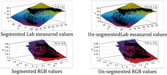
Figure 14. The relationship between segmented and un-segmented measured values of pattern (E).

Figure 15. The relationship between segmented and un-segmented measured values of (F).
(a)  (b)
(b)
Table 1. Normalized f(x, y) of mean, standard deviation and R2 and root mean square error of segmented measured printed color patterns.
objects that are not visible, creating better image information retrieval of image and as well distinguishing the region of interest (ROI) in the image for better
(a) (b)
Table 2. Normalized f(x, y) of mean, standard deviation and R2 and root mean square error of un-segmented measured printed color patterns.
color evaluation. The segmented patterns unlike un-segmented patterns provide dimensionality more adaptable to mathematical transformation that attempt to correct systematic errors which also helps to make the processing faster in this study.
The method used in this work was based on linear model that converts RGB ? L*a*b* color space. The results of this study showed that digital image processing XYZ techniques: image segmentation, employed prior to color measurement transformation help in manipulation of the digital images by observing the objects that are not visible, creating better image information retrieval of image and as well distinguishing the region of interest (ROI) in the image for better color evaluation. The segmented patterns unlike un-segmented patterns provide dimensionality more adaptable to mathematical transformation that attempt to correct systematic errors which also helps to make the processing faster in this study.
The Lab coordinates describes channel L* to be equal to 0 and L* equal to 100 indicating black and lightness respectively. Color channel a* negative (−a*) and positive (+a*) indicate green and magenta in the range of −128 and +127 respectively. The position yellow; +127 indicates b* positive (+b*) values while blue; −128 shows b* negative (−b*) values. The feasible range of channels a* and b* coordinates are independent of the color space that have been converted due to the transformation of X and Y which originate from RGB color space indicating the red-green and yellow-blue which appear to be opposite channels computed as dissimilarities of lightness transformations of patterns [23] .
CIELAB is chromatic color space values that imitate nonlinear response to the human eye [24] . Consequently, it was noted that the uniform variations of L*a*b* color space components relatively correspond to the uniform variations in perceived colors from all the segmented measured values. Hence, this study reveals that segmented and un-segmented values of L*, a* and b* were within range even though un-segmented measured patterns registered more RMSE than segmented measured patterns. This assertion proves the effectiveness of mathematical color transformation employed in measuring printed fabric patterns in this study. Absolutely, uniform perceptual transformations between any two colors in L*a*b* color space is estimated by considering each color as a point in a three dimensional space.
4. Conclusions
In this study, two all-purpose computer vision systems namely: image segmentation based on mean shift algorithm and L*a*b* color space transformation from RGB unit were employed for selected digital printed fabric patterns. Vital information extracted from original printed patterns using mean shift algorithm and then authenticated mathematically by RGB to XYZ to L*a*b*. Comprehensive results of segmented measured values presented compared to un-segmented measured values show that the method adopted is able to effectively validate homogeneity and uniformity in colors of printed fabric.
For quality inspection control, it is necessary to have assessment of production parameters including color of printed fabric aiming at producing same or similar product. CIELAB color space needs to be evaluated to determine the perceptual uniformity between sample and original since it is authenticated to correspond to equal color differences perceived by humans. This could be a desirable approach for successful market due to the fact that audience perceptions and reactions are paramount to the growth of textiles industries.
Future research will be focused on other mathematical transformations and compared to digital devices to determine appropriate and efficient method of measuring segmented printed fabric color patterns, thus minimizing the root mean square error with little or no human interaction
Acknowledgements
The authors acknowledge the financial support of Fundamental Research Funds for the Central Universities (JUSRP 51631A).
Conflicts of Interest
The authors declare no conflicts of interest regarding the publication of this paper.
Cite this paper
Kumah, C., Zhang, N., Raji, R.K. and Pan, R. (2019) Color Measurement of Segmented Printed Fabric Patterns in Lab Color Space from RGB Digital Images. Journal of Textile Science and Technology, 5, 1-18. https://doi.org/10.4236/jtst.2019.51001
References
- 1. Matusiak, M., Walawska, A. and Sybilska, W. (2017) Comparison of Spectrophotometric and Digieye Colour Measurements of Woven Fabrics. Journal of Textile & Apparel/Tekstil ve Konfeksiyon, 27, 53-59. http://dergipark.gov.tr/download/article-file/293787
- 2. Fan, J. and Hunter, L. (2009) Engineering Apparel Fabrics and Garments. In: Grosicki, Z., Ed., Engineering Apparel Fabrics and Garments, Woodhead Publishing Limited, Oxford, Cambridge, New Delhi, p. 416.
- 3. Lau, L.N. (2012) Colour Matching System for Colour Approval of Multi-Component Apparel. The Hong Kong Polytechnic University, Hong Kong. http://hdl.handle.net/10397/5537
- 4. Leon, K., Mery, D., Pedreschi, F. and Leon, J. (2006) Color Measurement in L*a*b* Units from RGB Digital Images. Food Research International, 39, 1084-1091. https://doi.org/10.1016/j.foodres.2006.03.006
- 5. Lau, L., et al. (2011) Study of the Correlation between Solid Colors Measured by Spectrophotometer and DigiEye. The First International Conference on Interdisciplinary Research and Development, Bangkok, 31 May-1 June 2011, 3.1-3.6.
- 6. Xu, B. and Lin, S. (2002) Automatic Color Identification in Printed Fabrics by a Neural-Fuzzy System. AATCC Review, 2, No. 9.
- 7. Xu, B. and Bel, P. (2009) Evaluation of Color Alterations on Fabrics by Image Analysis. AATCC Review, 9, No. 10.
- 8. Luo, L., Shen, H.L., Shao, S.J. and Xin, J.H. (2015) A Multispectral Imaging Approach to Colour Measurement and Colour Matching of Single Yarns without Winding. Coloration Technology, 131, 342-351. https://doi.org/10.1111/cote.12162
- 9. Milić, N., Novaković, D. and Kašiković, N. (2011) Measurement Uncertainty in Colour Characterization of Printed Textile Materials. Journal of Graphic Engineering and Design, 2, p. 2. https://www.researchgate.net/publication/281460343_Measurement_uncertainty_in_colour_characterization_of_printed_textile_materials
- 10. Kašiković, N., Dragoljub, N., Igor, K. and Gojko, V. (2015) Colour Fastness of Multilayer Printed Textile Materials to Artificial Light Exposure. Acta Polytechnica Hungarica, 12, No. 1.
- 11. Bovik, A.C. (2010) Handbook of Image and Video Processing. Academic Press, Massachusetts.
- 12. Johnson, E. (2010) Mean Shift Segmentation. Advanced Team Project (ATP). http://cmp.felk.cvut.cz/cmp/courses/33DZOzima2007/slidy/meanShiftSeg
- 13. Comaniciu, D. and Meer, P. (2002) Mean Shift: A Robust Approach toward Feature Space Analysis. IEEE Transactions on Pattern Analysis and Machine Intelligence, 24, 603-619. https://doi.org/10.1109/34.1000236
- 14. Ibraheem, N.A., et al. (2012) Understanding Color Models: A Review. ARPN Journal of Science and Technology, 2, 265-275. http://www.researchgate.net/publication/266462481_Understanding_Color_Models_A_Review
- 15. Reinhard, E., Adhikhmin, M., Gooch, B. and Shirley, P. (2001) Color Transfer between Images. IEEE Computer Graphics and Applications, 21, 34-41. http://www.cs.tau.ac.il/~turkel/imagepapers/ColorTransfer https://doi.org/10.1109/38.946629
- 16. Tarlak, F., Ozdemir, M. and Melikoglu, M. (2016) Computer Vision System Approach in Colour Measurements of Foods: Part II. Validation of Methodology with Real Foods. Food Science and Technology, 36, 499-504. https://doi.org/10.1590/1678-457X.02616
- 17. Defining and Communicating Color: The CIELAB System 2013. https://www.sappi.com
- 18. Barbin, D.F., et al. (2016) Digital Image Analyses as an Alternative Tool for Chicken Quality Assessment. Biosystems Engineering, 144, 85-93. https://doi.org/10.1016/j.biosystemseng.2016.01.015
- 19. Gonzalez, R.C. and Woods, R.E. (2002) Digital Image Processing, Second Edition, Publishing House of Electronics Industry, Beijing, 455.
- 20. Tekalp, A.M. (2015) Digital Video Processing. 2nd Edition, Prentice Hall Press, Upper Saddle River.
- 21. Zaitoun, N.M. and Aqel, M.J. (2015) Survey on Image Segmentation Techniques. Procedia Computer Science, 65, 797-806.
https://doi.org/10.1016/j.procs.2015.09.027
http://www.sciencedirect.com/science/article/pii/S1877050915028574 - 22. Rathore, V.S., Kumar, M.S. and Verma, A. (2012) Colour Based Image Segmentation Using L* a* b* Colour Space Based on Genetic Algorithm. International Journal of Emerging Technology and Advanced Engineering, 2, 156-162. https://pdfs.semanticscholar.org/20b3/8ef4bad12fa6901df375a39e8b853c825218.pdf
- 23. Baldevbhai, P.J. and Anand, R. (2012) Color Image Segmentation for Medical Images Using L* a* b* Color Space. IOSR Journal of Electronics and Communication Engineering, 1, 24-45. https://doi.org/10.9790/2834-0122445
- 24. Fdhal, N., Kyan, M., Dimitri, A. and Sharma, A. (2009) Color Space Transformation from RGB to CIELAB Using Neural Networks. In: Pacific-Rim Conference on Multimedia, Springer, Berlin, 1011-1017. https://doi.org/10.1007/978-3-642-10467-1_97