Open Journal of Civil Engineering
Vol.3 No.1(2013), Article ID:29453,6 pages DOI:10.4236/ojce.2013.31001
Comparison between Composite Column Using Limestone and Basalt Concrete
1Department of Civil Engineering, Tafila Technical University, Tafila, Jordan
2University of Bologna, Bologna, Italy
Email: *albaijath@yahoo.com
Received November 13, 2012; revised December 10, 2012; accepted December 26, 2012
Keywords: Composite Column; Basalt Mix; Jordan
ABSTRACT
This research is conducted to study the experimental behavior of composite steel-concrete columns with basalt additives. Various percentages of basalt are added to the concrete mixes to investigate its effect on the total axial compressive capacity of the columns. Expected failure scenarios of the columns are: concrete compressive failure, buckling of steel section, and de-bonding between steel and concrete sections. A conventional limestone composite column was used as base mix. The results of the study indicate a significant improvement in structural behavior and strength of the columns by increasing the percentage of basalt content.
1. Introduction
Composite columns using limestone were widely used from early 1900s. However, none or very little research conducted for using basalt in composite columns. Viest in his 1960 review of research, notes that the important factor in composite actions is the bond between concrete and steel [1].
The steel-concrete composite column is a new composite member that can achieve constructability and economy by filling the empty space in the steel H-flange with concrete. Composite columns are constructed with rolled or built-up steel section. The resulting members are able to support significantly higher loads than reinforced concrete columns of the same sizes.
A structural member composed of two or more dissimilar materials joined together (to act as a unit in which the resulting system) is stronger than the sum of its parts. An example in civil structures is the steel-concrete composite column in which a steel wide-flange shape (I or W shape) is filled with various percentages of basalt to be compared with base limestone concrete mix. Basalt is hard, dense volcanic igneous rock that can be found in most countries across the world.
Basaltic rocks are available in Jordan in many places especially in the Northeastern volcanic Plateau in Harrat Ash Shaam, Asi and Shalabi, 2005 [2]. Basalt is used in many countries especially in highway and airfields pavement construction (Rodsenbaum and Skene, 1995). Jordan has also a number of quarries and crushers equipped with advanced technologies and machinery to crush basaltic rocks into construction size aggregates. In conventional concrete mixes used in the construction industry in Jordan; it is customary to use limestone aggregates which are also available in great abundance. Basaltic rock aggregates are similar to limestone aggregates in many aspects [3]. Table 1 shows the key properties of limestone and basalt aggregates in Jordan. The basalt aggregates are higher in specific gravity, and lower in absorption and abrasion loss values [3]. Based on this comparison, it is clearly obvious that basalt is likely to be more suitable than limestone for use in concrete mixes and this research will investigate this matter. In order to accomplish this objective, the researcher has devised an elaborate laboratory testing program that included conventional limestone mixes with zero%, 25%, 50%, 75% and 100% basalt. For the purpose of comparison, samples from each mix were then tested in the laboratory to determine key mix properties.
2. Experimental Program
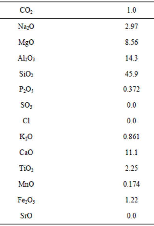
The basalt aggregates used in this research were tested for chemical composition at the Department of Chemistry of the University of Jordan by using the X-Ray Fluorescence (XRF) test. The results of this test are summarized in Table 2. Also the mechanical properties of the basalt aggregate were conducted as shown in Table 3. The results of three specimens for each group were averaged
Table 1. Key properties of limestone and basalt aggregates used in Jordan (Courtesy of Dr. Zuhair Samarah and engineer Jamil Wrekat) [4].
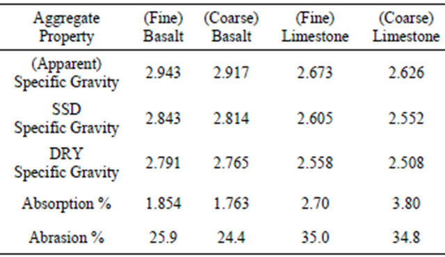
Table 2. Chemical composition of basaltic aggregates as determined By X-Ray fluorescence test (X.R.S) % [4].
because their graphs are almost identical. The average deflections and strains represent one curve for each group of three specimens.
It is obvious from Table 3 that the strength of the cubes increases gradually as the percentage of basalt increases. The dimensions of the cube were 150 mm × 150 mm × 150 mm.
The first author conducted laboratory tests on 18 columns. The chart in Figure 1 shows the diagram of experimental program in this investigation. Five design mixes were used including limestone as base mix, with 25%, 50%, 75%, and 100% basalt. Three steel columns were used as reference. Figure 1 shows percentages of basalt in the different mixes of composite columns. The cross section of all specimens was 80 mm × 160 mm, for the width and depth and their height was 1400 mm, as shown in Figure 2.
The geometry of the steel section was shown in Figure 2.
3. Laboratory Procedure
Five mixes were prepared; namely limestone (0% basalt as base mix), 25%, 50%, 75%, and 100% basalt. The composition of each mix is presented in Table 4 [4]. The
Table 3. Compressive strength (kN) versus percentage of basalt.
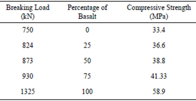
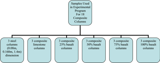
Figure 1. The chart of the experimental work used in this study.
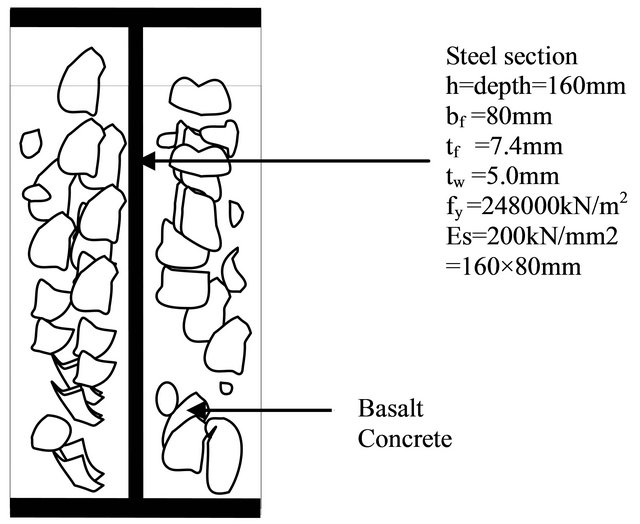
Figure 2. Typical composite cross section of the column. L = 1400 mm.
water cement ratio was 0.7 including 0.25 for hydration, and the cement was 350 kg per cubic meter of concrete.
4. Results
The center line of the composite columns were coincided with the centerline of the testing machine carefully to avoid any eccentricity and the two ends of the column were attached to the ground and to the testing machine by using rectangular steel (to avoid any horizontal movement). The mid height of the columns were marked at both sides and the dial gage (transducers) was attached to the level of marked line to measure the deflection of concentric composite columns. Similarly the other side of the column was marked, and two demic gages (transducers) (ASTM426 strain gage and BS1881:206) were attached to the column 10 cm above and below the center line. In this case the vertical distance between the two gages were 20 cm. The strain and deflection were taken from the two gages directly by using correction factor for the testing machine for both strain and deflection. The loads were applied gradually to the specimens till failure.
There was no cyclic loading applied.
After loading the column and prior to initiation of buckling, it was noted that the specimen starts to have hair horizontal cracks (parallel to the marked line). The cracks occurred in the tension region. No cracks noticed in the compression region. The load was applied gradually to the specimen and the readings were taken at various stages of loading. For this test only ascending loading was used (no cyclic loading). Out-of-plane deformation (buckling) was measured using only one dial gage since the column is short and the width is also small. The set-up of the specimen is shown in Figures 3 and 4 with strain and deflection gages attached. The strains versus loads are shown for various percentage of basalt in Table 5 and Figure 5. As the load increases; the strain of the column increases. Each curve represents the average value for three specimens for the same load and the same percentage of basalt. The standard deviations were 0.026 and 0.076 for both deflection and strain respectively.
1) The three steel and limestone composite columns were taken in this experimental program as a base specimen. It was noticed that, compared with steel columns for 500 kN load, the strain and buckling decreased by 13.5% and 60%, respectively for 0% basalt. The results are shown in Tables 5 and 6.
2) Now the composite columns are 25% basalt and 75% limestone, the test results show significant decrease (38% and 35%) for the strain and buckling at 600 kN load as illustrated in Tables 5 and 6.
3) In this case the three composite columns are 50% basalt and 50% limestone each, and the average results are shown in Table 6 and in Figure 6 for the deflection and the results were presented in Table 5 and Figure 5 for the strain. The strain and buckling decreased by 21.8% and 16%, respectively for the 700 kN load. Load carrying capacity increases as the percentage of basalt in composite section increases (Table 7 and Figure 7).
Table 4. Percentage of basalt in composite section in the different mixes.
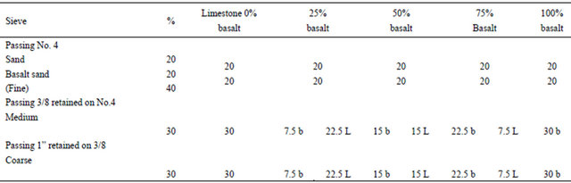
b = basalt, L = limestone.

Figure 3. Composite basalt column under concentric load with strain and buckling (deflection) gages (transducers).
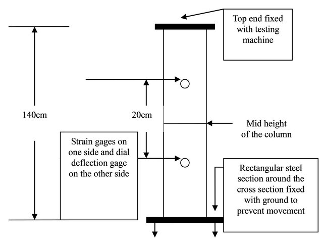
Figure 4. Location of the strain gages on one side of the column for strain.
Table 5. Load versus strain x10E−4 for various percentages of basalt.


Figure 5. Load (kN) versus strain (1 × 10E−4).
Table 6. Load (kN) versus deflection (mm) for various percentages of basalt.
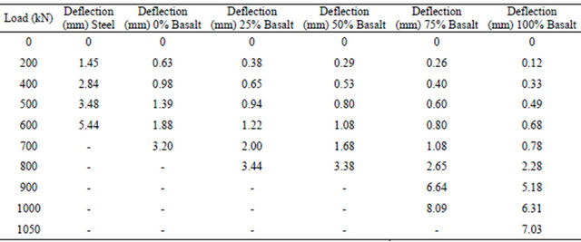
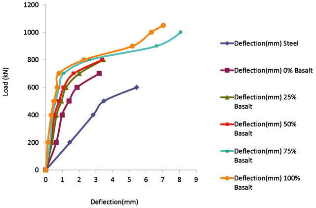
Figure 6. Load kN versus deflection (mm).
Table 7. Failure load versus percentage of basalt in composite column.

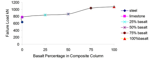
Figure 7. Failure load kN versus percentage if basalt in composite columa.
The strain gages were attached to the specimen as shown in Figure 4.
4) Three composite columns were tested with 75% basalt and 25% limestone. The average tests results for deflection are shown in Table 6 and in Figure 6. The strain and buckling averages were decreased by 20.5% and 40.1% respectively. The capacity of the composite basalt columns increased by 20.6% as basalt in the mix increased from 50% to 75%.
5) In the case of 100% basalt composite column, deflection decreased by 22% (Table 6 and Figure 6), and strain also decreased by 55.3% at load 1000 kN (Table 5 and Figure 5). All the deflections results for six groups for various percentages of basalt are illustrated in Table 6 and Figure 6.
6) The results (Table 7 and Figure 7) showed significant increase in failure load as the percentage of basalt increased from 25%, 50%, 75% to 100% in composite column of about 9%, 12.5%, 34.2% and 39.4% respectively relative to the base mix (limestone). The failure load of the composite with 75% limestone and 25% basalt increased by 21% and 32% compared with steel section only.
7) Significant reduction in strain (54%, 65% and 71%, at 200, 400 and 700 kN respectively) took place as the composite column changed from limestone to 100% basalt as in Table 5 and Figure 5.
8) Buckling (deflection) of the composite basalt columns decreased significantly (about 64%) compared with limestone composite columns. This reduction indicates that basalt composite columns are much stronger and more durable than those of limestone (Table 6 and Figure 6).
5. Analysis of the Results
The key properties investigated in this research project included:
1) Lateral buckling conducted under axial concentrated load, three steel columns (0.08 m, 0.16 m, 1.4 m) and three composite columns for each mix percentage total of 15 columns.
2) Strain versus load.
3) Failure load for various percentages of basalt.
As the load increased gradually from 200 kN to 650 kN, the deflection at various percentages shows no significant difference, but when the load increased from 650 kN to 1050 kN, the deflection increased for the same percentage of basalt. At the same loading, the deflection decreases as the percentage of basalt increases. This indicates that the load bearing capacity of the specimens increased as the percentage of basalt increased [5] (Table 6 and Figure 6). The experimental results show that the deflection of the steel column at 500 kN decrease by 60% (compared with limestone composite column), while decreased by 12%, 45%, 55%, and 69% as the percentage of basalt increased (from 25%, 50%, 75% and 100%) respectively. The strains decreased by 40.7% when comparing steel column with limestone composite column. However, as the percentage of basalt in the composite column was increased by 25%, 50%, 75% and 100%, respectively for 600 kN, the strains were correspondingly decreased by 39%, 42%, 45%, and 71%. The failure loads increased by 17.6% when comparing steel beam with composite limestone. By increasing the percentage of basalt by 25% at each stage, the failure load increased by 8.2%, 11%, 25% and 28%.
6. Acknowledgements
The author would like to thank the Tafilah Technical University for the financial support of this research project.
7. Conclusions and Recommendation for Further Research
It was noticed from the experimental work that the composite basalt column behaved better than limestone composite column. This improvement is relevant only to concentric axial compressive load conditions. Thus using composite basalt column rather than limestone column is highly recommended. To avoid any slip problems between steel and basalt concrete, the authors recommends future research on using mechanical stud connector to resist shear which may develop during bending. The stud should be attached to the web of the column to keep the bond in the composite section.
REFERENCES
- I. M. Viest, “Review of Research on Composite SteelConcrete Construction,” Journal of the Structural Division, ASCE, Vol. 86, No. ST6, 1960, pp. 1-21; Also Transactions on ASCE, Partii, Vol. 126, 1961, pp. 1101-1123.
- I. M. Asi, “Evaluating Skid Resistance of Different Asphalt Concrete Mixes,” Building and Environment Journal, 2005, in press.
- Ministry of Public Works and Housing, “Specifications for Highway and Bridge Construction, Vol. II,” Ministry of Public Works and Housing of Hashemite Kingdom of Jordan, 1991.
- H. M. O. Al-Baijat, “The Use of Basalt Aggregates in Concrete Mixes in Jordan,” Jordan Journal of Civil Engineering, Vol. 2, No. 1, 2008, pp. 63-70.
[6] NOTES
[7]
[8] *Corresponding author.
[9]