Modern Mechanical Engineering
Vol.09 No.02(2019), Article ID:92318,8 pages
10.4236/mme.2019.92005
Design and Strength Verification of LNG Cargo Enclosure System FSP Type
Zeng Ji1, Yuan Bo1*, Feng Qi2, Chen Yan2
1Shanghai Maritime University Offshore Engineering Technology Research Center, Shanghai, China
2Shanghai Honghua Ocean Oil & Gas Equipment Co., Ltd., Shanghai, China

Copyright © 2019 by author(s) and Scientific Research Publishing Inc.
This work is licensed under the Creative Commons Attribution International License (CC BY 4.0).
http://creativecommons.org/licenses/by/4.0/


Received: April 7, 2019; Accepted: May 6, 2019; Published: May 9, 2019
ABSTRACT
The demand for natural gas in the world is increasing day by day. The efficient and flexible LNG becomes the preferred method for natural gas storage and transportation and has gradually entered people’s daily life. The enclosure system is the key core of LNG transport and storage vessels for storage of LNG at −163˚C for isolation and thermal insulation. A new type of flat half-film prismatic LNG enclosure system has been developed for the shortcomings of the existing LNG cargo enclosure system. Through the breakthrough and mastery of key core technologies such as the overall layout and integration of the system, anti-leakage technology, liquid tank fixing technology, and large-scale friction stir welding (P-FSW) flat-line pipeline development technology, we’ll strive to fill the gap in the intelligent construction technology of large aluminum alloy tanks in China. The tank was subjected to water vapor test and numerical simulation. The results show that the structural strength of the FSP-LNG tank meets the strength check standard of IGC Code.
Keywords:
LNG Tank, Water Vapor Test, Numerical Simulation, Strength

1. Introduction
The physical characteristics of natural gas make the cargo enclosure system the core of the design and construction of LNG ships, which has been monopolized by foreign countries. The LNG storage devices of the current LNG carriers mainly include the MOSS spherical tank type, the GTT film type and the IHI SPB diamond type. In that, the film type LNG vessel has an absolute advantage, and the patents of the film type LNG cargo containment system (NO96, CS-1 and MK-III) have been monopolized by foreign companies, both the enclosure systems of NO96 and MK-III film-type LNG cargo occupy almost all of the LNG ship market under construction.
Under the background of fierce international environment and competition in the LNG vessel market, a new type of flat half-film prismatic LNG enclosure system has been developed. Among them, the flat plate means that the inner tank is welded by a regular aluminum or steel flat plate, and the semi-film means that the secondary shielding of the retaining system only needs to be partially wrapped but not completely wrapping, and the prism means the overall shape of the enclosure system is a regular prismatic polygonal cylinder structure. The enclosure system has the advantages of larger volume ratio, lighter weight and less impact on the hull structure. Through the breakthrough and mastery of key core technologies such as the overall layout and integration of the system, anti-leakage technology, liquid tank fixing technology, and large-scale friction stir welding (P-FSW) flat-line pipeline development technology, we will strive to fill the domestic large-scale aluminum alloy tanks, break the situation that LNG cargo enclosure system monopolized by international giants, realize the modular intelligent intelligence of LNG cargo enclosure system with independent intellectual property rights, and promote the development and application of key technologies, materials and equipment.
2. The Design Features of FSP Type LNG Cargo Enclosure System
In view of the shortcomings of the existing LNG cargo containment system, a new FSP-LNG (Flat-Panel, Semi-Membrane, Prismatic-Shaped) containment system was developed. The flat plate means that the inner tank is made of aluminum with a regular shape. Or steel flat plate welded, semi-film means that the secondary shielding of the retaining system only needs to be partially wrapped without completely wrapping the inner tank. The prismatic shape means that the overall shape of the retaining system is a regular prism-like polygon. The column structure has the advantages of larger volume ratio, lighter weight and less influence on the hull structure.
2.1. The Prevention System of LNG Storage Tank Leakage
At present, MOSS type storage tank is the most similar one of marine LNG storage tank and FSP-LNG storage tank. The tank is horizontally decomposed into a plurality of ring belts during the construction; each ring belt is composed of a plurality of sheets. The sheet body is firstly manufactured, then sheet body is formed into a loop belt, and finally the loop belt will be assembled into a sphere body. The outer layer of the spherical tank type cargo tank is covered by a heat insulating structure. A drip tray is placed under the bottom of the spherical tank type cargo tank to form a reduced secondary wall to accommodate the potentially leaked LNG. The drip tray is arranged in the inside bottom of the hull, and the insulating layer of the supporting structure isolates the drip tray from the inside bottom of the hull. The cd material of drip tray material is stainless steel or the same material as the spherical tank type cargo tank, generally 5083-O aluminum alloy. The top of the drip tray is made up of flanged panels, and a baffle is placed inside to prevent the accumulation of liquid due to the roll and trim of the hull. When installing the external insulation layer of the MOSS type storage tank, there should be a gap of several millimeters between the insulation layer and the outer surface of the storage tank. During the installation process, it is necessary to ensure that the time and cost of the gap between the insulation layer and the outer surface of the tank is relatively high, and the process is quite complicated. Moreover, when the leakage of the outer surface of the tank happens, the leaked LNG flows along the gap between the outer surface of the tank and the heat insulation layer to the secondary shield due to the gravity of the liquid itself [1] . This kind of treatment method would cause low efficiency of LNG collection for leakage, and the leakage of LNG may vaporize when flowing between the outer surface of the tank and the thermal insulation layer, which will result in damage to the thermal insulation layer.
The leak handling structure has been developed for FSP type LNG storage tank. A leak guiding device is installed at the weld of the outer surface of the LNG metal storage tank; it’s used to guide the LNG that may lead to the LNG collection area, which is at the bottom of the tank. A semi-circular leakage guide tube is covered by welding or bonding along all the weld seams on the outer surface of the outer casing of the LNG storage tank, the heat insulation layer completely encloses the tank body and the leakage guide tube, then wraps the skin on the outside and inserts a gas ventilating device on the heat insulation layer on the top of the tank body. The venting device is in communication with the leakage guiding tube, and the leakage device is located at the side of the bottom of the tank body. The leakage device communicates with the leakage tube through the insulation layer. The technical solution has the advantages of simple structure, easy operation and low cost. As shown in Figure 1, schematic diagram of prevention system of LNG storage tank leakage is below.
2.2. The Fixing System of Six-Freedom-Degree Tank
The inner tank of the LNG enclosure system is a flexible tank. The inner tank has only the stiffener supporting the outer shell, without any additional structures. Compared with the existing SPB type LNG enclosure system, the inner tank is simpler in structure, requires less man-hours, lighter in weight and with a larger internal volume ratio.
The existing SPB type LNG retaining system only limits the retaining system through the wedge at the top, and it is easy to form stress concentration on the corresponding hull part in terrible sea conditions. The FSP-LNG enclosure system shown in Figure 2 is a retaining system that is limited and fixed by universal support evenly distributed around the inner tank. The universal support
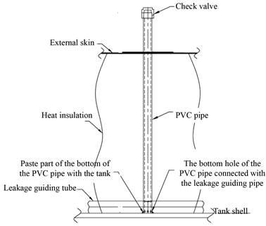
Figure 1. The form of anti-leakage system.

Figure 2. The fixing system of six-freedom-degree tank.
limits longitudinal movement, lateral movement and rotation of 5 degrees of freedom around its own axis, while the vertical degree of freedom is resisted by its own gravity, so that it can fully resist the movement of six degrees of freedom and play an important role in limiting positioning. This kind of device can fully absorb the impact of liquid sloshing. The load distribution is more uniform and has less impact on the structure of the vessel.
3. Water Vapor Test
At room temperature, the structural strength and deformation of the FSP-LNG storage tank under simulated loading were detected by injecting water and compressed air into the tanks in horizontal and vertical conditions and holding them separately.
3.1. Test Procedure
The water vapor test of LNG storage tank would be carried out under the condition that the temperature difference does not exceed 5˚C and the ambient room temperature shall not exceed 45˚C.
There are following test procedures shown in Figure 3 after attaching the strain gauge and cleaning the inside of the tank.
The points of the test are as below:
1) Select wood or rubber for temperature isolation and cushion for the contact area of tank and surface;
2) Remote reading and recording functions must be available in Pressure sensors and strain gauges. The pressure sensor has a range of 0 - 0.1 Mpa and an accuracy level of 0.5;
3) It’s required to use a hose to fill the tank with water, avoiding the water flow directly flushing the tank wall;
4) During the pressure holding for 4 h, the pressure drop should be kept within ±0.007 Mpa.
3.2. Test Result
Table 1 shows the strength check criteria for the LNG ship cargo tank structure in the IGC CODE.
The test data of 10 monitoring points are processed in Table 2.
It can be seen that the test results of the water vapor test meet the relevant requirements of the IGC Code. From the stress results, FSP-LNG storage tank can work normally under simulated loading conditions.
4. Numerical Verification
4.1. Model Processing
The overall model is modeled using a board unit (Shell 181), the unit is mm. The range includes the tank body and the partial structure of the secondary screen wall in direct contact with it. The Targe 170 unit is set on the contact surface between the secondary screen wall and the tank bottom plate to simulate the contact between the primary and secondary screen walls which cannot penetrate each other but can transmit pressure and friction [2] .
The tank material is 5083-O aluminum alloy, which has good corrosion resistance and weldability [3] . Its density is 2660 kg/m3, Young’s modulus is 71,000 Mpa, Poisson’s ratio is 0.33. The processed model is shown in Figure 4.
4.2. Calculation Condition
The following four conditions are mainly calculated for the FSP-LNG storage tank [4] :
G1―Tank empty, only by gravity, and ignore other initial loads;
G2―Tank full (LNG is charged to 98%), the internal temperature of the tank is −163˚C, the pressure is 0.07 Mpa, and it is affected by gravity;
G3―The tank is loaded at the lowest level and the LNG liquid level is 0.45 m, the temperature of the top plate is set to −151˚C, the internal temperature is −163˚C, the pressure is 0.07 MPa and it is subjected to gravity;

Figure 3. Procedure of water vapor test.

Figure 4. FSP-LNG FEM model of the tank.

Table 1. Allowable stresses (IGC Code).
Table 2. Water vapor test result.
G4―The tank is loaded at the lowest level, the LNG liquid level is 0.45 m, the top plate temperature is set to −151˚C, the internal temperature is −163˚C, and the internal pressure is 0.0185 Mpa, simulating the state when the tank is kept vacuum after loading.
4.3. Numerical Simulation Result and Analysis
Shown as Table 3, the calculation results of maximum stress and maximum displacement under various working conditions are given. According to the standard of BV classification society, the calibration stress of 5083-O aluminum alloy is 125 Mpa [5] .
Table 3. Result of numerical simulation calculation.
It can be seen from the calculation data that the FSP-LNG storage tank can work normally under the four calculation conditions, and the highest stress still has a 60% margin.
5. Conclusions
This paper systematically analyzes the FSP-LNG cargo enclosure device and obtains the design experience and conclusions as below:
1) The designed anti-leakage device is easy to install and disassemble, and effectively avoids leakage of the internal LNG;
2) The six degrees of freedom fixing device prevents the tank from sloshing in the cabin to some extent;
3) The structural reliability of FSP-LNG storage tank under simulated conditions was verified by water vapor test and numerical simulation.
Acknowledgements
I would like to take this opportunity to thank technology staff from Shanghai Honghua Ocean Oil & Gas Equipment Co., Ltd., who have offered invaluable assistance in the preparation of the dissertation.
Conflicts of Interest
The authors declare no conflicts of interest regarding the publication of this paper.
Cite this paper
Ji, Z., Bo, Y., Qi, F. and Yan, C. (2019) Design and Strength Verification of LNG Cargo Enclosure System FSP Type. Modern Mechanical Engineering, 9, 49-56. https://doi.org/10.4236/mme.2019.92005
References
- 1. Gao, J.F., Yuan, J.W., Xu, Y.X. and Qiu, Y.Q. (2018) Research on Leakage Accident of Film LNG Ship. Naval Architecture and Ocean Engineering, 2, 74-78.
- 2. Guo, W.J. (2010) Structural Analysis of Fil Type LNG Ship Enclosure System under Sloshing Load. Dalian University of Technology, Dalian, China.
- 3. Wang, Q.F., Han, C.Q. and Li, Y.Z. (2013) Research of the Strength Criterion of the Scaffolding Plate Form of the LNG Carrier. Journal of Jiangsu University of Science and Technology (Natural Science Edition), 1, 5-9.
- 4. He, X.C., Yang, J.G. and Zhou, R.P. (2015) Research on Fatigue Strength Analysis of Marine LNG Tanks. Ship Engineering, 5, 19-23.
- 5. Liu, D.-J., Cao, J.-L., Jin, Q.-Z. and Cheng, K. (2015) Numerical Simulation Analysis for Swash Plate of LNG Tank onboard Based on CEL. Ship and Ocean Engineering, 4, 162-166.