Modern Mechanical Engineering
Vol.05 No.01(2015), Article ID:53766,8 pages
10.4236/mme.2015.51001
Stress Analysis of Thin-Walled Pressure Vessels
Ahmed Ibrahim*, Yeong Ryu, Mir Saidpour
Mechanical Engineering Technology, Farmingdale State College, Farmingdale, New York, USA
Email: *ahmed.ibrahim@farmingdale.edu, yeong.ryu@farmingdale.edu, mir.saidpour@farmingdale.edu
Copyright © 2015 by authors and Scientific Research Publishing Inc.
This work is licensed under the Creative Commons Attribution International License (CC BY).
http://creativecommons.org/licenses/by/4.0/


Received 15 January 2015; accepted 1 February 2015; published 3 February 2015
ABSTRACT
This paper discusses the stresses developed in a thin-walled pressure vessels. Pressure vessels (cylindrical or spherical) are designed to hold gases or liquids at a pressure substantially higher than the ambient pressure. Equations of static equilibrium along with the free body diagrams will be used to determine the normal stresses  in the circumferential or hoop direction and
  in the longitudinal or axial direction. A case study of internal pressure developed in a soda can was determined by measuring the elastic strains of the surface of the soda can through strain gages attached to the can and connected to Strain indicator Vishay model 3800.
Keywords:
Stress Analysis, Thin-Walled Pressure Vessel

1. Introduction
Pressure vessels are compressed gas storage tanks designed to hold gases or liquids at a pressure substantially different from the ambient pressure. They have a variety of applications in industry, including in oil refineries, nuclear reactors, gas reservoirs, etc. An aircraft fuselage, a gas cylinder and a soda can, all are pressure vessels which must be designed to meet very specific requirements of integrity. The human arteries maintain pressure in the circulatory system much like a balloon maintains pressure on the air within it. The arteries therefore act as pressure vessels by maintaining pressure. Pressure vessels can be any shape, but shapes made of sections of spheres and cylinders are usually employed. A common design is a cylinder with end caps called heads. Head shapes are frequently hemispherical.
Cracked or damaged vessels can result in leakage or rupture failures. Potential health and safety hazards of leaking vessels include poisonings, suffocations, fires, and explosion hazards. Rupture failures can be much more catastrophic and can cause considerable damage to life and property. The safe design, installation, operation, and maintenance of pressure vessels are in accordance with codes such as American Society of Mechanical Engineers (ASME) boiler and pressure vessel code [1] . Therefore, great emphasis should be placed on analytical and experimental methods for determining their operating stresses.
Spherical Pressure Vessel, like the one shown in Figure 1, is preferred for storage of high pressure fluids. A spherical pressure vessel has approximately twice the strength of a cylindrical pressure vessel with the same wall thickness. A sphere is a very strong structure. The distribution of stresses on the sphere’s surfaces, both internally and externally are equal. Spheres however, are much more costly to manufacture than cylindrical vessels. A spherical storage has a smaller surface area per unit volume than any other shape of vessel. This means, that the quantity of heat transferred from warmer surroundings to the liquid in the sphere, will be less than that for cylindrical storage vessels.
Pressure vessels are subjected to tensile forces within the walls of the container. The normal stress in the walls of the container is proportional to the pressure and radius of the vessel and inversely proportional to the thickness of the walls [2] [3] . As a general rule, pressure vessels are considered to be thin-walled when the ratio of radius r to wall thickness t is greater than 10 [4] . Pressure vessels fail when the stress state in the wall exceeds some failure criterion [5] [6] . Therefore pressure vessels are designed to have a thickness proportional to the radius of tank and the pressure of the tank and inversely proportional to the maximum allowed normal stress of the particular material used in the walls of the container. Thus, it is important to understand and quantify (analyze) stresses in pressure vessels. In this paper we will analyze the stresses in thin-walled pressure vessels (cylindrical & spherical shapes), like the one shown in Figure 1 & Figure 2. In addition, a case study of internal stresses developed in a soda can will be presented and discussed.

Figure 1. Japanese gas companies added a touch of character to giant spherical gas tanks.

Figure 2. Cylindrical pressure vessel in a chemical plant.
2. Thin-Walled-Cylindrical Pressure Vessel
A thin-walled circular tank AB subjected to internal pressure shown in Figure 3. A stress element with its faces parallel and perpendicular to the axis of the tank is shown on the wall of the tank. The normal stresses  and
and  acting on the side faces of this element. No shear stresses act on these faces because of the symmetry of the vessel and its loading. Therefore, the stresses
  and
and  are principal stresses. Because of their directions, the stress
  is called the circumferential stress or the hoop stress, and the stress
  is called the longitudinal stress or the axial stress. Each of these stresses can be calculated from static equilibrium equations.
Several assumptions have been made to derive the following equations for circumferential and longitudinal stresses:
1) Plane sections remain plane
2)  with
with  being uniform and constant
3) Material is linear-elastic, isotropic and homogeneous.
4) Stress distributions throughout the wall thickness will not vary
5) Weight of the fluid is considered negligible.
3. Circumferential Stress
To determine the circumferential stress , make three sections (cd and ef) perpendicular to the longitudinal axis and distance
  apart (Figure 3(a)); and a third cut in a vertical plane through the longitudinal axis of the tank. The resulting free body diagram is shown in Figure 3(b). Acting on the longitudinal cut (plane cefd) are the circumferential stresses
  and the internal pressure
 .
.
The circumferential stresses  acting in the wall of the vessel have a resultant equal to
 , where
  is the thickness of the wall. Also, the resultant force
  of the internal pressure is equal to
 , where
  is the inner radius of the cylinder. Hence, we have the following equation of equilibrium:

From the above equation, the circumferential stress in a pressurized cylinder can be found:
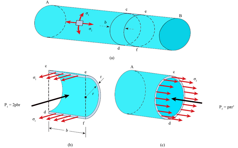
Figure 3. Stresses in a circular cylindrical presure vessel.
 (1)
(1)
If there exist an external pressure  and an internal pressure
 , the formula may be expressed as:
 (2)
(2)
4. Longitudinal Stress
The longitudinal stress  is obtained from the equilibrium of a free body diagram shown in Figure 3(c). The stresses
  acts longitudinally and have a resultant force equal to
 . The resultant force
  of the internal pressure is a force equal to
 . The equation of equilibrium for the free body diagram is

Solving the above equation for , lead to the following formula for the longitudinal stress in a cylindrical pressure vessel:
 (3)
(3)
If there exist an external pressure  and an internal pressure
 , the formula may be expressed as:
 (4)
(4)
Comparing Equations (1) and (3) we find that the circumferential stress in a cylindrical vessel is equal to twice the longitudinal stress:
 (5)
(5)
Due to this, cylindrical pressure vessels will split on the wall instead of being pulled apart like it would under an axial load.
5. Stresses at the Outer Surface
The principal stresses  and
and  at the outer surface of a cylindrical vessel are shown on the stress element of Figure 4(a). The element is in biaxial stress (stress in z direction is zero).
The maximum in-plane shear stresses occur on planes that are rotated 45˚ about the z axis:

The maximum out-of-plane shear stresses occur on planes that are rotated 45˚ about  and
and  axes, respectively:


Therefore, the maximum absolute shear stress is:
 (6)
(6)
Occurs on a plane rotated by 45˚ about the x-axis.
6. Stresses at the Inner Surface
The stress conditions at the inner surface of the wall of the vessel are shown in Figure 4(b). The principal stresses

Figure 4. Stresses in a circular cylindrical pressure vessel at (a) the outer surface, (b) the inner surface.
are:

The three maximum shear stresses, obtained by 45˚ rotations about the ,
,  , and
, and  axes, are
 (7)
(7)
 (8)
(8)
 (9)
(9)
When  is very large (thin walled), the term
  can be disregarded, and the equations are the same as the stresses at the outer.
7. Spherical Pressure Vessel
A similar approach can be used to derive an expression for an internally pressurized thin-wall spherical vessel. A spherical pressure vessel is just a special case of a cylindrical vessel.
To find  we cut the sphere into two hemispheres as shown in Figure 5. The free-body diagram gives the equilibrium condition
 , hence
 (10)
(10)
Any section that passes through the center of the sphere yields the same result. Comparing Equations (1), (3), and (10) yields that for the same ,
,  and
and  the spherical geometry is twice as efficient in terms of wall stress.
As shown in Figure 6, the internal pressure of the cylindrical vessel is resisted by the hoop stress in “arch action” whereas the axial stress does not contribute. In the spherical vessel the double curvature means that all stress directions around the pressure point contribute to resisting the pressure.

Figure 5. Stresses in a spherical pressure vessel.

Figure 6. (a) Spherical pressure vessel; (b) Cylindrical pressure vessel.
8. Case Study: Measuring Internal Pressure in a Soda Can Using Strain Gauges
The soda can is analyzed as a thin wall pressure vessel. In a thin wall pressure vessel, two stresses exist: the longitudinal stress  and the hoop stress
  (Figure 7). The longitudinal stress is a result of the internal pressure acting on the ends of the cylinder and stretching the length of the cylinder as shown in Figure 8. The hoop stress is the result of the radial action of the internal pressure that tends to increase the circumference of the can.
The pressure developed in a soda can be determined by measuring the elastic strains of the surface of the soda can. Internal pressure for a pressurized soda can be derived using basic Hooke’s law stress and strain relations that relate change in hoop and axial strains to internal pressure. Two strain gauges (Measurements Group-CEA series gages) was attached to the soda can (Figure 9) to measure the change in strains, as measured through the voltage across a calibrated Wheatstone bridge. M-bond 200 adhesive (Measurements Group, Inc) was used to glue the strain gages to the surface of the soda can.
The hoop stress for the thin walled cylinder can be calculated from Equation (1)
 where:
 ―internal pressure (psi)
D―mean diameter of cylinder (in.)
t―wall thickness (in.)
Similarly, the longitudinal stress cylinder wall can be calculated from Equation (3)

Equation (5) yields


Figure 7. Coca cola soda can.

Figure 8. Longitudinal stress distribution.

Figure 9. Strain gages attached to a soda can and strain indicator vishay model 3800.
Assuming that:
・ The material is homogeneous and isotropic,
・ The can is loaded only within its elastic range,
・ A biaxial state of stress exists in the can,
The internal stresses developed in the soda can are proportional to the elastic strains of the outside surface of the soda can as follow:
 (11)
(11)
 (12)
(12)
where:
 ―modulus of elasticity or Young’s modulus (psi)
 ―Poisson’s ratio
 ―hoop strain (in/in)
 ―longitudinal strain (in/in)
Using Equations (11) and (12) with Equation (5), and simplifying results in:
 (13)
(13)
 (14)
(14)
Thus the pressure can be calculated directly from the measured strains by substituting Equations (13) and (14) back into Equation (1) and (2) to get:
 (15)
(15)
 (16)
(16)
Once we have Equations (15) and (16), then the internal pressure in the can may be directly calculated from the measured longitudinal and hoop strains.
9. Internal Pressure Results
Measured Values
Can thickness: t = 0.004 in
Can diameter: D = 2.59 in
Young’s Modulus: E = 10 × 106 psi (assumed)
Poisson’s Ratio: 
The change in longitudinal and hoop strains were measured after the pressure was released from the cans. The results of the strains and corresponding pressures are shown in Table 1.
10. Conclusion
This paper presented a detailed stress analysis of the stresses developed in thin-walled pressure vessels (cylindrical & spherical). Then, a case study of a soda can that was analyzed as a thin wall pressure vessel was discussed. The elastic strains ( &
& ) of the external surface of the soda can was determined through strain gages attached to the can surface and connected to a strain indicator. The longitudinal stress, hoop stress, and the internal pressure were determined from equations of generalized Hooke’s law for stress and strain. Small varia-

Table 1. Elastic strains and corresponding internal pressures in a Soda can.
tions recorded in internal pressures calculated from the longitudinal strain  and the hoop strain
 .
.
References
- Rao, K. (2012) Companion Guide to the ASME Boiler and Pressure Vessel Code, Volume 1, Fourth Edition, ASME. http://dx.doi.org/10.1115/1.859865
- Gere, J. and Timoshenko, S. (1997) Mechanics of Materials. 4th Edition, PWS, 549. http://dx.doi.org/10.1007/978-1-4899-3124-5
- Moss, D. (2013) Pressure Vessel Design Manual. Elsevier. http://dx.doi.org/10.1016/b978-0-12-387000-1.10032-4
- Freyer, D. and Harvey, J. (1998) High Pressure Vessels. Springer, Berlin, 11. http://dx.doi.org/10.1007/978-1-4615-5989-4
- Annaratone, D. (2007) Pressure Vessel Design. Springer, Berlin, 47-125. http://dx.doi.org/10.1007/978-3-540-49144-6
- Shigley, J. (1983) Mechanical Engineering Design. 4th Edition, McGraw-Hill, New York, 70. http://dx.doi.org/10.1115/1.3258702
NOTES

*Corresponding author.