Modern Mechanical Engineering
Vol.04 No.04(2014), Article ID:51869,9 pages
10.4236/mme.2014.44016
A Study on the Sensor Applications for Position Detection and Guideway Monitoring in High Speed Maglev
Jinho Lee, Jeongmin Jo, Yongjae Han, Changyoung Lee, Yan Sun
Maglev Train Research Team, Korea Railroad Research Institute, Uiwang-si, Republic of Korea
Email: jinholee@krri.re.kr, jmjo@krri.re.kr, yjhan@krri.re.kr, cylee@krri.re.kr, sunyan@krri.re.kr
Copyright © 2014 by authors and Scientific Research Publishing Inc.
This work is licensed under the Creative Commons Attribution International License (CC BY).
http://creativecommons.org/licenses/by/4.0/


Received 18 August 2014; revised 27 September 2014; accepted 11 October 2014
ABSTRACT
The high speed maglev is mainly characterized by propulsion using linear synchronous motor (LSM) and vehicle levitation from the guideway surface. In LSM propulsion control, the position detection sensor is used to detect running vehicle position for synchronized current generation. To maintain the stable levitating condition during vehicle running, the irregularity of guideway surface should be monitored by sensors measuring the displacement and acceleration between vehicle and guideway. In this study, the application methods of these sensors in the high speed maglev are investigated and through the experiments by using the small-scale test bed, the validity of examined methods is confirmed.
Keywords:
High Speed Maglev, Sensor, Position Detection, Guideway Monitoring

1. Introduction
To achieve over 500 km/h speed, the high speed maglev uses the powerful linear synchronous motor (LSM) as propulsion and maintains levitation status from guideway surface minimizing the running friction. For LSM control, the precise position information of running vehicle should be detected in real-time and fed back to the controller so that the synchronized current could be provided to LSM coil installed in guideway. Here, the position error causes the mismatch of d-q transformation in inverter controller and influences the detrimental effect on the propulsion system bringing the decrease of propelling force [1] [2] . Therefore, the performance of position detection sensor should be guaranteed under various environments [3] . Moreover, since the detected data should be wirelessly transmitted to the ground control station located in several kilometer away, specialized data process technique is needed to avoid the problem caused by signal delay and transmittance cycle [4] -[6] .
For high speed maglev using electromagnetic suspension (EMS) as levitation method, the levitation gap between vehicle and guideway is maintained by only about 10 mm. Therefore, to prevent the chance of vehicle contact with the guideway surface and improve the ride comfort, the guideway irregularity should be monitored and controlled below a certain level [7] [8] . There are many methods to check the guideway irregularity as part of guideway maintenance; however, these methods are limited as static measurement demanding lots of time and effort [9] [10] . Instead, the irregularity of guideway could be measured by using displacement and acceleration data between vehicle and guideway during vehicle running [11] [12] .
In this study, regarding position detection and guideway monitoring, the sensor application methods such as data acquisition, processing and analysis are investigated first. Then, the validity of examined method is confirmed by using the small-scale test bed whose operational function is identical with the real size high speed maglev.
2. Application Method
2.1. Position Detection
While in traditional wheel type train, the contact type sensors or tachometers are normally used for position detection, in high speed maglev, the non-contact type position detection is needed due to the levitated running of vehicle from the guideway surface. And since the detected data from running vehicle should be wirelessly transmitted to the controller located in several kilometers away, the problem such as signal delay and transmit cycle should be resolved.
One of the most effective methods to realize position detection in high speed maglev is to detect the tooth-slot shape of LSM stator installed in guideway by using the inductive sensor attached in vehicle bogie (Figure 1). In this case, there are two major advantages to improve the detection accuracy: First, the position data could be directly acquired from the LSM stator which is the target to be synchronized. Second, additional references such as linear encoder and barcode tape are unnecessary, which removes the installation error intervention.
When the inductive sensor is moving along the long stator with certain gap, the magnetic flux transmitted from sensor coils mainly flows through air and stator and finally returns back into the coil. In this case, the inductance caused by magnetic flux can be expressed by Equation (1).
 (1)
(1)
where N is the number of coil turns, A is the sectional area of magnetic field passage,  is relative permeability,
  is vacuum permeability and l is the length of magnetic field passage. Therefore, it is expected that as vehicle moves along the stator, inductance would be varied resulting in the sine wave in according with the

Figure 1. Concept of position detection system in high speed maglev.
tooth-slot in LSM stator as shown in Figure 2. Here, if multiple sensors are used or data processing technique such as interpolation and frequency doubling is applied, the sine wave whose resolution is improved could be obtained [3] . Acquired sine wave is transformed to the square form after passing through the zero-crossing comparator. And by counting and accumulating these squares, tooth waves corresponding to the LSM pole-pitch are obtained. Lastly, by estimating the missed data due to signal transmit cycle or poor resolution, final smooth tooth waves are acquired and this data is used to control the LSM. Hitherto described data processing procedure for position detection is schematically summarized in Figure 3.
Detail method to estimate the missed position due to the transmit cycle or poor resolution is explained in Figure 4. If the minimal data input period is T, since new data is updated only at , the received signal is stair shape while the real signal is straight line with some slope. If controller processing cycle is
  and the vehicle velocity is assumed as
 , the missing position during
  can be estimated by
 . Since the controller processing cycle,
  is much smaller than
  and the velocity of vehicle can’t be changed abruptly during running, this method is very effective. The estimated position
  can be realized in data processing algorithm like following equation [1] .

Figure 2. Inductance variation.

Figure 3. Data processing procedure for position detection.

Figure 4. Estimation of position in data missed period [1] .
 (2)
(2)
2.2. Guideway Monitoring
The displacement and acceleration of gap between vehicle and guidewaye are used as levitation control feedback data during high speed maglev running. Simultaneously, this data could be used to measure the guideway irregularity as shown in Figure 5. If the profile of guideway irregularity is h, and the relative displacement and acceleration between vehicle and guideway surface during running is S and B respectively, then the guideway irregularity can be calculated by using following equation [5] :
 (3)
(3)
As this equation implies, since value  includes only the relative information about guideway irregularity profile, by subtracting the absolute vehicle movement value
 , the real profile of guideway could be achieved. To avoid the drift effect during integration of acceleration, the further signal processing procedures such as high pass filter and phase advance are additionally necessary [6] .
3. Experiment Setup
To validate the application methods which are described in previous section, a small-scale test bed which is shown in Figure 6 is used for experiment. This test bed utilizes LSM with barcode position detection for propulsion and EMS method is adopted for levitation. The specification of test bed is described in Table 1 and the detail drawing of vehicle bogie and guideway is shown in Figure 7. As shown in this figure, inside of the vehicle bogie which is wrapping the guideway, electromagnets for levitation and guidance are attached. In left and right underside of guideway, the LSM stators with winding coil are installed.
Figure 8 shows the inductive sensor installed in vehicle bogie for position detection experiment. The gap and acceleration sensors for guideway irregularity monitoring are attached as shown in Figure 9. The main specification of each sensor is described in Table 2.
In position detection experiment, as vehicle moves along the guideway, the sensor output corresponding to the LSM stator tooth-slot will be checked first. Then by using acquired sine wave, squares and tooth wave will be generated through data processing technique. And the effect of estimation in data missed period will be examined. In guideway irregularity monitoring experiment, as guideway irregularity, a step change is used as shown in Figure 10. When vehicle passes this step change, acquired gap and acceleration data will be used to calculate the guideway profile by using Equation (3) and calculated profile will be compared with the real profile.

Figure 5. Guideway irregularity measurement by using gap and acceleration sensor [5] .

Figure 6. Test bed for experiment.

Figure 7. Vehicle bogie and guideway of test bed.

Figure 8. Installation of position detection sensor.
4. Experiment Results
4.1. Position Detection
Result of data acquisition and processing for position detection is shown in Figure 11. The output of inductive sensor as vehicle moves is shown in (a). The signal is little bit distorted at the bottom portion which corresponds

Figure 9. Installation of gap and acceleration sensor.

Figure 10. Step change of guideway.

Table 1. Specification of test bed.
Table 2. Specification of sensors.

Figure 11. Position detection data acquisition and processing.
to the slot area. The main reason of this is that LSM winding coil located in slot influences the magnetic flux emitted from sensor [3] . However, the overall sin wave shape according to the tooth-slot of LSM stator is well maintained and this is enough to generate the square waves in next step. The sin wave is changed to the square shape after zero-crossing comparison as (b). And after counting and accumulating process of these squares by each pole pitch period (100 mm), the tooth wave can be acquired as shown in (c). Finally, after estimation of missed position by using Equation (2), the resolution of tooth wave is improved like (d). The Figure 12 shows the magnified figure overlapping (c) and (d) of Figure 11. As shown in this figure, the estimated position could be constructed by using input data and assuming the velocity. Since the velocity of vehicle could not be maintained constant, the slope of estimated line is not a straight line, which results the error of position estimation. However, if the vehicle velocity maintains constant, this method could be quite accurate.
This estimation method can be also used to predict the position data in LSM stator discontinuity, the space between LSM stators as expansion joints. Figure 13 shows the effectiveness of position estimation in LSM stator discontinuity which happens from 2.2 second to 2.6 second. As shown in solid line of (d), the first estimation is pretty accurate, but the second estimation is getting worse due to the accumulated error. However, after getting the real signal, the position estimation are operated normally again. From this result, it is anticipated that this estimation method would be effective at small discontinuity such as about 10 mm which is real value of LSM discontinuity of Korean Maglev guideway.
4.2. Guideway Monitoring
Regarding the 1mm step change of guideway, the displacement and acceleration between vehicle and guideway is displayed in (a) and (b) of Figure 14. From this figure, it is found that at 0.58 second, the guideway surface is changed with 1mm thickness and about 0.1 second later, the levitation starts to operate, so the gap is changed back to the about 4 mm. And the acceleration sensor starts to detect the acceleration when the levitation begins. The solid line in (c) of Figure 14 is the calculated guideway surface by using data (a), (b) and Equation (3), and this is compared with the dot line which is the real guideway surface. From this figure, it is observed that the calculated value converges to the real value though there is a little fluctuation at the beginning. To get the estimated guideway surface profile, besides Equation (3), data processing such as high pass filter and phase advance is used to acquire displacement and acceleration data. Proper design of filter and phase advance decides the level of estimation accuracy. Figure 15 shows the result for the 1.5 mm step shape change of guideway. The overall
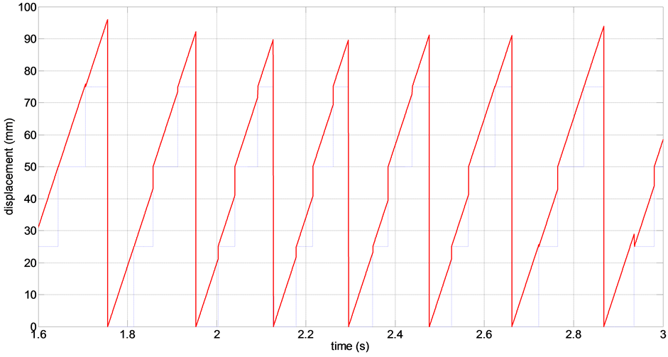
Figure 12. Estimation of position between data inputs.

Figure 13. Effect of position estimation in LSM stator discontinuity.
aspect is similar to Figure 14, however the vibratory shape is more noticeable due to the higher change of guideway surface.
5. Conclusion
In this study, the sensor application for position detection and guideway monitoring in high speed maglev was investigated and through the test bed experiment, the validity of examined method was confirmed. For position

Figure 14. Sensor outputs and calculated guideway irregularity (1mm step change).

Figure 15. Sensor outputs and calculated guideway irregularity (1.5 mm step change).
detection method, to detect the tooth-slot shape of LSM is proposed and this method has advantage over other methods in respect to accuracy and easiness of installation. To validate this method, by using the small scale testbed, the whole procedure of position data acquisition, processing and estimation are fulfilled and the effectiveness of estimation in the presence of missed data is proved. The experiment results show that the proposed method is suitable for position detection in maglev, and especially, the estimation method is very effective to improve the accuracy of position detection. For guideway surface irregularity monitoring during maglev running, the simple method using the displacement and acceleration data between vehicle and guideway surface is proposed. Through experiment by using small scale testbed, it was confirmed that the guideway surface irregularity such as step change could be effectively estimated. Even though, there is fluctuation at the beginning and some time is needed to be settled down, this method would be effective to anticipate the long wave irregularity of guideway.
Acknowledgements
This work was supported by Core Technology Development Project of Super Speed Maglev Train funded by Ministry of Land, Infrastructure and Transport (11PRTD-B061485).
References
- Lee, J.H., Jo, J.M., Han, Y.J. and Lee, C.Y. (2013) Thrust Performance Improvement through Position Signal Compensation and Estimation in Super Speed Maglev. Journal of the Korea Academia-Industrial Cooperation Society, 14, 4739-4746.
- Qian, C., Wei, R., Wang, X., Ge, Q. and Li, Y. (2011) Analysis the Position Signal Problem I Propulsion System with Long Stator Linear Synchronous Motor. The 21st International Conference on Magnetically Levitated Systems and Linear Drives, Daejeon, 10-13 October 2011.
- He, N., Xue, S., Long, Z.Q. and Zhang, J.N. (2012) Analysis and Optimal Design of Relative Position Detection Sensor for High Speed Maglev Train. The 15st International Conference on Intelligent Computation Technology and Automation, Zhangjiajie, 12-14 January 2012, 89-93.
- Wu, J., Zhou, W.W., Li, L. and Chang, W.S. (2011) Design of a Position Detection Sensor for Linear Synchronous Motors. The 21st International Conference on Magnetically Levitated Systems and Linear Drives, Daejeon, 10-13 October 2011.
- Liu, H.C., Zhang, S.T. and Wang, X.X. (2011) Position Sensing and Signal Transmission of Linear Synchronous Motor for High Speed Maglev. The 21st International Conference on Magnetically Levitated Systems and Linear Drives, Daejeon, 10-13 October 2011.
- Xue, S., Long, Z.Q., He, N. and Chang, W.S. (2012) A High Precision Position Sensor Design and Its Signal Processing Algorithm for a Maglev Train. Sensors, 12, 5225-5245. http://dx.doi.org/10.3390/s120505225
- Nieters, W. (2004) Guideway Monitoring during Operational Use on the First Transrapid Line in Shanghai. The 18th International Conference on Magnetically Levitated System and Linear Drives, Shanghai, 26-28 October 2004, 480- 485.
- Metzner, J. (2004) The TRANSRAPID Test Facility (TVE) Experience for Start up and Commissioning of Shanghai Maglev. The 18th International Conference on Magnetically Levitated Systems and Linear Drives, Shanghai, 26-28 October 2004, 139-145.
- Hauke, U. (2006) Guideway Maintenace. The 19st International Conference on Magnetically Levitated Systems and Linear Drives, Dresden, 13-15 September 2006.
- Shao, J.C. (2006) Alignment Measurement and Control of Maglev Track. The 19st International Conference on Magnetically Levitated Systems and Linear Drives, Dresden, 13-15 September 2006.
- Nieters, W. and Shao, J.C. (2008) Long Wave Guideway Contour Monitoring. The 20th International Conference on Magnetically Levitated System and Linear Drives, San Diego, 15-19 December 2008.
- Jo, J.M., Han, Y.J., Lee, J.H., Lee, C.Y. and Kim, Y.H. (2012) A Study on the Real-Time Measurement for Guideway Using Levitation System of High-Speed Maglev. Fall Conference of the Korean Society for Railway, Gyeongju, 18-20 October 2012, 1639-1643.