Modern Mechanical Engineering
Vol.4 No.3(2014), Article
ID:48800,6
pages
DOI:10.4236/mme.2014.43011
Numerical Simulation of Shock Resistant Microsystems (MEMS)
Yubin Lu1,2, Yongsheng Cheng1, Yuancheng Sun1
1Institute of Electronic Engineering, CAEP, Mianyang, China
2Ministry of Education Key Laboratory of Testing Technology for Manufacturing Process, Southwest University of Science and Technology, Mianyang, China
Email: yubinluzju@hotmail.com
Copyright © 2014 by authors and Scientific Research Publishing Inc.
This work is licensed under the Creative Commons Attribution International License (CC BY).
http://creativecommons.org/licenses/by/4.0/


Received 2 April 2014; revised 16 May 2014; accepted 15 June 2014
ABSTRACT
The mechanical response of shock-loaded microelectromechanical systems (MEMS) is simulated to formulate guidelines for the design of dynamically reliable MEMS. MEMS are modeled as microstructures supported on elastic substrates, and the shock loads are represented as pulses of acceleration applied by the package on the substrate over a finite time duration. For typical MEMS and shock loads, the response of the substrate is closely approximated by rigid-body motion. Results indicate that modeling the shock force as a quasi-static force for MEMS with low-natural frequencies may lead to erroneous results. A criterion is obtained to distinguish between the dynamic and quasi-static responses of the MEMS.
Keywords:Microelectromechanical Systems (MEMS), Shock, Reliability

1. Introduction
MEMS may expose dynamic loading during fabrication, deployment and operation, making shock-induced failures a significant reliability concern. For example, MEMS used in automotive applications are required to survive accidental drops onto hard surfaces. Similarly, MEMS used in space applications and those used to monitor intense impact environments are required to survive shock loading during deployment and operation, respectively [1] . There are a few experimental and theoretical studies of the reliability of particular devices. For example, Tanner et al. [2] performed tests on surface micromachined microengines using haversine shock pulses to determine the susceptibility; Wagner et al. [3] demonstrated an approach to improve shock resistance using dynamic finite element analysis for the case of polysilicon cantilevers; Younis et al. [4] presented computationally efficient models and approaches to simulate the response of microstructures under mechanical shock, Ref. [5] provided detailed analysis of the consequences of dropping a micro-machined transducer structure to a solid surface, and in Ref. [6] the reliability and the failure of the ultra-high measure range accelerometer under high impact environment were discussed. However, there are no guidelines for the design of reliable MEMS at present [7] . To facilitate formulating such guidelines, this study is focused on simulating the dynamic response of MEMS under mechanical shock.
2. Typical MEMS and Shock Loading
To analyze the dynamical reliability of MEMS, they are modeled as microstructures supported on elastic substrates. The microstructures, which are the operative mechanical elements of the device, range from a few microns to several millimeters in size [8] . The substrates are elastic plates (e.g., silicon, quartz) with thickness typically less than 1mm and lateral dimensions on the order of centimeters [8] . Since the substrates are invariably larger and more massive than the microstructures, it is reasonable to assume that the substrates influence the mechanical response of the microstructures, while themselves remaining immune to such responses.
The interaction of the substrate-microstructure assembly with the environment is mediated by the packaging of the MEMS. Such packages span a very large design space. In this analysis, it is assumed that 1) the package is only in mechanical contact with the substrate, and not the microstructures, and 2) the package isolates the substrate and the microstructure from direct mechanical contact with the environment (Figure 1), as stated in Ref. [9] .
The interaction of the package and the environment dictates the nature of the shock load transmitted to the substrates. Such interactions include accidental drops onto hard surfaces, shock tests in a laboratory, and exposure to ballistic environments. Regardless of their physical origins, however, shock loads can be represented as pulses of acceleration applied by the package on the substrate over a finite duration. Therefore, a shock load can be completely characterized by specifying the shape, the amplitude (usually reported as multiples of g, with g being the acceleration of gravity), and the duration of the applied acceleration. Such representation permits the analysis of the reliability of MEMS in a variety of shock environments using the same numerical model.
The shocks that occur during service are invariably irregular in pulse shape, jagged in spectral characteristics, and variable from one occurrence to another. Such shock environments can be conveniently approximated by a series of simple shock pulses in laboratory tests. A schematic illustration of a half-sine, saw-tooth, or rectangular shaped shock pulse, which is commonly used in shock testing of MEMS, is shown in Figure 2 [10] . The halfsine waveform is expressed as
 (1)
(1)
where τ is the duration of the load, and a0 is the amplitude of the shock. The amplitudes of shocks applied to MEMS can vary from 20 to 200,000 g, while the durations range from 40 to 3000 μs [7] . The goal is to analyze the response and reliability of MEMS subjected to such shock loads.
2. Numerical Analysis
In this work, a high-g shock resistant accelerometer with a silicon cantilever microbeam practically used was selected for finite element simulations under shock loading. It is defined that the accelerometer would measure the acceleration in direction Y. The schematic of the accelerometer was shown in Figure 3. The length, width and thickness of the microbeam are 1350 μm, 980 μm and 245 μm, respectively. Those of the mass are 1000 μm, 1000 μm and 300 μm, respectively. The commercial software ABAQUS/Explicit 6.10-1 was used in the finite element simulations. The microbeam is assumed to behave in an isotropic, linear elasticity way. The material parameters used in the model were listed in Table 1 [10] . The geometrical model is meshed with C3D8R elements. The meshed model was shown in Figure 4. The boundary condition of this model was that the left end of the microbeam was fixed. The shock loading of this model is applied on the bottom face of mass part with acceleration by defining the peak value and shock profile along the negative direction of Y. Half-sine, saw-tooth, or rectangular shaped shock pulses are employed. The duration of these
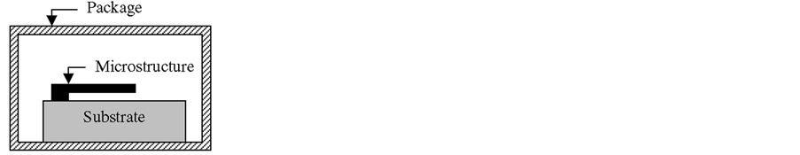
Figure 1. Schematic diagram of a packaged MEMS.
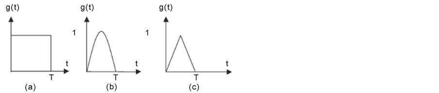
Figure 2. Simple shock pulses used to model actual shock loads, (a) rectangular, (b) half-sine, and (c) triangular pulses.

Figure 3. Schematic of the accelerometer.
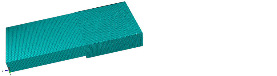
Figure 4. Mesh of the 3D finite element model.

pulses varies from 0.2 to 50 μs. Actual shock pulses from the projectile penetration tests are also used. Additionally, the microbeam is assumed to be placed in near vacuum conditions, which represents a worst case scenario since damping tends to suppress the response.
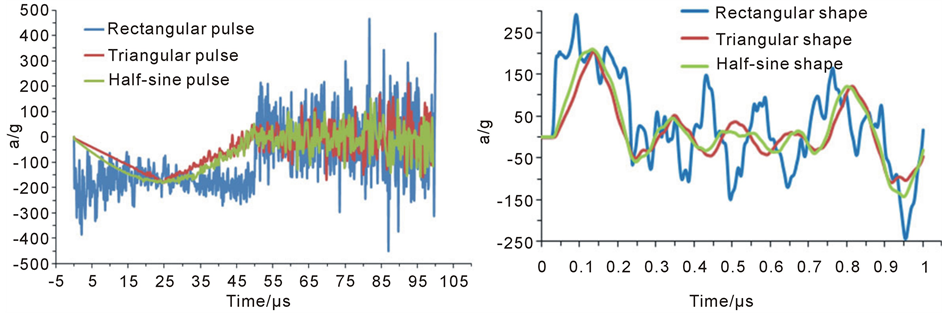
Figure 5(a) shows the time response of the microbeam to a mechanical shock pulse of amplitude 180 g and duration 50 μs. It is observed that when the shock profile is half-sine or triangular shape, the microbeam experiences the shock pulse as a quasi-static load (the response looks similar to the shock profile). This is because the first natural period of the microbeam is much smaller than the pulse duration. However, when the shock pulse has a rectangular shape, which contains a rich frequency contents, no matter how large is the duration of the pulse compared to the natural period of the structure, the structure responds dynamically, as can be seen from Figure 5(a).
Figure 5(b) shows the response of the same microbeam to similar shock pulses, but of duration 0.2 μs, which is close to the natural period of the microbeam. It can be seen that the microbeam experiences the shock loadings as dynamic loads. It is noted also that the maximum amplitude of the microbeam in Figure 5(b) is larger than that in Figure 5(a). This sensitivity of the response to the shock duration has to be taken into account when designing MEMS devices. Therefore, it is concluded from those two figures that a microstructure can experience a shock load as a quasi-static load or a dynamic load depending on the ratio between the natural periods of the structure and the time duration of the shock pulse. This result is in agreement with the conclusion of Srikar and Senturia [7] .
Figure 6 shows the time response of the microbeam to a triangular shock pulse of amplitude 68750 g and duration 0.2 μs. The shock amplification factor, which is the dynamic peak response normalized to the peak response due to a static load of the same amplitude as the shock load [4] , is approximately 1.14. Whereas for this shock pulse of amplitude 68750 g, the amplification factor is 1.17. This means that the dynamic response to a shock load is equivalent to a corresponding times that due to a static load of the same magnitude. This conclusion also applies to the case of a half-sine pulse shock.
 (a) (b)
Figure 5. The acceleration response of a cantilever microbeam subjected to a 180 g shock pulse with various profiles versus time. (a) τ = 50 μs; (b) τ = 0.2 μs.
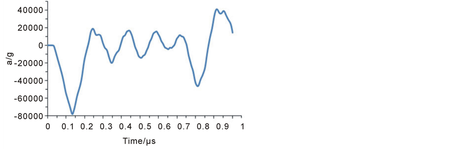
Figure 6. The acceleration response of a cantilever microbeam subjected to a 68750 g shock pulse with the triangular shape.
Actual shock pulses obtained from projectile penetration tests [11] as shown in Figure 7 are used to analyze the response of the microbeam. Figure 8 shows the acceleration response of the same microbeam aforementioned versus time. It is found that the microbeam behaves dynamically, and the amplification factor is much larger than that under the shock pulse of half-sine and triangular shapes.
3. Conclusion
The mechanical responses of a shock-loaded accelerometer are simulated by modeling it as a microstructure attached to an elastic substrate. For typical MEMS and shocks, the substrate responds as a rigid-body. It is found that the nature of the mechanical response of shock-loaded MEMS is governed by the relative magnitudes of three time scales, viz. the acoustic transit time, the time-period of vibrations and the duration of the applied load, and the shock pulse profile, which affects the frequency range. This criterion, obtained to distinguish between the dynamic and quasi-static responses of MEMS, agrees well with the existing study of Srikar and Senturia [7] .
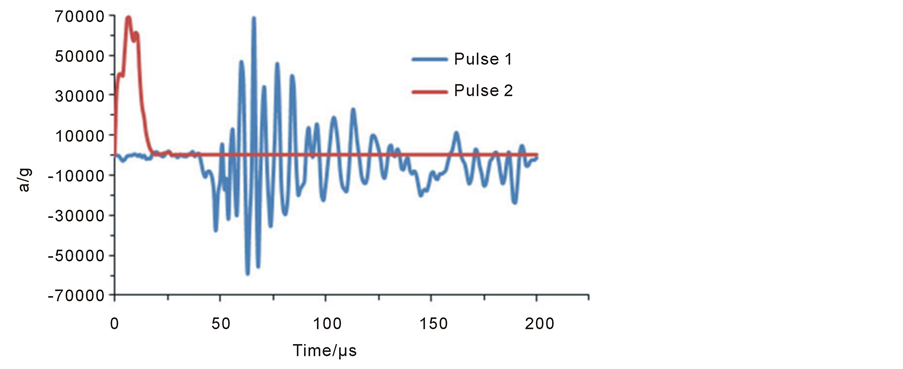
Figure 7. Examples of actual pulses for simulations.
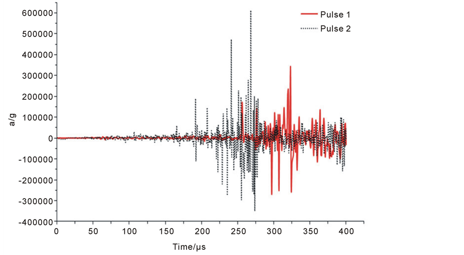
Figure 8. The acceleration response of a cantilever microbeam subjected to actual shock pulses.
Acknowledgements
The authors would like to acknowledge the support by the funding of China Postdoctoral Committee (2012 M511943).
References
- Srikar, V.T. and Senturia, S.D. (2002) The Reliability of Microelectromechanical Systems (MEMS) in Shock Environments. Journal of Microelectromechanical Systems, 11, 206-214. http://dx.doi.org/10.1109/JMEMS.2002.1007399
- Tanner, D.M., Walraven, J.A., Helgesen, K., Irwin, L.W., Brown, F., Smith, N.F. and Masters, N. (2000) MEMS Reliability in Shock Environments. IEEE International Reliability Physics Symposium, San Jose, 10-13 April 2000, 129138.
- Wagner, U., Franz, J., Schweiker, M., Bernhard, W. and Müller-Fiedler, R. (2001) Mechanical Reliability of MEMSStructures under Shock Load. Microelctronics Reliability, 41, 1657-1662. http://dx.doi.org/10.1016/S0026-2714(01)00173-1
- Younis, M.I., Jordy, D. and Pitarresi, J.M. (2007) Computationally Efficient Approaches to Characterize the Dynamic Response of Microstructures under Mechanical Shock. Journal of Microelectromechanical Systems, 16, 628-638. http://dx.doi.org/10.1109/JMEMS.2007.896701
- Li, G.X. and Shemansky Jr., F.A. (2000) Drop Test and Analysis on Micro-Machined Structures. Sensors and Actuators, 85, 280-286. http://dx.doi.org/10.1016/S0924-4247(00)00427-1
- Tang, J., Zhao, R., Shi, Y.B. and Liu, J. (2012) Failure Analysis of the MEMS Ultra High Measure Range Accelerometer Structure under High Impact Environment. Chinese Journal of Sensors and Actuators, 25, 483-486.
- Srikar, V.T. and Senturia, S.D. (2001) The Design and Analysis of Shock Resistant Microsystems (MEMS). The 11th International Conference on Solid-State Sensors and Actuators, Munich, 10-14 June 2001.
- Senturia, S.D. (2001) Microsystem Design. Kluwer, Norwell.
- Sun, Y.C., Yang, B., Peng, B., Zhao, L. and Zhang, Q.M. (2006) A Failure Mode of Micro Mechanical Shock Sensors. Chinese Journal of Sensors and Actuators, 19, 1610-1612.
- Jiang, Y.Q., Du, M.H., Huang, W.D., Xu, W. and Luo, L. (2003) Simulation on the Encapsulation Effect of the High-g Shock MEMS Accelerometer. Fifth International Conference on Electronic Packaging Technology Proceedings, Shanghai, 28-30 October 2003, 52-55.
- Lu, Y.B., Cheng, Y.S. and Sun, Y.C. (2013) Numerical Analysis on the Deceleration Characteristics of Flat-End Steel Projectiles Penetrating Steel Plates. Journal of Sichuan Ordnance, 35, 1-5.