Open Journal of Metal
Vol.07 No.01(2017), Article ID:74954,8 pages
10.4236/ojmetal.2017.71001
Metallurgical Analysis of Brake Blocks
Mathioro Fall1*, Fadel Niang2, Olivier Hubert3, Mamadou Babacar Ndiaye4
1UFR des Sciences de l’Ingénieur, Université de Thiès, Thiès, Sénégal
2Ecole Doctorale Développement Durable et Société-Université de Thiès, Thiès, Sénégal
3LMT-Cachan (ENS-Cachan/UMR/Université Paris Saclay), Cachan, France
4Institut Universitaire et Technologie, Université de Thiès, Thiès, Sénégal

Copyright © 2017 by authors and Scientific Research Publishing Inc.
This work is licensed under the Creative Commons Attribution International License (CC BY 4.0).
http://creativecommons.org/licenses/by/4.0/


Received: August 18, 2016; Accepted: March 26, 2017; Published: March 29, 2017
ABSTRACT
This study focuses on the characterization of train brake blocks. The brake blocks are an essential organ of train speed control system to ensure comfort and safety to passengers and crew. However, poor quality soles can cause a premature wear of the wheels whose consequences are on the one hand, a damaged brake function, and also high repair costs. Samples were carried out on 3 different batches of brake blocks. Their metallurgical characterization consisted of a study of the hardness and microstructural analysis (microstructures and chemical analyzes) of the different samples. The results show that the hardness of some soles is greater than that of the wheel, mainly associated with a cementite microstructure. This can lead to a premature wear of the wheels at the expense of brake blocks.
Keywords:
Brakes Blocks, Wheel, Microstructure, Hardness, Wear

1. Introduction
The braking system is among the most important elements in the rail transport sector. However, poor quality of this system may result, in economic terms, in very high maintenance and repair costs. It can also lead to much more serious security consequences [1] . Hence a good command of their manufacture should be a challenge.
We distinguish two braking modes in the rail transport: the first based on the adhesion and the second independent on adhesion. Our study is focused on the first mode in which the braking force is exerted on contact rails wheels. The braking torque is exerted by the friction of the brake blocks on the wheel: this mechanical braking differs from dynamic braking [2] .
From this point of view, the brake blocks must have appropriate mechanical properties including a good wear resistance and good adhesion. It must also avoid excessive wheel usury, leading to high repairing costs.
Thus, the brake block must be the “fuse” with respect to the wheel [3] .
Our work has focused on the study of the quality of brake blocks used in rail transport in Senegal. It should also be noted that in Senegal, the rail sector is experiencing real difficulties due to the use of obsolete equipment, and old production techniques.
This study is based primarily on the study of the hardness of samples soles, which will be complemented by microstructural characterization.
2. Braking Block System Description
The braking sole is a system in which the braking torque is exerted by the friction of brake sole on the wheel tread.
They are mounted on the soles-holders which rub against the wheel as shown in Figure 1.
The brake blocks are the first braking system used in the rail transport system. They were used on locomotives and on vehicles. It should also be noted that they are still used for wagons because of their low cost.
The brake block, constituting the contact element, must have a good resistance to wear in the face of the repetitive friction on the wheel. Thus, many materials have been tested for the manufacture of brake block. These are mainly cast iron, composite but also sintered materials.
The samples used in this study are cast iron. They are made from scrap metal. The manufacturing process at the foundry comprises five steps:
・ Modeling: all the different processes and means used to create a model;
・ Molding: manufacture of a mold (in sand) which bears the impression of the part, obtained from the model of the part to be manufactured;
・ Fusion: production of liquid metal from scrap metal;
・ Shake-off: recovery of the part after solidification and sufficient cooling;
・ Deburring: finishing operations.
3. Methodology
Experiments have been carried out on samples of brake blocks (bb), a raw cast iron alloy (rcia) and a train wheel (wh) as shown in Figure 2.
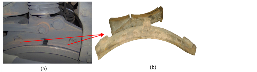
Figure 1. Braking system (a) and brake blocks (b).
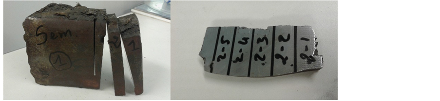
Figure 2. Samples of brake blocks.
The microstructures and chemical compositions were analyzed respectively by using an optical metallurgical microscope and an Energy Dispersive X-ray Spectrometer (EDS) attached with a scanning electron microscope (SEM).
The optical microscope OLYMPUS brand PMG3 connected to a computer with a Leica image analysis software is used for the observation of samples.
EDS Analysis with SEM, Hitachi brand, allowed the identification of the different alloying elements present in the samples as well as their mass and atomic proportions. Secondary electron (SE) images and analyses are complemented by backscattered electron (BSE) images, whose contrast is strongly sensitive to the atomic mass of elements submitted to the electron beam. The average chemical composition of the samples is obtained via large areas EDS measurements. Complementary local analyzes allowed the identification of the precipitates composition.
Vickers hardness measurements (HV) have been carried out too. The hardness measurement denoting the resistance of the material to the penetration of a diamond indenter, is a simple, fast and non-destructive test that evaluates the work hardening and surface heat treatment effect [4] . It may be employed to follow the diffusion kinetics [5] . The microhardness measurements were made with a Duramin microhardness of Struers brand. Macro hardness measurements were made with a Duramin 500.
4. Results and Discussion
Chemical composition results, microstructural observations and hardness measurements are presented below.
4.1. Chemical Composition
Table 1 summarizes the different chemical elements found in our samples and their various proportions in weight percent (wt %) obtained by EDS analysis.
The EDS analysis results in Table 1 show that the main components besides iron and carbon of the samples are: silicon Si (0.76 to 1.53 wt%), phosphorus P (0.46 to 1.16 wt%), sulfur, S (0.17 to 0.23 wt%) and manganese Mn (0.39 to 0.60 wt%).
Furthermore, the weight percentage of carbon is greater than 2 wt %. Hence, these results confirm that all samples belong to the family of non-alloyed cast iron; characterized by the following elements and their proportions [4] [6] :

Table 1. Chemical composition of the sample (weight percent).
・ Silicon Si: 0.76 to 1.53 wt%
・ Phosphorus P: 0.46 to 1.16 wt%
・ Sulfur S: 0.17 to 0.23 wt%
・ Manganese Mn: 0.39 to 0.60 wt%.
These elements have effects on the structures and properties of cast iron. Thus, the silicon increases the carbon activity and increases the carbon diffusion and prevents the connection between the iron and carbon, as to the phosphorus, it readily combines with the iron or the cementite forming a eutectic with a melting temperature is 950˚C with a cold-weakening effect. Note also the formation of cracks and blisters as shown in Figure 4(c) corresponding to the higher phosphorus content (Table 1) [7] [8] . Silicon and phosphorus favor the graphite formation. On the contrary, sulfur and manganese inhibit the graphite formation; they cannot bind iron but if the manganese content is sufficient there may be a sulphide forming Manganeses [7] [8] .
Otherwise the weight percentage of carbon of brake block 2 (4.17 wt%) is almost double that of the brake block 1 and 3 respectively equal to 2.64 and 2.48 wt %. However, cast iron may be classified according to carbon content by:
・ hypoeutectic cast iron : 2.1 to 4.3 wt%
・ Eutectic cast iron: 4.3 wt%
・ Hypereutectic cast iron: 4.3 to 6.67 wt%.
Thus brake block 2 carbon content is almost equal to eutectic cast iron. In addition, brake blocks 1, 2 and 3 are not manufactured by the same cast.
4.2. Microstructure
The microstructures of the samples are reported in Figure 3.
Analysis of the micrographs of Figure 3 shows that the brake blocks 1, 2 and the casting are made of gray cast iron having a grey appearance to fracture due to the presence of carbon mainly in the form of graphite [6] [9] [10] . As the brake block 3 is formed of a white cast iron have a white appearance to breakage. The carbon they contain is combined with the iron and form the carbide form called cementite.
4.3. Hardness
Two series of fifteen microhardness measurements (thirty indentations) were made on each sample. Average hardness of the core materials are regrouped in

Figure 3. (a), (b), (c) and (d) Microstructural respective brake blocks 1, 2, 3 and the cast iron alloy.
Microhardness profile of brake bloke 1, 2, 3 and of the cast iron alloy is shown in Figure 4.
Microhardness profile due to friction with the wheel and block brake 1 and 2 is represented in Figure 5.
Examination of Table 2 and Figure 4 shows that the hardness varied between 258 and 519 HV1 on all the samples tested. We note a slight difference between the brake block 1, the wheel and casting their respective whose hardness is 293, 295 and 302 HV1. The micrographs of Figure 3(a) and Figure 3(c) show that these samples belong to the family of gray cast iron. The latter in function of the shape of the graph are divided into several classes and can be characterized by more or less different hardness. [6] [9] [10] [11] . Fine shape and uniform distri- bution of the graphite in the casting (Figure 3(c)) explain the slight increase in hardness with respect to the brake block 1 and the wheel.
However, there is a great difference between the hardness of the brake block 3 and the other samples.
This is justified by its microstructure which consists of a white cast iron which is characterized by very low machinability, brittleness and high hardness. For this purpose, studies have shown that the hardness of the white irons varies be- tween 350 to 500 HB while that of the pearlite lamellar graphite cast irons is be- tween 170 to 270 HB, depending on the thickness of the pearlite lamellas, hence this difference observed hardness. [4] [6] [12] .
Microhardness profiles have been measured too. The basic idea of this mea- surement is to have an indicator of the effect of friction between the brake and the
Table 2. Average hardness.
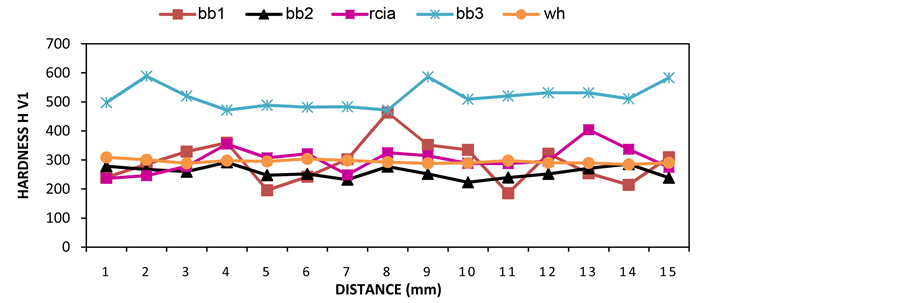
Figure 4. Hardness profile of brake blocks 1, 2, 3 and of the cast iron alloy.
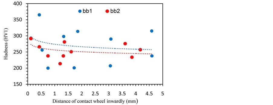
Figure 5. Microhadness profile due to friction with the wheel of brake blocks 1 and 2.
wheel. Figure 5 reports the microhardness profile of brake blocks 1 and 2.
The effect of strain hardening of brake block 1 and 2 is highlighted in Figure 5. This shows that the hardness is greater at the contact surface wheel/brake block up to about 1 mm inside the brake block and then starts to decrease linearly. This increase in hardness is due to the edge of the friction brake block onto the wheel. This hardening weakens and more cured the brake block which weakens its properties [13] .
Analysis of the samples shows defects that are even visible to the naked eye as shown in Figure 6 during the sample preparation. These defects called voids are described as closed or open cavities in walls rough dendritic dispersed or aligned with a sliding extension to heart thicknesses. These voids affect the quality of the molded part.
To avoid these voids, external reservoirs are created. They are called feeders and are used to improve the nutrition of parts which solidify last and also allow

Figure 6. Defaults in the cast iron alloy and respective brake blocks 1 and 3.
directing solidification towards the feeder using coolers [14] .
5. Conclusions
The study of sample hardness shows that samples can be classified into three categories depending on the hardness of the wheel:
・ Hardness lower than the wheel one: brake block 2;
・ Hardness substantially equal to that of the wheel one: brake block 1 and the casting;
・ Hardness greater than that of wheel one: brake block 3.
The microstructural observations show that the samples belong to the family of cast iron.
Thus, the brake shoes 1 and 2 and the casting is gray cast iron while the structure of the brake block 3 is a white cast iron.
However, these results show that the use of the brake block 3 will cause usury of the wheels and therefore we recommend a quality improvement in the production of brake block for a modernization of the smelter.
Thus, cast iron microstructure gray lamellar graphite with a pearlitic structure and hardness of between 170 HB and 230 HB are among the desirable properties for cast iron blocks.
Acknowledgements
The authors thank the brake blocks manufacturing company in Senegal for accepting to provide the samples analyzed. They also thank the University of Thies and the Cooperation and Cultural Action of the Embassy of France in Senegal for the allocated funding. Finally thanks go and Mechanics Laboratory of the Ecole Nationale Supérieure de Cachan Technology and the Faculty of Engineering of the University Pierre Marie Curie for allowing us to make the characterization tests.
Cite this paper
Fall, M., Niang, F., Hubert, O. and Ndiaye, M.B. (2017) Metallurgical Analysis of Brake Blocks. Open Journal of Metal, 7, 1-8. http://dx.doi.org/10.4236/ojmetal.2017.71001
References
- 1. Koenig, J.G. (2011) Rapport Bureau d’Enquêtes sur les Accidents de Transport Terrestre (BEA-TT).
- 2. Chapas, P. and Petit, J.M. (2004) Dimensionnement du matériel ferroviaire roulant. Technique de l’Ingénieur.
- 3. Annexe 2: Référence technique d’autorisation de mise en services des wagons. (2009)
https://www.bav.admin.ch/dam/bav/it/dokumente/internationale_vereinbarungen/eisenbahn/protocole_annexe2wagons.pdf.download.pdf/protocole_annexe2wagons.pdf. - 4. Dequatremare, M. and Devers, T. (2012) Précis de matériaux: de la conception aux controles. Dunod, Paris.
- 5. Spinelli, J.E., Silva, B.L., Cheung, N. and Garcia, A. (2014) The Use of a Directional Solidification Technique to Investigate the Interrelationship of Thermal Parameters, Microstructure and Microhardness of Bi-Ag Solder Alloys. Materials Characterization, 96, 115-125.
- 6. Les fontes, TBA 1064. (2004) Technique de l’Ingénieur.
- 7. Boulifa, M.I. and Hadji, A. (2015) Effect of Alloying Elements on the Structure and Mechanical Properties of Austempered Ductile Irons. Metallurgical Research & Technology, 112, 404.
- 8. Le Breton, H. (1966) Manuel pratique de fondeur de fonte. Dunod, Paris.
- 9. Rémy, A. (2014) Fontes à graphite lamellaire-Caractéristiques métallurgiques et mécaniques. Technique de l’Ingénieur.
- 10. Jault, J. (2001) Fontes à graphites sphéroïdal-Propriétés d’utilisation, Technique de l’Ingénieur.
- 11. Ashby, M.F. and Jones, D.R.H. (2014) Matériaux 2 Microstructures et procédés de mise en ouvre. 4e édition, Dunod, Paris.
- 12. Karsten, C.J.B. (1830) Manuel de la métallurgie du fer, volume 1. 2e édition, Madame Thiel.
- 13. Brunel, F. (2000) Etude thermomécanique du couple roue-semelle ferroviaire sous sollicitations de freinage, thèse de doctorat. Université de Lille I.
- 14. Dour, G. (2009) Aide-mémoire: Fonderie, alliages-procédés-propriétés d’usage-défauts. 2e édition, Dunod, Paris.