Open Journal of Composite Materials
Vol.04 No.04(2014), Article ID:50104,13 pages
10.4236/ojcm.2014.44020
Toughness Improvement of Geothermal Well Cement at up to 300˚C: Using Carbon Microfiber
Toshifumi Sugama, Tatiana Pyatina
Brookhaven National Laboratory, Sustainable Energy Technologies Department, Upton, USA
Email: sugama@bnl.gov, tpyatina@bnl.gov
Copyright © 2014 by authors and Scientific Research Publishing Inc.
This work is licensed under the Creative Commons Attribution International License (CC BY).
http://creativecommons.org/licenses/by/4.0/


Received 13 June 2014; revised 13 July 2014; accepted 30 July 2014
ABSTRACT
This study aimed at assessing the usefulness of carbon microfiber (CMF) in improving the compressive-toughness of sodium metasilicate-activated calcium aluminate/Class F fly ash foamed cement at hydrothermal temperatures of up to 300˚C. When the CMFs came in contact with a pore solution of cement, their surfaces underwent alkali-caused oxidation, leading to the formation of metal (Na, Ca, Al)-complexed carboxylate groups. The extent of this oxidation was enhanced by the temperature increase, corresponding to the incorporation of more oxidation derivatives at higher temperatures. Although micro-probe examinations did not show any defects in the fibers, the enhanced oxidation engendered shrinkage of the interlayer spacing between the C-basal planes in CMFs, and a decline in their thermal stability. On the other hand, the complexed carboxylate groups present on the surfaces of oxidized fibers played a pivotal role in improving the adherence of fibers to the cement matrix. Such fiber/cement interfacial bonds contributed significantly to the excellent bridging effect of fibers, resistance to the cracks development and propagation, and to improvement of the post-crack material ductility. Consequently, the compressive toughness of the 85˚-, 200˚-, and 300˚C-autoclaved foamed cements reinforced with 10 wt% CMF was 2.4-, 2.9-, and 3.1-fold higher than for cement without the reinforcement.
Keywords:
High Temperature, Alkali Activation, Carbon Fibers, Fly Ash, Calcium Aluminate Cement

1. Introduction
Sodium metasilicate (SMS)-activated calcium aluminate (CAC)/Class F fly ash (CFFA) cement, or Thermal Shock-Resistant Cement (TSRC), was developed earlier to withstand possible large temperature variations in Enhanced Geothermal Systems (EGSs) [1] . At the hydrothermal temperatures of 200˚ and 300˚C, this cement formed three major crystalline phases, 1) hydro-garnet including katoite [Ca3Al(OH)6] and hydrogrossular [Ca3Al2Si2(OH)4], 2) hydro-ceramic including hydroxysodalite [Na4Al3Si3O12(OH)], and Na-P-type zeolite [Na3Al3Si5O16.6H2O], and 3) hydro-Al oxide including gibbsite [Al(OH)3] and boehmite (γ-AlOOH). These phases were responsible for good thermal- and hydrothermal-stabilities at >300˚C, the retention of compressive strength of >6.89 MPa after five superheating-cooling cycles (one cycle: 500˚C heat for 24 hrs and 25˚C water-quenching), as well as an outstanding adherence (>60 psi) to the surface of steel casing. In addition to the named properties, the cementitious material must assure a long-term integrity of the well, zonal isolation and casing protection. Thus it must possess high resilience and toughness to survive under the harsh environments of geothermal wells.
A wide variety of discontinuous fibrous materials including steel [2] -[4] , glass [5] -[7] , nylon [8] -[10] , polypropylene [11] -[15] , and carbon [16] -[21] have been used as reinforcement to improve many resilience-related factors such as the resistance to crack development, arrest of crack propagation, strength, toughness, absorption of impact energy, durability in wear, ductility, and dimensional stability. A previous study [22] on the ceramic fiber-reinforced geothermal well cement composites demonstrated that the ideal fibers were required to meet the following material criteria: 1) good dispersion and mixing workability to achieve a uniform distribution in the cement slurry; 2) a thermal- and hydrothermal-resistance of ≥300˚C; 3) a minimum susceptibility to reactions with brine containing alkali- and alkaline earth-metals; and, 4) a moderate adherence to the cement matrix. Such organic fibers as nylon and polypropylene underwent a partial thermal degradation in the cement at temperatures of >200˚C [23] [24] . The major drawback of adding glass fibers was its high susceptibility to alkali earth metals, in particular, calcium, leading to the precipitation of calcium hydroxide (CH) on the fiber’s surfaces in the cement matrix [25] . The growth of CH crystals over fibers in hydrothermal environments at high temperature is detrimental to the fibers performance. A passive iron oxide forms on the surface of steel fibers when in contact with the cement’s alkaline pore solution of pH > 12. Such passive layer protects the steel against corrosion but is susceptible to attack of chloride ions in brine environments [26] -[28] . In addition, the other disadvantage of using the strong and stiff steel fibers is their tendency to tangle and ball up, so lowering the workability of cement slurry, and, accordingly, limiting the amount of fiber that can be incorporated into the cement.
Compared with the shortcomings of these fibrous materials as reinforcing additives of the geothermal well cements, carbon fibers seem to meet all the material requirements. In fact, studies of the interfacial bonds between carbon fiber and Ordinary Portland Cement at a hydrothermal temperature of 300˚C [29] [30] demonstrated presence of such functional groups as carbonyl, carboxyl and carboxylic acid in the fibers’ surface layer of ~5 nm. These groups not only assured good water-wetting behavior and uniform dispersion of fibers in the cement slurry, but also interacted with ionic cement species forming an interfacial bond between the fibers and cement.
The carbon fibers undergo alkali oxidation by a NaOH solution at 80˚C leading to the increased number of these functional groups on fibers’ surface. Such an alkali sensitivity raises the concern about the physical and thermal stability of the fiber in the SMS-activated CAC/CFFA cement with a pH > 13 at temperatures up to 300˚C.
Earlier study on the α-Al2O3/mullite ceramic fiber [22] revealed a very strong interfacial bonding between the fibers and the cement matrix. This extensive interaction with the cement converted the strong, flexible and tough fibers into fragile, brittle ones. Correspondingly, the cracks generated in the fiber/cement composite were propagated through the fibers’ ruptures instead of disbanding at fiber/matrix interfaces. This fact strongly demonstrates that moderate interfacial bonding is required to improve the process of transferring frictional stress from the cement matrix to the crack-bridging fiber. Additionally, shorter fibers along with a lower general aspect ratio are easier to incorporate in larger amounts into cement slurry without compromising workability of the slurry.
The objective of this study was to assess the usefulness of carbon microfiber for reinforcing and improving toughness of the air-foamed TSRCs after autoclaving at 85˚C, 200˚C, and 300˚C. Three other carbon-based additives currently used for lost circulation control, mechanical lubrication and flow improvement in drilling fluids were also evaluated. They included graphite flakes, carbon beads, and calcinated petroleum coke. The present study focused on fibers’ susceptibility to the cement pore solution assessing the changes in chemical composition, thermal stability and crystallinity of pore solution-treated fibers. It also evaluated the chemical affinity of the oxidized surface of the fibers with the cement and explored the microstructure developed at the fiber-cement interface. Finally, the changes in compressive strength and compressive toughness of TSRC as a function of hydrothermal temperature and fibers’ content were measured.
2. Experimental Procedures
2.1. Materials
Carbon microfibers (CMF, AGM-94) derived from a polyacrylonitrile (PAN) precursor was supplied by Asbury Graphite Mills, Inc. The fibers were 7 - 9 µm in diameter and 100 - 200 µm in length, their visual appearance was a powder-like product. Asbury Graphite Mills also provided the three other micro-size carbon-based materials, graphite flakes (GF, 3226) of the size between 75 and 355 µm, carbon micro-beads (CMB, Carbobeads) of the size between 53 and 425 µm, and calcinated petroleum coke (CPC) of the size between 75 and 425 µm. Class F fly ash (CFFA) was obtained from Boral Material Technologies, Inc., and its chemical composition detected by micro energy-dispersive X-ray spectrometer (mEDX) was as follows: 50.4% SiO2, 34.8% Al2O3, 7.1% Fe2O3, 3.1% K2O, 2.7% CaO, 1.6% TiO2, and 0.4% SO3. A sodium metasilicate (SMS) granular powder under the trade name “Metso Beads 2048,” supplied by the PQ Corporation was used as the alkali activator of CFFA. Its chemical composition was 50.5 wt% Na2O and 46.6 wt% SiO2. Calcium aluminate cement (CAC, Secar #80) was supplied by Kerneos Inc. The X-ray powder diffraction (XRD) data showed that the crystalline compounds of CFFA had three major phases, quartz (SiO2), mullite (3Al2O3∙2SiO2), and hematite (Fe2O3), while CAC encompassed three crystalline phases, corundum (α-Al2O3), calcium monoaluminate (CaO∙Al2O3, CA), and calcium dialuminate (CaO∙2Al2O3, CA2). Halliburton supplied the cocamidopropyl dimethylamine oxide-based foaming agent (FA) under the trade name “Zone Sealant 2000”.
A cementitious dry-blend consisted of 60 wt% CAC and 40 wt% CFFA. The SMS was added at 6.2% by total weight of the blend. Further, the carbon-based reinforcing additives, CMF, GF, CMB, or CPC, were added at 10% by weight of CAC/CFFA/SMS blend to prepare one dry cement mixture. In preparing the foamed reinforced cements, 0.2% FA by weight of water was added. The following sequence was employed in making the foamed cement slurry. First, FA was blended in water; second, this water with FA was incorporated into a dry cement blend; the water/cement ratios for all carbon additive-reinforced and non-reinforced cements were 0.56 and 0.5, respectively; and, finally, these foamed cement slurries were mixed thoroughly at 20,000 rotations per minute in a Warring blender for 30 sec. The blending generated aerated smooth creamy slurry with a vast number of air bubbles. The density of the foamed cement slurries ranged from 1.25 to 1.38 g/cm3. To determine the compressive-strength and -toughness, the slurries were cast in cylindrical molds (20 mm diam. and 40 mm high), and left to harden for 2 days at room temperature. Thereafter, the hardened foamed cements were removed from the molds and autoclaved at 85˚C, 200˚C or 300˚C for 24 hours under a pressure of 6.9 (1000) MPa (psi).
2.2. Measurements
The compressive-strength and toughness were determined using Electromechanical Instron System. To investigate whether the surface of CMF reacts with the cement, the CMF was immersed in a pore solution extracted centrifugally from a cement slurry 10 minutes after the slurry mixing and autoclaved at 85˚C, 200˚C or 300˚C for 24 hours. The pH of this pore solution was 13.3. The treated CMF then was washed with DI water and dried at 90˚C for the analyses by Attenuated Total Reflectance-Fourier Transform Infrared Spectroscopy (ATR-FTIR), X-ray Diffraction (XRD), and Micro Energy-Dispersive X-ray (μEDX). Thermogravimetric Analysis (TGA) at the heating rate of 20˚C/min in a N2 flow was used to determine the thermal stability of pore solution-treated CMF. Further, to assess how well CMF adheres to the cement matrix and to explore the development of microstructure at the cement/fiber interfaces, the fractured surfaces of 85˚C-, 200˚C- and 300˚C-autoclaved CMF- reinforced cements were analyzed by High-Resolution Scanning Electron Microscopy (HR-SEM) concomitant with Energy-Dispersive X-ray (EDX).
3. Results and Discussion
3.1. Cement Pore Solution-Treated CMF
Figure 1 illustrates ATR-FTIR spectra in the wavenumber region, 1650 - 1300 cm−1, of the non-treated CMFs and CMFs immersed in pore solution at 200˚C or 300˚C. Compared with the monotone spectrum of the non-immersed CMF, the 200˚C-immersed CMF showed the appearance of two absorption bands at 1571 and 1424 cm−1. Increasing the treatment temperature to 300˚C caused a marked growth of 1571 cm−1 band. The band at 1424 cm−1 may belong to
 in the carbonate compounds formed by the carbonation of Na+ and Ca2+ ions present in the pore solution or, alternatively, these two bands can be ascribed to the carboxylate anions, -COO− [31] [32] in the metal-complexed carboxylate groups; namely, the C-O asymmetric and symmetric stretching modes in this group at 1571 and 1424 cm−1, respectively. Conceivably, the metallic cations are Ca2+, Na+, and Al3+ liberated during cement hydration. If this explanation is correct, the CMF was oxidized by the pore solution, and the extent of the oxidation increased as the temperature rose. Metal-complexed carboxylate groups were incorporated into the CMF surface at 300˚C.
Figure 2 depicts the XRD traces for pore solution-treated and non-treated CMFs. For the latter, the typical XRD pattern (a) of graphitized PAN fibers includes two d-spacings at 0.352 and 0.208 nm attributed to the carbon basal planes made of the aromatic structures [20] [33] [34] . When this CMF was treated with a pore solution at 85˚C, its pattern (b) included the crystalline sodium metasilicate, Na2SiO3, from the SMS used as alkaline activator, while two carbon basal planes-related d-spacings were shifted to lower spacing side. Further shift of these spacings was observed from the CMF treated at 200˚ (c) and 300˚C (d), suggesting that the interlayer spacing between the C-basal planes gradually shrank as the treatment temperature increased. Also, the pattern revealed the formation of crystalline gonnardite, CaNa2Si6Al4O20∙7H2O, phase derived from hydrothermal reactions of sodium metasilicate with Ca and Al in the pore solution. In fact, no sodium metasilicate was detected on 200˚C- and 300˚C-treated CMFs.
In support of the XRD results, Figure 3 compares the µEDX results on the amount of the oxides of three major cement-related elements, Ca, Si, and Al, deposited on CMFs at 85˚C, 200˚C, and 300˚C. At 85˚C, SiO2 was the major precipitate and CaO―the minor one. Relating this evidence to XRD data, SiO2 appeared to be associated with the crystalline sodium metasilicate. Increasing the temperature to 200˚C promoted the precipitation of calcium, from 1.6% at 85˚C to 6.4%, and caused precipitation of some aluminum on CMFs. Further raising temperature to 300˚C enhanced the precipitation of both Ca and Al by 1.6- and 1.8-fold, respectively, compared with that at 200˚C. These oxides were related to the gonnardite phase. Also, based on ART-FTIR results it is reasonable to suggest that the metals could be associated with carboxylate groups over the oxidized CMF’s surface at an elevated temperature. Additionally, the µEDX images did not reveal any remarkable damage or breakage of CMFs caused by the hot alkali attack during autoclaving at 300˚C.
Figure 4 shows the TGA curves of the non-treated, 85˚C and 300˚C pore-solution-treated CMFs. The curve for the non-treated CMF revealed some gain in weight between 25˚ and 150˚C, accounted for by the uptake of N2 gas by CMF. Beyond this temperature, it leveled off until the major decomposition stepat Td1 of 560˚C. The 85˚C pore solution-treated CMF curve exhibited two distinct decomposition steps: the fiber’s weight gradually fell with an increasing temperature between 25˚C and ~300˚C, and then its major decomposition, Td1, began at ~537˚C, which is 25˚C lower than that of the control. A small weight loss of less than 2% in the first step was due to the elimination of moisture absorbed by CMF. In contrast, the thermal decomposition curve of 300˚C

Figure 1. ATR-FTIR spectra, in the range from 1650 to 1300 cm−1, for non-treated CMF (a), and pore solution- treated CMFs at 200˚C (b), and 300˚C (c).

Figure 2. XRD patterns of non-treated CMF (a), CMFs exposed to 85˚C (b), 200˚C (c), and 300˚C (d) pore solution.

Figure 3. Compositions of cement-related oxides precipitated on CMFs after immersion in the pore solution at 85˚C, 200˚C, or 300˚C.
pore-solution-treated CMF was characterized by three steps: in the first step, the ~1.4% moisture loss took place between 25˚C and ~200˚C; in the second step ~4.2% weight loss occurred between 268˚C (Td1) and ~450˚C; and, the final weight loss happened between 500˚C (Td2) and 650˚C. The second step in the decomposition

Figure 4. TGA curves for non-treated CMF (a), 85˚C (b) and 300˚C (c) pore- solution-treated CMFs.
processes presumably involved the dehydration of gonnardite phase deposited on CMFs, while the third step, which began at 500˚C, was due to the decomposition of CMF itself. Hence, the onset of CMF’s decomposition temperature shifted from 560˚C of the control to lower temperatures of 537˚C and 500˚C, respectively, after treating the fibers at 85˚C and 300˚C in the cement pore solution. These results suggest that CMF’s thermal stability declined after fibers exposure to an alkali environment at pH ~13 at high temperatures and 6.9 (1000) MPa (psi) pressure. The decline is likely associated with the alkali oxidation of CMF and the shrinkage of interlayer spacing between the C-basal planes.
3.2. Compressive-Strength and -Toughness
Figure 5 shows the compressive strength of 10 wt% CMF-, GF-, CMB-, or CPC-reinforced and non-reinforced foamed cements after autoclaving at 85˚C, 200˚C, or 300˚C for 24 hours. The non-reinforced foamed cement developed a compressive strength of 3.03 (440), 5.00 (726), and 7.78 (1129) MPa (psi) at 85˚C, 200˚C, and 300˚C, respectively. When this cement was fortified with CMF, its compressive strength rose 1.5-, 1.3-, and 1.3-fold to 4.48 (650), 6.42 (932), and 10.23 (1485) MPa (psi) at 85˚C, 200˚C, and 300˚C, demonstrating that the CMF offered a better compressive strength of SMS-activated CAC/CFFA foamed cements in this temperature range. In contrast, no pronounced improvement of strength was observed from any other carbon-based reinforcement. Furthermore, adding the CMB or CPC caused a decline in strength compared to that of the control. The efficiency of strength improvement by reinforcing materials was computed according to the following formula: Efficiency (%) = [(CSRC ? CSNRC)/CSNRC] × 100; where, CSRC = compressive strength of reinforced cement and CSNRC = compressive strength of non-reinforced cement (Figure 5). The efficiency of CMF was 48%, 28%, and 31% at 85˚C, 200˚C, and 300˚C, suggesting that the CMF was more effective in improving the strength for 85˚C-autoclaved cement, than that of 200˚C- and 300˚C-autocaved ones.
Figure 6 shows stress-strain curves for the control and CMF-reinforced cements autoclaved at 85˚C. Two regions marked under the curve of the control sample are: a) the pre-stress energy absorption or ultimate strength and b) post-stress energy absorption or ductility. The former region represents the energy absorbed by cement up to the peak stress where it yields and the latter is the energy absorbed between the peak stress and the failure. The toughness is a combination of the strength and ductility per unit volume measured in J/mm3. It was determined as the total energy absorbed before the cement compressive failure and calculated from the enclosed area of the stress-strain curve with the baseline extending between the onset and the end of the peak.
For the CMF reinforced cement the applied stress gradually increased reaching the peak at much higher strain value instead of sharply increasing at a small strain for the control cement. The maximum stress was also higher for the reinforced cement and the post-stress energy absorption was large reflecting a great ductility. The

Figure 5. Comparison of reinforced cement compressive strength and efficiency of the different carbon-based materials in increasing it.
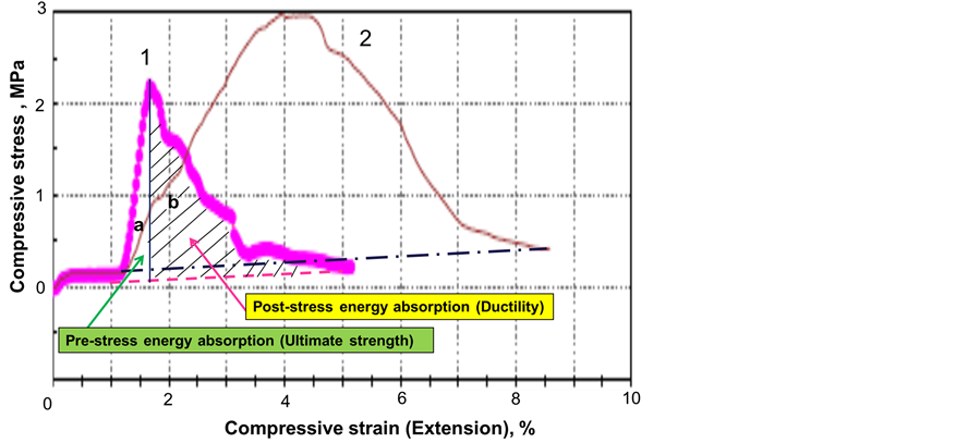
Figure 6. Comparison of the stress-strain curves for non-reinforced (1) and CMF-reinforced (2) foamed cements after autoclaving at 85˚C.
appearance of a convex-shaped curve between zero stress and the peak stress is due to the bridging effect of CMF controlling the generation and propagation of cracks in the cement. The convex curve after the maximum stress represents the slow propagation of the cracks due to the persistence of the fiber/matrix interfacial bonds, which break at many different angles extending the local deformations. Thus, CMFs obviously improved both ultimate strength and ductility, strongly demonstrating great potential as toughness-enhancing material for foamed cement.
Figure 7 compares the compressive toughness of cements modified with different carbon-based materials and effectiveness of these materials in cement reinforcement. The results are similar to those of the compressive strength; namely, all the carbon-based additives except the CMF had no effect on cement toughness. CMF’s efficiency in increasing the toughness was as high as 143%, 188%, and 207% at 85˚C, 200˚C, and 300˚C. Figure 8 depicts the changes in efficiency of compressive-strength and toughness increase as a function of the CMF content. The data clearly revealed that the impact of CMF on the improvement of toughness was far greater than its impact on the compressive strength. Furthermore, the magnitude of CMF’s efficiency for enhancing toughness depended on the hydrothermal temperature; namely, it was larger at higher temperature. Correspondingly,
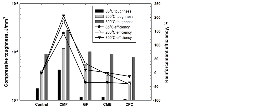
Figure 7. Comparison of cement compressive toughness and efficiency of different carbon-based materials in increasing it.

Figure 8. Comparison of CMF efficiency in improving compressive strength and toughness of 85˚C-, 200˚C-, and 300˚C-autoclaved foamed cements.
at 300˚C, incorporating only 3 wt% CMF ensured an excellent efficiency of more than 150%.
3.3. Microstructure Development at Cement/CMF Interface
Observation of microstructures developed in cement re-enforced with the fibers at different temperatures could help to better understand the outstanding performance of CMF in enhancing the toughness. Figure 9 shows a microphotograph of the original CMFs. The length of fibers ranged from 100 to 200 mm. The close examination (Figure 9(b)) of fibers’ surfaces revealed the presence of many gutters oriented along the fibers’ axes.
A set of SEM pictures shows morphological aspects of the studied system after curing at 85˚C, 200˚C and 300˚C for 24 hours (Figures 10-13). Table 1 gives information on chemical composition of the cement hydration products in the main cement matrix, on the fibers and in the fibers’ prints left after the displacement of fibers. The average “Si/Ca”, “Si/Al” and “Ca/Al” ratios are given in bold italic. Although these values should be considered with caution since the cementitious material is not uniform, they allow an easier comparison of results

Figure 9. SEM image at low―(a) and high (b)―magnification of the “as-re- ceived” CMF.

Figure 10. SEM micrographs of TSRC re-enforced with CMF fibers autoclaved at 85˚C.
at three test temperatures.
At 85˚C together with unreacted species there exists the amorphous aluminosilicate gel (Figure 10, points 8, 9, 10, 11, 13). From the EDX analysis (see Table 1), average composition ratios of Si/Al = 0.35, Si/Ca = 1.31 and Ca/Al = 0.3 were deduced for the main cement matrix. The prints left from the fibers had slightly lower Si/Al and much lower Si/Ca ratios but higher Ca/Al ratio (Si/Al = 0.3, Si/Ca = 0.28 and Ca/Al = 0.47). Higher Ca/Al and lower Si/Ca ratios suggest higher than in matrix concentration of calcium in the prints, which could be due to calcium interactions with the fibers. However, these interactions are weak since Ca presence on the fibers is not as important as in the prints (higher Si/Ca, 0.61, and lower Ca/Al, 0.28, ratios). Finally, in comparison with the cement matrix the cement elements on the fibers are present at much lower Si/Ca, lower Si/Al and similar Ca/Al ratios (Si/Ca = 0.61, Si/Al = 0.22 and Ca/Al = 0.28). This suggests a preferential adherence of Ca and Al in comparison with Si to the fibers. Low cement coverage of the fibers along with the long fiber prints and fibers pulled out of the cement indicate a weak bonding between the cement and the fibers at that temperature.
The atomic ratios of cement elements associated with the fibers change significantly at 300˚C. The Si/Ca ratio
 1Boundary between the matrix and the grout.
Table 1. EDX microanalysis on specific points of the samples (atomic data).

Figure 11. SEM micrographs of TSRC re-enforced with CMF fibers autoclaved at 200˚C.

Figure 12. SEM micrographs of TSRC re-enforced with CMF fibers autoclaved at 300˚C.

Figure 13. Microstructure developed after the failing of 300˚C-autoclaved fiber-reinforced cement.
rises while Ca/Al decreases (1.87 and 0.17 at 300˚C vs. 0.22 and 0.28 at 85˚C) suggesting increase in Si and Al concentrations. This is likely due to the further dissolution of fly ash, which is a source of Al and Si ions, and precipitation of its hydration products at the high temperature. The fiber surface gets increased amount of Al (Ca/Al and Si/Al are 0.17 and 0.28 on the fiber vs. 0.3 and 0.66 in the main matrix). Aluminum forms relatively strong bonds with the fibers modified by the high temperature and alkali environment, probably through formation of carboxylates. When the fibers dislodge from the matrix Al stays on fibers’ surface and the prints have depleted Al content (Si/Al―0.81 vs. 0.28 on the fiber and 0.66 in the matrix). Silicon on the other hand does not have any important interactions with the fibers, which is evident from the lower Si/Al and Si/Ca ratios on the fibers than in the matrix (0.28 and 1.87 vs. 0.66 and 2.55 respectively).
The SEM image of the fractured 300˚C-autoclaved composite shows good fiber’s dispersion (Figure 13). As described in the introduction section, the surface of fibers originally had hydrophilic functional groups such as carbonyl, carboxyl, and carboxylic acid, which ensured fibers good water-wetting and easy mixing with cement slurries. Fibers incorporated into the cement matrix in a large amount, were uniformly distributed throughout. Also, this image highlighted the bridging effect of fibers that helped to prevent cracks’ development, growth, and propagation and to improve the post-crack ductile performance.
The 200˚C sample shows an intermediate chemical composition and bonding in comparison with the 300˚C- and 85˚C-cured fiber-re-enforced cements (Figure 11). Si/Al and Si/Ca ratios in the matrix are the lowest at that temperature. Surprisingly the Ca/Al ratio is significantly lower on the fiber than in the prints/matrix. That could be the result of too few measurements or/and more important aluminum dissolution than calcium in this sample, e.g. due to the CA2 hydration, which takes place at later times/higher temperature than dissolution of CA. Aluminum is likely to react with the carboxylic groups on the fiber leading to higher fiber-associated Al content (Ca/Al is 0.47 on the fiber surface vs. 1.52 in the matrix and 1.61 in the print). The cement deposition on the fiber increased at 200˚C in comparison with 85˚C. There were two failure modes when the sample was broken― one a cohesive mode in cement matrix and the other, an adhesive one, at the cement-fiber interface. Based upon this mixed failure mode, the adherence of CMFs to cement matrix after autoclaving at 200˚C can be described as a moderate bonding; furthermore, some cracks had propagated through the matrix without significantly displacing the fibers. The fiber-cement bonding played an important role in transferring the frictional stress from the matrix to the fibers improving the toughness of the cement.
4. Conclusions
This study aimed at evaluating the usefulness of polyacrylonitrile (PAN) precursor-derived carbon microfibers (CMF), 7 - 9 µm in diameter and 100 - 200 µm long, in improving the toughness of the sodium metasilicate (SMS)-activated calcium aluminate/Class F fly ash foamed cement (slurry density: 1.25 - 1.38 g/cm3) under hydrothermal temperatures, ranging from 85˚C to 300˚C, at the pressures of 6.9 (1000) MPa (psi). The main conclusions are as follows.
The surface of CMF undergoes an alkali oxidation in cement’s pore solution, pH 13.3, with the formation of carboxylates of Na, Ca, and Al. The cations come from the dissolution of the cementitious blend. More carboxylates forms at higher temperatures due to the larger extent of CMF oxidation. Although the microprobe examinations did not show any marked degradation of the fibers such as fibers’ ruptures, the enhanced oxidation caused the shrinkages of interlayer spacing between the C-basal planes in the fibers and the decline of their thermal stability.
Nevertheless, the performance of fibers in fortifying the foamed cement was outstanding compared with that of other carbon-based reinforcing materials. The improvement in materials’ toughness was far greater than in the compressive-strength. Further, the magnitude of the fibers’ efficiency in increasing the toughness depended on the hydrothermal temperature; namely, it rose as the temperature increased. In fact, at 300˚C, the efficiency of >150% was attained by adding only 3 wt% fiber to the foamed cement. The two major factors that contributed to the performance of the fibers were fibers uniform distribution throughout the cement matrix due to their good water wetting behavior and fibers interactions with the cement matrix. For the latter, metal-complexed carboxylate groups present on the fibers’ surfaces seem to play a role in cement-fibers adherence. The moderate bond at the cement-fibers interface allowed the prevention of micro-cracks growth, the resistance to the development of cracks, the arrest of the cracks’ propagation, and the improvement of the post-crack ductile performance. Although an extended curing test is still required to ensure the long-term performance of CFMs, the fibers have already demonstrated good potential as a toughness-improving additive for high-temperature well cements.
Acknowledgements
This publication is based on the research issued by Geothermal Technologies Office in DOE Energy Efficiency and Renewable Energy (EERE), was performed under the auspices of the US Department of Energy, Washington, DC, under Contract No. DE-AC02-98CH10886. The research was carried out in part at the Center for Functional Nanomaterials, Brookhaven National Laboratory, which is supported by the U.S. Department of Energy, Office of Basic Energy Sciences, under Contract No. DE-AC02-98CH10886.
References
- Gill, S., Pyatina, T. and Sugama, T. (2012) Thermal Shock-Resistant Cement. Geothermal Resources Council (GRC) Transactions, 36, 445-451.
- Lau, A. and Anson, M. (2006) Effect of High Temperatures on High Performance Steel Fiber Reinforced Concrete. Cement and Concrete Research, 36, 1698-1707. http://dx.doi.org/10.1016/j.cemconres.2006.03.024
- Banthia, N. and Sappakittipakorn, M. (2007) Toughness Enhancement in Steel Fiber Reinforced Concrete through Fiber Hybridization. Cement and Concrete Research, 37, 1366-1372. http://dx.doi.org/10.1016/j.cemconres.2007.05.005
- Abrishambaf, A., Barros, J.A.O. and Cunha, V.M.C.F. (2013) Relation between Fiber Distribution and Post-Cracking Behavior in Steel Fiber Reinforced Self-Compacting Concrete Panels. Cement and Concrete Research, 51, 57-66. http://dx.doi.org/10.1016/j.cemconres.2013.04.009
- Marikunte, S., Aldea, C. and Shah, S.P. (1997) Durability of Glass Fiber Reinforced Cement Composites: Effect of Silica Fume and Metakaolin. Advanced Cement Based Materials, 5, 100-108. http://dx.doi.org/10.1016/S1065-7355(97)00003-5
- Purnell, P., Short, N.R., Page, C.L., Majumdar, A.J. and Walton, P.L. (1999) Accelerated Aging Characteristics of Glass-Fiber Reinforced Cement made with New Cementitious Materials. Composites Part A: Applied Science and Manufacturing, 30, 1073-1080. http://dx.doi.org/10.1016/S1359-835X(99)00019-6
- Enfedaque, A., Cendon, D., Galvez, F. and Sanchez-Galvez, V. (2010) Analysis of Glass Fiber Reinforced Cement (GRC) Fracture Surfaces. Construction and Building Materials, 24, 1302-1308. http://dx.doi.org/10.1016/j.conbuildmat.2009.12.005
- Ozger, O.B., Girardi, F., Giannuzzi, G.M., Salomoni, V.A., Majorana, C.E., Fambri, L., Baldassino, N. and Di Maggio, R. (2013) Effect of Nylon Fibers on Mechanical and Thermal Properties of Hardened Concrete for Energy Storage Systems. Materials and Design, 51, 989-997. http://dx.doi.org/10.1016/j.matdes.2013.04.085
- Yap, S.P., Alengaram, U.J. and Jumaat, M.Z. (2013) Enhancement of Mechanical Properties in Polypropylene- and Nylon-Fiber Reinforced Oil Palm Shell Concrete. Materials and Design, 49, 1034-1041. http://dx.doi.org/10.1016/j.matdes.2013.02.070
- Song, P.S., Hwang, S. and Sheu, B.C. (2005) Strength Properties of Nylon- and Polypropylene-Fiber-Reinforced Concretes. Cement and Concrete Research, 35, 1546-1550. http://dx.doi.org/10.1016/j.cemconres.2004.06.033
- Toutanji, H.A. (1999) Properties of Polypropylene Fiber Reinforced Silica Fume Expansive-Cement Concrete. Construction and Building Materials, 13, 171-177. http://dx.doi.org/10.1016/S0950-0618(99)00027-6
- Stroeven, P. (2000) Development of Hybrid Polypropylene-Steel Fiber-Reinforced Concrete. Cement and Concrete Research, 30, 63-69. http://dx.doi.org/10.1016/S0008-8846(99)00202-1
- Kurtz, S. and Balaguru, P. (2000) Postcrack Creep of Polymeric Fiber-Reinforced Concrete in Flexure. Cement and Concrete Research, 30, 183-190. http://dx.doi.org/10.1016/S0008-8846(99)00228-8
- Tang, C.S., Shi, B., Gao, W., Chen, F.J. and Cai, Y. (2007) Strength and Mechanical Behavior of Short Polypropylene Fiber Reinforced and Cement Stabilized Clayey Soil. Geotextiles and Geomembranes, 25, 194-202. http://dx.doi.org/10.1016/j.geotexmem.2006.11.002
- Sukontasukkul, P. and Jamaswang, P. (2013) Use of Steel and Polypropylene Fibers to Improve Performance of Deep Soil-Cement Column. Construction and Building Materials, 29, 201-205. http://dx.doi.org/10.1016/j.conbuildmat.2011.10.040
- Larson, B.K., Drzal, L.T. and Sorousian, P. (1990) Carbon Fiber-Cement Adhesion in Carbon Fiber Reinforced Cement Composites. Composites, 21, 205-215. http://dx.doi.org/10.1016/0010-4361(90)90235-O
- Toutanji, H.A., El-Korchi, T. and Katz, R.N. (1994) Strength and Reliability of Carbon-Fiber-Reinforced Cement Composites. Cement and Concrete Composites, 16, 15-21. http://dx.doi.org/10.1016/0958-9465(94)90026-4
- Graces, P., Fraile, J., Vilaplana-Ortego, E., Cazorla-Amoros, D., Alcocel, E.G. and Andion, L.G. (2005) Effect of Carbon Fibers on the Mechanical Properties and Corrosion Levels of Reinforced Portland Cement Mortars. Cement and Concrete Research, 35, 324-331. http://dx.doi.org/10.1016/j.cemconres.2004.05.013
- Wang, C., Li, K.Z., Li, H.J., Jiao, G.S., Lu, J. and Hou, D.S. (2008) Effect of Carbon Fiber Dispersion on the Mechanical Properties of Carbon Fiber-Reinforced Cement-Based Composites. Materials Science and Engineering: A, 487, 52-57. http://dx.doi.org/10.1016/j.msea.2007.09.073
- Yusof, N. and Ismail, A.F. (2012) Post Spinning and Pyrolysis Processes of Polyacrylonitirle (PAN)-Based Carbon Fiber and Activated Carbon Fiber: A Review. Journal of Analytical and Applied Pyrolysis, 93, 1-13. http://dx.doi.org/10.1016/j.jaap.2011.10.001
- Baeza, F.J., Galao, O., Zornoza, E. and Garces, P. (2013) Effect of Aspect Ratio on Strain Sensing Capacity of Carbon Fiber Reinforced Cement Composites. Materials and Design, 51, 1085-1094. http://dx.doi.org/10.1016/j.matdes.2013.05.010
- Sugama, T., Weber, L. and Brothers, L.E. (2002) Ceramic Fiber-Reinforced Calcium Aluminate/Flyash/Polyphosphate Cements at a Hydrothermal Temperature of 280˚C. Advances in Cement Research, 14, 25-34. http://dx.doi.org/10.1680/adcr.2002.14.1.25
- Kakemi, M. and Hannant, D.J. (1996) Effect of Autoclaving on Cement Composites Containing Polypropylene, Glass and Carbon Fibres. Cement and Concrete Composites, 18, 61-66. http://dx.doi.org/10.1016/0958-9465(96)00001-7
- Sugama, T., Pyatina, T., Gill, S. and Kisslinger, K. (2012) Self-Decomposable Fibrous Bridging Additives for Temporary Cementitious Fracture Sealers in EGS Wells. BNL-101089-2012-IR, Brookhaven National Laboratory, Upton, NY.
- Purnell, P., Short, N.R., Page, C.L. and Majumdar, A.J. (2000) Microstructural Observations in New Matrix Glass Fiber Reinforced Cement. Cement and Concrete Research, 30, 1747-1753. http://dx.doi.org/10.1016/S0008-8846(00)00407-5
- Manget, P.S. and Gurusamy, K. (1987) Chloride Diffusion in Steel Fiber Reinforced Marine Concrete. Cement and Concrete Research, 17, 385-396. http://dx.doi.org/10.1016/0008-8846(87)90002-0
- Saremi, M. and Mahallati, E. (2002) A Study on Chloride-Induced Depassivation of Mild Steel in Simulated Concrete Pore Solution. Cement and Concrete Research, 32, 1915-1921. http://dx.doi.org/10.1016/S0008-8846(02)00895-5
- Ghods, P., Isgor, O.B., McRae, G.A. and Gu, G.P. (2010) Electrochemical Investigation of Chloride-Induced Depassivation of Black Steel Rebar under Simulated Service Conditions. Corrosion Science, 52, 1649-1659. http://dx.doi.org/10.1016/j.corsci.2010.02.016
- Sugama, T., Kukacka, L.E., Carciello, N. and Galen, B. (1988) Oxidation of Carbon Fiber Surface for Improvement in Fiber-Cement Interfacial Bond at a Hydrothermal Temperature of 300˚C. Cement and Concrete Research, 18, 290-300. http://dx.doi.org/10.1016/0008-8846(88)90013-0
- Sugama, T., Kukacka, L.E., Carciello, N. and Stathopoulos, D. (1989) Interfacial Reactions between Oxidized Carbon Fibers and Cements. Cement and Concrete Research, 19, 355-365. http://dx.doi.org/10.1016/0008-8846(89)90025-2
- Bao, Y., Ma, J. and Li, N. (2011) Synthesis and Swelling Behaviors of Sodium Carboxymethyl Cellulose-g-poly(AA- co-AM-co-AMPS)/MMT Superabsorbent Hydrogel. Carbohydrate Polymers, 84, 76-82. http://dx.doi.org/10.1016/j.carbpol.2010.10.061
- Mishar, S., Rani, G.U. and Sen, G. (2012) Microwave Initiated Synthesis and Application of Polyacrylic Acid Grafted Carboxymethyl Cellulose. Carbohydrate Polymers, 87, 2255-2262. http://dx.doi.org/10.1016/j.carbpol.2011.10.057
- Jing, M., Wang, C.g., Wang, Q., Bai, Y.J. and Zhu, B. (2007) Chemical Structure Evolution and Mechanism during Pre-Carbonization of PAN-Based Stabilized Fiber in the Temperature Range of 350 to 600˚C. Polymer Degradation and Stability, 92, 1737-1742. http://dx.doi.org/10.1016/j.polymdegradstab.2007.05.020
- Ju, A.Q., Guang, S.Y. and Xu, H.Y. (2013) Effect of Comonomer Structure on the Stabilization and Spinnability of Polyacrylonitrile Copolymers. Carbon, 54, 323-335. http://dx.doi.org/10.1016/j.carbon.2012.11.044