Open Journal of Composite Materials
Vol.4 No.3(2014), Article
ID:47609,9
pages
DOI:10.4236/ojcm.2014.43015
Self-Sensing Curved Micro-Strip Line Method for Damage Detection of CFRP Composites*
Akira Todoroki1, Kazuhiro Yamada2, Yoshihiro Mizutani1, Yoshiro Suzuki1, Ryosuke Matsuzaki3, Hiroyasu Fujita4
1Department of Mechanical Sciences of Engineering, Tokyo Institute of Technology, Tokyo, Japan
2Tokyo Institute of Technology, Tokyo, Japan
3Department of Mechanical Engineering, Tokyo University of Science, Chiba, Japan
4Aerospace Company, Fuji Heavy Industry, Tochigi, Japan
Email: atodorok@ginza.mes.titech.ac.jp
Copyright © 2014 by authors and Scientific Research Publishing Inc.
This work is licensed under the Creative Commons Attribution International License (CC BY).
http://creativecommons.org/licenses/by/4.0/


Received 17 April 2014; revised 17 May 2014; accepted 7 June 2014
ABSTRACT
A self-sensing Time Domain Reflectometry (TDR) method for Carbon Fibre Reinforced Polymer (CFRP) laminates has been propped in the present study: carbon fibres are used as sensors using a transmission line. Authors have published research articles of the self-sensing TDR method. The self-sensing TDR method reduces number of required electrodes for damage detections although the sensitivity of detection is sacrificed. A micro-strip line (MSL) method is adopted to obtain impedance matching with a coaxial cable and successfully detected damage in a CFRP laminate in the previous study. In the present study, a long curved MSL is experimentally investigated as an impedance-matched transmission line for detection of damage of a CFRP laminate in wider area. Fibre breakage is simulated as a hole made by drilling. As a CFRP laminate has strongly orthotropic electric conductance and the electric properties of a CFRP laminate at the high frequency are not clarified, the effect of the orthotropic conductance at the curved transmission line is experimentally investigated. As a result, the effect of orthotropic conductance at the curved strip line is shown to be negligible, and fiber breakage that locates closed to the copper strip line can be detected by the self-sensing curved MSL method. It is, however, difficult to detect damage far from the copper strip line.
Keywords:Carbon Fibre, Composite, Laminates, Electric Resistance, Fiber Breakage, Time Domain Reflectometry, Self-Sensing

1. Introduction
Laminated Carbon Fiber Reinforced Polymer (CFRP) composites are widely adopted as primary structures for aerospace components or automobile vehicles because the laminated CFRP composites have high strength and high stiffness per density compared with conventional metallic materials. The laminated CFRP composites, however, have a weak point at interlamina strength. Low velocity impact load causes damage in the interlamina, and the damage is difficult to detect for visual inspections. For damage detections, several researchers have published articles using electrical resistance changes: carbon fibres are used as sensors as well as structural reinforcements [1] -[12] . This is called self-sensing method. The self-sensing method has high performance to detect damage in a CFRP laminate. The method, however, requires a lot of electrodes to identify damage location.
Time Domain Reflectometry (TDR) method is adopted for damage detection of structures. TDR method uses pulse signal and a transmission line such as a coaxial cable. The pulse signal is transmitted in the cable, and the damage can be identified from the reflected signal. Chen et al. [13] have embedded an internet cable in a concrete structure and tried to detect damage with the TDR method. Lin et al. have proposed strain measurement method using a coaxial cable [14] . Obaid et al. adopted the TDR method to measure delamination crack length with a cable mounted on a double cantilever specimen [15] .
Authors have published research articles of self-sensing TDR method [16] -[19] : carbon fibres are used as a transmission line as well as structural reinforcements. The self-sensing TDR method reduces number of required electrodes for damage detections although the sensitivity of detection is sacrificed. A parallel late transmission line [16] [17] and a micro-strip line (MSL) method [18] is adopted to obtain impedance matching with a coaxial cable. The parallel plate model, however, requires a cumbersome conductive plate, and the single MSL method detects damage only narrow space around the transmission line. In the present study, therefore, a long curved MSL is experimentally investigated as an impedance-matched transmission line for detection of damage of a CFRP laminate in wider area. Fiber breakage is simulated as a hole made by drilling. As a CFRP laminate has orthotropic electric conductance and the electric properties of a CFRP laminate at the high frequency is not clarified, the effect of the orthotropic conductance is experimentally investigated in the present study.
2. Principle of TDR Method for Damage Detection of CFRP
The TDR is usually used to detect internet cable disconnection. The method uses a high frequency signal in a transmission line such as a pulse signal. After sending the pulse signal, the reflected pulse signal from the transmission line is measured. The time difference between the reflected signal at the disconnected point in the transmission line and the signal reflected at the end of the transmission line shows the location of the disconnected point. The TDR method requires a wave generator, an oscilloscope, and a target transmission line, as shown schematically in Figure 1. To make a transmission line, two electric conductive materials and dielectric material are requires. The dielectric material is sandwiched by the two parts of electric conductive material. For the self-sensing TDR method, a CFRP laminate is selected as one of the electric conductive parts. The breakage of carbon fibers means the disconnect point of the transmission line. The wave generator produces a pulse wave signal, which is sent in the directional coupler. The signal propagates only into the target transmission line because of the directional coupler. Part of the signal is reflected at the input end of the transmission line because of the slight difference of the characteristic impedance. The other signal propagates in the target cable. The signal input in the target transmission line is divided into the reflection and transmission at the damaged point. The reflected signal returns back and measured at the oscilloscope. The time difference between the input signal and reflected signal indicates the distance to the damaged point after multiplication by the speed. Using the TDR method, the damage and its location can be measured. The distance L from the input end to the damage is calculated using equation [20] .
 (1)
(1)
In that equation, Vp is the transmission velocity; ΔT denotes the time difference between the input signal and the reflected signal. The transmission velocity Vp, which is affected by the transmission line, is slightly lower (approximately 0.6 - 0.9) than the velocity of light. Coaxial cables are used to connect the wave generator and the oscilloscope, and impedance matching with the coaxial cable is indispensable for self-sensing TDR method. The previous study reveals the impedance matching using a parallel aluminum plate [16] , and MSL is also adopted in the previous study [18] . The impedance matching enables us to detect the reflected impulse signal clearly.
In the previous study [18] , fiber breakages closed to the transmission line can be detected. The MSL method, however, requires a narrow strip line to get the best impedance matching. This indicates the single MSL as shown in Figure 1 detects damage only within narrow space around the transmission line. In the present study, therefore, a curved MSL is proposed for wide area inspection. The schematic representation is shown in Figure 2. Required equipments are completely the same as those of the single MSL in Figure 1. The only difference is the transmission line comprising of copper strip and dielectric material (Glass Fiber Reinforced Polymer: GFRP).
As shown in Figure 2, the transmission line has curved part and the total length of the transmission line is longer than that of the single MSL. Similar to an optical fiber, the transmission line may transmit electro-magnetic signal to a curved MSL when the radius is four times larger than the width of the MSL [21] . This curved MSL can be placed on a CFRP laminate to cover the surface area although there is uncovered space between the curved MSL. It is normal MSL method for isotropic conductive materials. The CFRP laminate, however, has orthotropic electric conductance. At the curved point, the electric conductance of the CFRP laminate in the transverse direction is significantly different from that of the carbon fiber direction as shown in the reference [22] . For example, the conductance ratio σ90/σ0 = 3.2 × 10⁻⁵ (σ0 is electric conductance in the fiber direction and σ90 is electric conductance in the transverse direction) for carbon/epoxy IM600/133 composites (Toho Tenux Co. Ltd., Japan). At the curved transmission line, the electric conductance of the CFRP in the transmitted direction changes significantly. In the present study, therefore, the curved MSL method is experimentally investigated.
3. Experimental Method of Curved MSL
Figure 3 shows the specimen configuration used in the present study: the length is 1600 mm, the width is 200 mm and thickness is 2.6 mm. Stacking sequence of the CFRP plate is quasi-isotropic [0/+45/0/−45/90/+45
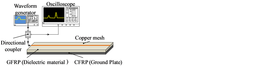
Figure 1. Schematic representation of self-sensing single-line TDR method for damage detection of a CFRP laminate.
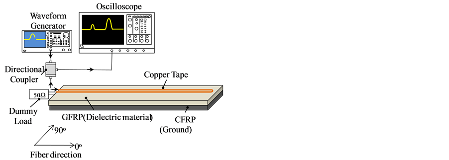
Figure 2. Schematic representation of self-sensing curved TDR method for damage detection of a CFRP laminate.
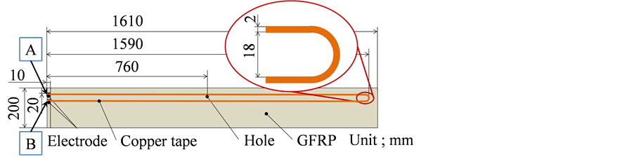
Figure 3. Specimen configuration.
/0/−45/90]S. The material used to fabricate the CFRP laminate is Toray T800S/3900-2B prepreg (180˚C × 2 hr × 0.59 MPa). After fabricating the CFRP laminate of 1600 mm length, a GFRP laminate of 1 mm thickness (1590 mm length and 200 mm width) is attached on the CFRP laminate as dielectric material using epoxy adhesive. For a transmission line, a couple of conductive material is required. For the another conductive material, copper tape of 2 mm width (0.025 mm thickness) is used to make a curved MSL. The impedance of the MSL is 49.6 Ω, which is calculated with the formulas shown in the reference [18] . At the curved part of the transmission line, copper plate of the same thickness is used and connected with soldering as shown in Figure 4. As mentioned before, the spacing between the two lines must be four times larger than the width of the strip. In the present study, therefore, the inner diameter of the curved part is 9 mm.
To obtain the low electrical contact resistance at the input terminal of the CFRP laminate, an electric copper plating method is used [23] . At the input end of the transmission line, the CFRP laminate is used as electric ground and the copper strip is used as a signal line. The experimental set up is shown in Figure 2. A function generator AFG3251 made by Tektronix Inc. (1 ch, Max 240 MHz) is used to generate pulse signal. The pulse wave is shown in Figure 5: the amplitude is 5 V and the half-band wise is 4 ns. Although the amplitude of the generated signal is 5 V, the amplitude of the input signal is almost 1 V because of the mismatch between the coaxial cable and the self-sensing transmission line. A directional coupler of ZFDC-10-5 (Mini-Circuit) is adopted to select pulse signal wave reflected from the specimen. To measure the reflected pulse signal, oscilloscope TDS5034B (Tektronix, sampling 0.02 ns) is used. Copper mesh strip of 0.16 mm thickness (wire diameter is 0.08 mm, equivalent conductance that is calculated from the volume fraction is 1.5 × 10⁷ S/m).
As damage, a mechanical hole is made using a drill of 6 mm diameter at the 760 mm distance from the input end as shown in Figure 3. The edge of the hole is 1 mm distance from the copper strip line edge as shown in Figure 6. This is named type A damage in the present study. After measurements, the drill hole was extended to the edge of the copper strip using filing as shown in Figure 7. This is named type B damage. These two types of model damage are experimentally investigated.
4. Results and Discussion
Figure 8 shows the measured results of reflected signal without damage. The abscissa is the time and the ordinate is the measured voltage of the reflected signal. The input arrow means the position of the end of the time zone affected by the input terminal. The end arrow means the position of the start of the time zone affected by the end terminal. The time zone between the input arrow and the end arrow is, therefore, the measured gage area. The curve arrow means the location of the curve that is calculated from the time difference. Although the radius of the curved strip is four times larger than the width of the copper strip, the small refection is observed at the start point and the end point of the curved copper strip. The both reflection from the start point and the end point of the curved copper strip means that the signal is reflected at the soldering point as shown in Figure 4. As there is no signal reflection at the middle in the curved point, it is understood that the electrical resistance difference between the fiber direction and the transverse direction at the CFRP surface does not affect the TDR method. When a perfectly connected curved MSL is used, the curved MSL is effective for damage detection.
Figure 9 shows the measured results of the type A damage. The abscissa is the time and the ordinate is the voltage difference between the intact result shown in Figure 8 and the results with type A damage. As shown in Figure 8, there are many noise reflected signals, and the reflected signal from the damage is not clearly observed.
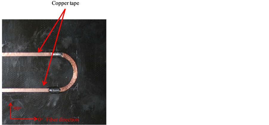
Figure 4. Curved part of the transmission line.

Figure 5. Typical example of input signal.
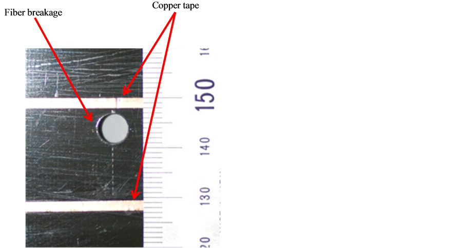
Figure 6. Fiber breakage (type A) using a drill hole of 6 mm diameter.
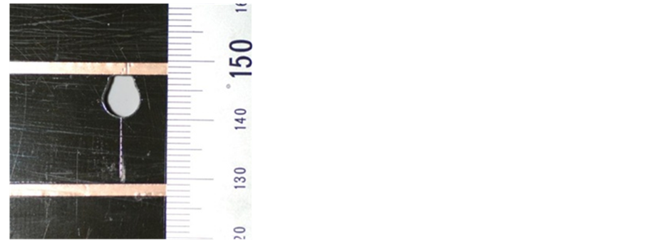
Figure 7. Extended fiber (type B) breakage using filing.

Figure 8. Measured reflected pulse signal from the curved MSL without damage.

Figure 9. Measured reflected pulse signal difference from the curved MSL with damage type A.
Figure 10 shows the measured results of the type B damage. The abscissa and the ordinate are the same as those of Figure 9. At the damage expected point, the clear reflected signal is observed as shown in Figure 10. This indicates that the damage closed to the copper strip line can be detected by using the self-sensing curved MSL method.
Table 1 shows the calculated results of the velocity of transmission wave and accuracy of damage location detection from the self-sensing curved MSL method. The method has good performance for finding damage closed to the copper strip line. It is, however, difficult to find damage far from the copper strip line as shown in Figure 9. When the damage is apart by the distance of the thickness of dielectric material, the damage is not detected. This is because the electro-magnetic wave energy is kept between the two conductive materials, and the leaked wave energy is almost equal to the distance of the thickness of dielectric material.
The limit distance of the damage detection should be carefully investigated after clarification of the effect of a CFRP laminate at the high frequency signal: difference materials of different conductance are stacked in a laminate. This must be our future work.
5. Conclusions
The present study deals with a self-sensing curved MSL method to detect damage of a CFRP laminate. To investigate the effect of orthotropic electric conductance for the curved MSL, experimental studies are performed. Fiber breakage damage of a drilled hole is detected using the self-sensing curved MSL. Results obtained are as follows:
1) The effect of orthotropic conductance at the curved strip line is negligible. Using the self-sensing curved MSL method, wide area of the CFRP surface is investigated compared with the single MSL method.
2) Fiber breakage that locates closed to the copper strip line can be detected by the self-sensing curved MSL method.
3) It is difficult to detect damage far from the copper strip line.
Acknowledgements
The present research is supported by AOARD-124043. The authors thank Dr. Les Lee at AFOSR for their valuable comments and suggestions. Finally, we would like to thank the AOARD for a grant that made it possible to

Figure 10. Measured reflected pulse signal difference from the curved MSL with damage type B.

Table 1. Estimated result of damage location.
complete this research.
References
- Schulte, K. and Baron, Ch. (1989) Load and Failure Analyses of CFRP Laminates by Means of Electrical Resistively Measurements. Composite Science and Technology, 36, 63-76.
http://dx.doi.org/10.1016/0266-3538(89)90016-X - Muto, N., Yanagida, H., Nakatsuji, T., Sugita, M. and Ohtsuka, Y. (1993) Preventing Fatal Fractures in Carbon-Fibre-Glass-Fibre-Reinforced Plastic Composites by Monitoring Change in Electrical Resistance. Journal of the American Ceramic Society, 76, 875-879. http://dx.doi.org/10.1111/j.1151-2916.1993.tb05309.x
- Chen, P.W. and Chung, D.D.L. (1993) Carbon Fiber Reinforced Concrete for Smart Structures Capable of Non-Destructive Flaw Detection. Smart Materials and Structures, 2, 22-30.
- Kaddoour, A.S., Al-Salehi F.A. and Al-Hassani, S.T.S. (1994) Electrical Resistance Measurement Technique for Detecting Failure in CFRP Materials at High Strain Rate. Composites Science and Technology, 51, 377-385. http://dx.doi.org/10.1016/0266-3538(94)90107-4
- Irving, P.E. and Thiagarajan, C. (1998) Fatigue Damage Characterization in Carbon Fibre Composite Materials Using an Electric Potential Technique. Smart Materials and Structures, 7, 456-466.
http://dx.doi.org/10.1088/0964-1726/7/4/004 - Abry, J.C., Bochard, S., Chateauminois, A., Salvia, M. and Giraud, G. (1999) In Situ Detection of Damage in CFRP Laminates by Electric Resistance Measurements. Composites Science and Technology, 59, 925-935. http://dx.doi.org/10.1016/S0266-3538(98)00132-8
- Seo, D.C. and Lee, J.J. (1999) Damage Detection of CFRP Laminates Using Electrical Resistance Measurement and Neural Network. Composite Structures, 47, 525-530.
http://dx.doi.org/10.1016/S0263-8223(00)00016-7 - Todoroki, A., Tanaka, M. and Shimamura, Y. (2002) Measurement of Orthotropic Electric Conductance of CFRP Laminates and Analysis of the Effect on Delamination Monitoring with an Electric Resistance Change Method. Composites Science and Technology, 62, 619-628.
- Todoroki, A. and Tanaka, Y. (2002) Delamination Identification of Cross-Ply Graphite/Epoxy Composite Beams Using Electric Resistance Change Method. Composites Science and Technology, 62, 629-639. http://dx.doi.org/10.1016/S0266-3538(02)00013-1
- Ogi, K. and Takao, Y. (2005) Characterization of Piezoresistance Behavior in a CFRP Unidirectional Laminate. Composites Science and Technology, 65, 231-239.
http://dx.doi.org/10.1016/j.compscitech.2004.07.005 - Selvakumaran, L. and Lubineau, G. (2014) Electrical Behavior of Laminated Composites with Intralaminar Degradation: A Comprehensive Micro-Meso Homogenization Procedure. Composite Structure, 109, 178-188. http://dx.doi.org/10.1016/j.compstruct.2013.10.057
- Todoroki, A., Haruyama, D., Mizutani, Y., Suzuki, Y. and Yasuoka, T. (2014) Electrical Resistance Change of Carbon/Epoxy Composite Laminates under Cyclic Loading under Damage Initiation Limit. Open Journal of Composite Materials, 4, 22-31. http://dx.doi.org/10.4236/ojcm.2014.41003
- Chen, G.D., Sun, S.S., Pommerenke, D., Drewniak, J.L., Greene, G.G., McDaniel, R.D., Belarbi, A. and Mu, H.M. (2005) Crack Detection of a Full-Scale Reinforced Concrete Girder with a Distributed Cable Sensor. Smart Materials and Structures, 14, S88-S97. http://dx.doi.org/10.1088/0964-1726/14/3/011
- Lin, M.W., Thaduri, J. and Abatan, A.O. (2005) Development of an Electrical Time Domain Reflectometry (ETDR) Distributed Strain Sensor. Measurement Science and Technology, 16, 1495-1505. http://dx.doi.org/10.1088/0957-0233/16/7/012
- Obaid, A.A., Yarlagadda, S., Yoon, M.K., Hager, N.E. and Domszy, R.C. (2006) A Time-Domain Reflectometry Method for Automated Measurement of Crack Propagation in Composites during Mode I DCB Testing. Journal of Composite Materials, 40, 2047-2066.
http://dx.doi.org/10.1177/0021998306061309 - Korokawa, H., Todoroki, A. and Mizutani, Y. (2012) Damage Monitoring of CFRP Plate Using Self-Sensing TDR Method. Journal of Solid Mechanics and Materials Engineering, 6, 1053-1061. http://dx.doi.org/10.1299/jmmp.6.1053
- Korokawa, H., Todoroki, A. and Mizutani, Y. (2012) Numerical Simulation of Self-Sensing Time Domain Reflectometry for Damage Detection of Carbon Fiber Reinforced Polymer Plate. Journal of Solid Mechanics and Materials Engineering, 6, 1062-1071. http://dx.doi.org/10.1299/jmmp.6.1062
- Todoroki, A., Kurokawa, H., Mizutani, Y., Matsuzaki, R. and Yasuoka, T. (2014) Self-Sensing Time Domain Reflectometry Method for Damage Monitoring of a CFRP Plate Using a Narrow-Strip Transmission Line. Composites Part B: Engineering, 58, 59-65.
http://dx.doi.org/10.1016/j.compositesb.2013.10.047 - Todoroki, A., Suzuki, K., Mizutani, Y. and Matsuzaki, R. (2010) Durability Estimates of Copper Plated Electrodes for Self-Sensing CFRP Composites. Journal of Solid Mechanics and Materials Engineering, 4, 610-620. http://dx.doi.org/10.1299/jmmp.4.610
- Wheeler, H.A. (1978) Transmission-Line Properties of a Strip Line Between Parallel Planes. IEEE Transactions on Microwave Theory and Techniques, 26, 866-876.
http://dx.doi.org/10.1109/TMTT.1978.1129505 - Wadell, B.C. (1991) Transmission Line Design Handbook. Artech House Inc., Norwood, 298-299.
- Hirano, Y., Katsumata, S., Iwahori, Y. and Todoroki, A. (2010) Artificial Lightning Testing on Graphite/Epoxy Composite Laminate. Composites Part A: Applied Science and Manufacturing, 41, 1461-1470. http://dx.doi.org/10.1016/j.compositesa.2010.06.008
- Todoroki, A., Suzuki, K., Mizutani, Y. and Matsuzaki, R. (2010) Electrical Resistance Change of CFRP under Compression Load. Journal of Solid Mechanics and Materials Engineering, 4, 864-874. http://dx.doi.org/10.1299/jmmp.4.864
NOTES

*Self-sensing curved MSL.