Journal of Power and Energy Engineering
Vol.07 No.06(2019), Article ID:92877,11 pages
10.4236/jpee.2019.76001
Electrostatic Charge Generation in Pneumatic Conveying Process: Effect of Particle Properties
Manoochehr Fathollahi1*, Mohammad Eghbal Ahmadi2, Seyed Mohammad Javad Hosseini1
1Department of Material and Manufacturing Technologies, Malek Ashtar University of Technology, Tehran, Iran
2Department of Chemical and Petroleum Engineering, Sharif University of Technology, Tehran, Iran

Copyright © 2019 by author(s) and Scientific Research Publishing Inc.
This work is licensed under the Creative Commons Attribution International License (CC BY 4.0).
http://creativecommons.org/licenses/by/4.0/


Received: February 26, 2019; Accepted: June 1, 2019; Published: June 4, 2019
ABSTRACT
One of the main concerns in particle pneumatic conveying process is the possibility of hazards for operation safety due to the electrostatic charge generation as a result of collisions between particles and the equipment wall. Indeed, the electrostatic discharge can occur in the equipment leading to fire or explosion. Simulation of these kinds of processes plays an important role in understanding the various aspects of the system in order to production loss prevention. This paper deals with the simulation of particle pneumatic conveying process inside an inclined tube using a particular method. In this method, the electrification of particles inside the tube is influenced by the vertical collision velocity against the tube wall. Simulation of the particle movements inside the tube, generation of electrostatic charges over the particle surfaces as well as the possibility of fire as a result of discharging the electrostatic energy are investigated. The possibility of fire is investigated by comparing the amount of electrostatic energy with minimum ignition energy (MIE) of the particles. The effect of particle properties including the size and mechanical ones in the simulation is studied. Finally, several solutions are proposed to manage the risk of fire and explosion. As results, the electrostatic energy (E) is beyond the MIE, and the electrostatic discharge can occur leading to explosion for the diameters more than 2 mm and also for elasticity constants lower than 140 MPa. Eventually, there is no hazard of fire and explosion, since all calculated electrostatic energy for the change of Particle Poisson’s ratio varying from 0.1 to 0.9 is less than the MIE value for the air flow rate of 10 m3/h.
Keywords:
Electrostatics, Pneumatic Conveying, Simulation, Powder Technology, Particle Charge

1. Introduction
One of the common processes in the chemical industry is the pneumatic conveying process. There is always a possible ignition source in such a process for fire and explosion, and thus, a hazard for operation safety in the process industry. Indeed, as a result of collisions between the solid particles and the wall inside the tanks, tubes and other equipment, the electrostatic charge generates over the solid particles surfaces. Afterward, the charged particles are transported, and the electrostatic discharge can occur which sometimes leads to fire and explosion.
One of the least costly and best approaches for understanding these types of risky processes is using process modeling and simulation. Having a complete model of the process in hand, various aspects of the process can be investigated leading to proper and safe design to minimize the risk of hazards.
Several researchers have studied the pneumatic conveying process both numerically and experimentally. Korevaar et al. [1] tried to model a system where the powder is electrically charged by conveying it pneumatically through a square tube. They used the DEM-CFD method to model and solve the system. Lim [2] studied the pneumatic transport of granular materials through a vertical tube in the presence of an electrostatic field. Nwose et al. [3] studied the effects of electrostatic charge on powder flow behavior in die filling both in a vacuum and air condition using a 2D model. Chen et al. [4] investigated the effect of particle degradation due to the high velocity of the fluid in electrostatic properties of the process. They concluded that the particle size reduction and particle number increase have an impact on the flow characteristics and the electrostatic type of the process. In another study done by Qian et al. [5] , the effect of moisture content on the flow is analyzed and the characteristics of measured electrostatic signals from particle flow under different flow conditions were investigated. The accumulation of static electricity during powder transport was investigated experimentally by Schwindt et al. [6] . According to their measurements, the particle charge increases if the conveying air flow rate is increased. Numerical investigation for the simulation of electrostatic charge in particle pneumatic conveying process was also reported by researchers [7] .
In this study, a particular method is used to predict the electrostatic charge generation during the particle movement in the pneumatic conveying process inside an inclined tube. The hydrodynamic model describing the flow behavior of the gas-solid phase is coupled with the equations governing the particle charging phenomenon. In the developed model, it is shown that the calculation of the electrostatic charge over the particles is dominantly affected by the contact area as a result of colliding the particles and inner pipe wall. The equations used in contact mechanic especially those of based on Hertzian theory [8] [9] are efficiently utilized in the model. Numerical methods are used to solve a set of mathematical equations governing the system. Simulation of the particle movements inside the tube, generation of electrostatic charges over the particle surfaces, as well as the possibility of fire as a result of discharging the electrostatic energy is investigated. Furthermore, the effect of important parameters of the particle, including the parameters related to the size as well as mechanical properties is studied.
It is worth underlying that in order to better understand the flow dynamics and electrostatic charging of the particles during the process, the commercially available finite element software COMSOL Multiphysics is used to simulate the motion of charged particles under different operating parameters.
The rest of the paper is organized as follows. In the next section, the developed model focusing on the main governing equations and assumptions are described. The results and discussion about the effect of particle properties are presented in Section 3, while Section 4 concludes the paper.
2. Model Description
At the first step, the outline of the simulation is briefly described in this section. As shown in Figure 1, the particles are discharged from a feeder to the equipment and transport under the influence of the air flow rate. During transportation, the particles collide with the inner side of the tube, and consequently, the particles are electrostatically charged. The electrostatic charges over the particles potentially have electrostatic energy. If the accumulation of electrostatic energy is larger than MIE (minimum ignition energy), the possibility of fire is evaluated. This is all that should be taken into consideration in the modeling and simulation. Note that MIE of a particle is the smallest required electrostatic energy to ignite an optimum concentration of the material using a spark.
The model is developed and then solved to study the variation of two important variables, including the generated electrostatic charges and the electrostatic energy of the particles. The variation of these variables is influenced by several physical phenomena, and thus, the model consists of several differential and algebraic equations, the most important of which are conservation equations and equations related to Hertzian Theory.
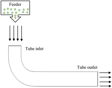
Figure 1. The schematic of the conveying process to be simulated.
At the first step, the equations related to the variation of the fluid and particle velocity are solved. Then, with the particle collision velocities toward the tube wall in hand, those parts of the equations responsible for calculating the electrostatic charges and electrostatic energy come to the solution sequence of the model, and finally the simulation is performed.
The developed Multiphysics model would be too complex without considering some assumptions. The key assumptions and the main mathematical equations governing the model are described in the following.
1) The momentum equations
The turbulent flow regime (Compressible flow with Mach number < 0.3) is assumed. Moreover, it is assumed that particle transferring has no effect on the velocity profiles of the particles in the tube.
The momentum equation of the air flow is as follows:
(1)
where p is the pressure, l is the length, µ is the viscosity, ρ is the density, and F denotes to the forces acting on the fluid. Using the “k-ε” model [10] , the following equations are used for the variation of turbulent kinetic energy (k) and dissipation (ε):
(2)
(3)
where ui the velocity in the corresponding direction is, Eij denotes the rate of deformation and µT is the eddy viscosity. µT is calculated as follows:
(4)
Equations (2) to (4) also consist of some adjustable constants, the values of which have been estimated by numerous iterations of data fitting as follows:
In addition, the particle momentum equation is:
(5)
where mp is the mass of the particle. Moreover, FC, FD, and FG are the contact force (calculated by the particle collision), the drag force and the gravity force, respectively.
The drag coefficient can be calculated by Equation (6).
(6)
Note that the grinding process as a result of the particle-particle collision is neglected.
2) The equations of electrostatic charge (Q) and electrostatic energy (E) of the particles
The magnitude of the particle charge (as a result of particle and tube wall collision) depends upon the nature of the wall and particles, actual contact area, and the speed of particle towards the wall [11] . It is assumed that only the vertical velocity component of the particles determines the impact charging of them. In addition, the contact area between the particle and tube wall is calculated based on Hertzian contact theory as follows:
(7)
Smax is the maximum contact area (Figure 2) calculated according to the following equation:
(8)
In addition, V is the particle velocity, and Vel is the velocity at which the elastic limit is reached. R is the radius of the sphere and rt denotes the radius of the contact area. Pm denotes the mean pressure over the contact area, and ρp is the density of the particle. Furthermore, Ep and Ew are the elasticity constants of the particle and wall. σp and σw are also the Poisson’s ratio of the particle and wall, respectively.
Note that, since the particles are much smaller than the tube diameter, it is assumed that the particles collide with a flat plate instead of the curved plane of the tube wall.
The main goal is to estimate the particle charge generation (Q) and electrostatic energy (E) of the particles. Typically, the charging amount of the particle can be described by its charge density. Having the velocity of each particle in hand and with regard to the contact area of each particle calculated by Equation (7), the Q is estimated using the following equation:
(9)

Figure 2. Particle collision and deformation.
In which, q is the charge density of the particle. Note that the charge density of the particle is the function of its material [12] . The summation of the particle charge over the whole number of particle collisions obtains the total generated electrostatic charges.
For calculating the electrostatic energy, first, the special capacity (C) is calculated by the following equation:
(10)
In which (resistance) can be obtained using the following equation:
(11)
where L is the characteristic length and A denotes to the area of the particles.
Note that the nominator in Equation (10) is indeed the charge relaxation time of the particles defined as follow:
(12)
In the final step, the electrostatic energy can be calculated using the following equation:
(13)
It should be noted that by comparing the electrostatic energy with minimum ignition energy (MIE) of the particles, the possibility of fire can be evaluated.
3. Results and Discussion
For conditions presented in Table 1, the simulation is performed to predict the behavior of the developed model of the particle pneumatic conveying process. In the simulation, the initial air flow rate is 10 m3/s, the air pressure at the outlet is 1.013 × 10⁵ Pa, the initial values of the velocity of the particles are all zero and the tube wall is stationary. Moreover, the particle number transporting into the tube form the feeder is considered 500. The tube wall material is Stainless Steel 360 and the properties of which are utilized in the equations. The analysis of the effect of particle diameter, particle Poisson’s ratio and the particle elasticity constant on the simulation is performed, and the results are presented in next sub-sections.

Table 1. Simulation condition.
Finite element method is used as the numerical solution in this paper. Three-dimensional meshes are created for finite element analysis. Non-uniform meshing is applied to improve the computational efficiency, where the mesh is fine for great changes of variables, elsewhere the mesh is larger (Figure 3).
Note that the MIE is not a fixed value and is influenced by the gas phase condition like moisture content and the presence of flammable vapor. These factors are kept constant in the simulation.
It is worth underlying that the simulation is in dynamic mode, and the variables are the function of both time and the location. In fact, all the variables are changing dynamically and have different values at each time and each position along the tube. Accordingly, only the maximum values of the electrostatic charge and electrostatic energy in each case (which indeed are the worst condition) are shown, that can be considered as the basis of the safe design.
3.1. Effect of the Particle Diameter
As the first scenario, the effect of particle diameter is studied. Figure 4 presents the results.
As depicted, by increasing the particle diameter, the amount of particle charges enhances due to the possibility of increasing the contact area of the particles colliding with the tube wall. For the diameters more than 2 mm, the electrostatic energy (E) is beyond the MIE, and the electrostatic discharge can occur leading to fire or explosion. One solution to manage the risk of fire and explosion can be a reduction in the volumetric flow of air leading to reduction in particle velocity, which in turn, decreases the particle electrostatic charge.
3.2. Effect of the Elasticity Constant of the Particle
As the second scenario, the elasticity constant of the particles is increased linearly, and its effect is studied (Figure 5). The elasticity constant shows the ability of the particle to resist a distorting influence and to return to its original size and shape when collides the inner pipe wall.
The higher values of the elasticity constants mean the higher stiffness of the particle. The more the stiffness of the particles, the less the contact area after the collision of particles and pipe wall is made. Accordingly, as shown in Figure 5, increasing the elasticity constant of the particles leads to the reduction in electrostatic charge generation over the particles, yet not linearly. As depicted, for elasticity constants lower than 140 MPa the electrostatic energy is more than MIE, and the possibility of fire is high. Decreasing the air flow rate or the particle size can be two solutions for reducing the risk of fire and explosion. In other words, in the case of using the particles with the elasticity constants lower than 140 MPa, it is better to use a smaller size of particles in order to have a safer pneumatic conveying process.
Quantitatively speaking, the results demonstrate that an increase of elasticity constant by near 500%, causes an about 100% reduction to particle electrostatic charge (for the range of values considered herein).
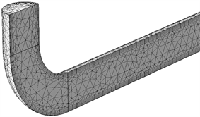
Figure 3. Meshing scheme of the tube.
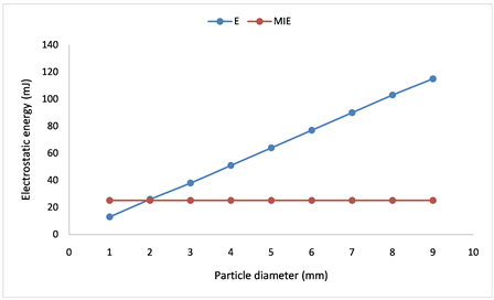

Figure 4. The effect of particle diameter.

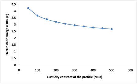
Figure 5. The effect of elasticity constant (stiffness of the particle).
3.3. Effect of the Particle’ Poisson Ratio
As the final scenario, we focused on the influence of particle Poisson’s ratio. Accordingly, the particle Poisson’s ratio is left to vary while other parameters of the simulation are kept constant. The simulation is performed for an air flow rate of 10 m3/h.
As shown in the results, it can be concluded that the particle Poisson’s ratio plays an important role in charge generation over the surface of particles inside the tube. The increase of Poisson’s ratio leads to the reduction of particle electrostatic charge generation. For the air flow rate of 10 m3/h, there is no hazard of fire and explosion, since all calculated electrostatic energy for the change of Particle Poisson’s ratio varying from 0.1 to 0.9 is less than the MIE value. However, this is mainly due to the low value of the air flow rate. As shown in Figure 6, by increasing the air flow rate from 10 to 30 m3/h, there is a hazard of electrostatic discharge for Poisson’s ratios less than 0.7. When working with high air flow rate and with the particles with low Poisson’s ratios, reduction in the size or the number of the particles may reduce the risk of fire and explosion.
4. Conclusions
This work dealt with the simulation of particle pneumatic conveying process inside an inclined tube, focusing on prediction of electrostatic charge generation over the particles in various conditions.
In the developed model, the velocity of the particles inside the tube was obtained in the first step. Then, using the Hertzian contact theory, the contact area as a result of the collision between the particles and the pipe wall was calculated. Having calculated the contact area, the amount of charge of the particles at a single collision was calculated regarding the charge density of the particles. Afterward, the electrostatic energies of the particles as a result of the accumulation of the electrostatic charge were estimated. By comparing the amount of electrostatic energy with MIE of the particles, the possibility of the fire was studied. Finally, the effect of important parameters on the generation of particle charge, the
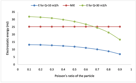
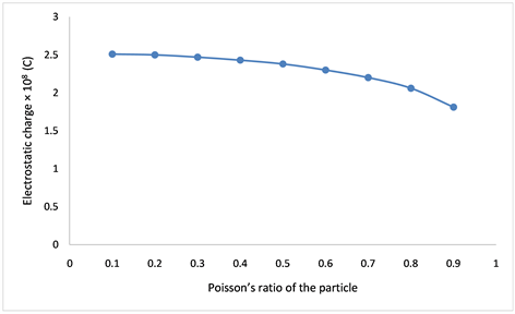
Figure 6. The effect of particle Poisson’s ratio.
amount of electrostatic energy as well as the possibility of fire and explosion were studied. It was shown that by increasing the particle diameter, the electrostatic energy was linearly increased. On the other hand, the linear increase in the stiffness of the particles brings about the reduction of electrostatic charge generation. Indeed, the particles with higher stiffness had less contact area when colliding with the pipe wall, and consequently less generated values of electrostatic charge.
As results, for the diameters more than 2 mm, the electrostatic energy (E) is beyond the MIE, and the electrostatic discharge can occur leading to fire or explosion. Also, for elasticity constants lower than 140 MPa the electrostatic energy is more than MIE, and the possibility of fire is high. Also, for the air flow rate of 10 m3/h, there is no hazard of fire and explosion, since all calculated electrostatic energy for the change of Particle Poisson’s ratio varying from 0.1 to 0.9 is less than the MIE value. However, by increasing the air flow rate from 10 to 30 m3/h, there is a hazard of electrostatic discharge for Poisson’s ratios less than 0.7. Finally, when working with high air flow rate and with the particles with low Poisson’s ratios, reduction in the size or the number of the particles may reduce the risk of fire and explosion.
Conflicts of Interest
The authors declare no conflicts of interest regarding the publication of this paper.
Cite this paper
Fathollahi, M., Ahmadi, M.E. and Hosseini, S.M.J. (2019) Electrostatic Charge Generation in Pneumatic Conveying Process: Effect of Particle Properties. Journal of Power and Energy Engineering, 7, 1-11. https://doi.org/10.4236/jpee.2019.76001
References
- 1. Korevaar, M.W., Padding, J.T., Van Der Hoef, M.A. and Kuipers, J.A.M. (2013) Modeling of Tribo-Electrification of a Pneumatically Conveyed Powder in a Squared Duct Using DEM-CFD. Proceeding 2013 Annual Meeting of the Electrostatics Society of America, Cocoa Beach, 11-13 June 2013, E3-1-15.
- 2. Lim, E.W.C., Zhang, Y. and Wang, C.H. (2006) Effects of an Electrostatic Field in Pneumatic Conveying of Granular Materials through Inclined and Vertical Pipes. Chemical Engineering Science, 61, 7889-7908. https://doi.org/10.1016/j.ces.2006.07.045
- 3. Nwose, E.N., Pei, C. and Wu, C.Y. (2012) Modelling Die Filling with Charged Particles Using DEM/CFD. Particuology, 10, 229-235. https://doi.org/10.1016/j.partic.2011.11.010
- 4. Chen, W., Zhang, J., Donohue, T., Williams, K., Cheng, R., Jones, M. and Zhou, B. (2017) Effect of Particle Degradation on Electrostatic Sensor Measurements and Flow Characteristics in Dilute Pneumatic Conveying. Particuology, 33, 73-79. https://doi.org/10.1016/j.partic.2016.10.004
- 5. Qian, X., Shi, D., Yan, Y., Zhang, W. and Li, G. (2017) Effects of Moisture Content on Electrostatic Sensing Based Mass Flow Measurement of Pneumatically Conveyed Particles. Powder Technology, 311, 579-588. https://doi.org/10.1016/j.powtec.2016.12.061
- 6. Schwindt, N., von Pidoll, U., Markus, D., Klausmeyer, U., Papalexandris, M.V. and Grosshans, H. (2017) Measurement of Electrostatic Charging during Pneumatic Conveying of Powders. Journal of Loss Prevention in the Process Industries, 49, 461-471. https://doi.org/10.1016/j.jlp.2017.05.028
- 7. Grosshans, H. and Papalexandris, M.V. (2017) Numerical Study of the Influence of the Powder and Pipe Properties on Electrical Charging during Pneumatic Conveying. Powder Technology, 315, 227-235. https://doi.org/10.1016/j.powtec.2017.04.012
- 8. Adams, G.G. and Nosonovsky, M. (2000) Contact Modeling—Forces. Tribology International, 33, 431-442. https://doi.org/10.1016/S0301-679X(00)00063-3
- 9. Wriggers, P. (2006) Computational Contact Mechanics. Springer, Berlin. https://doi.org/10.1007/978-3-540-32609-0
- 10. Launder, B.E. and Spalding, D.B. (1974) The Numerical Computation of Turbulent Flows. Computer Methods in Applied Mechanics and Engineering, 3, 269-289. https://doi.org/10.1016/0045-7825(74)90029-2
- 11. Matsusaka, S. and Masuda, H. (2003) Electrostatics of Particles. Advanced Powder Technology, 14, 143-166. https://doi.org/10.1163/156855203763593958
- 12. Masui, N. and Murata, Y. (1983) Electrification of Polymer Particles by Impact on a Metal Plate. Japanese Journal of Applied Physics, 22, 1057. https://doi.org/10.1143/JJAP.22.1057