Journal of Power and Energy Engineering
Vol.06 No.11(2018), Article ID:88332,11 pages
10.4236/jpee.2018.611001
Parameter Analysis and Numerical Simulation of Hydrogen Production by Steam Reforming of Dimethyl Ether
Lei Guo*, Cong Li
School of Mechanical and Automotive Engineering, Shanghai University of Engineering Science, Shanghai, China

Copyright © 2018 by authors and Scientific Research Publishing Inc.
This work is licensed under the Creative Commons Attribution International License (CC BY 4.0).
http://creativecommons.org/licenses/by/4.0/


Received: October 24, 2018; Accepted: November 4, 2018; Published: November 7, 2018
ABSTRACT
Hydrogen production through dimethyl ether steam reforming is an attractive option for mobile applications of hydrogen fuel cells. Hydrogen is a major trend in the future of energy development. It is not only pollution-free, but also has a high energy density. Therefore, research on hydrogen fuel cells is particularly important. In this paper, a numerical research on dimethyl ether steam reforming reaction in a reactor has been presented using a computational fluid dynamics. A three-dimensional reactor model developed by the commercial software COMSOL (version 5.2a) was used to simulate the reaction characteristics by modifying reforming conditions. The simulation results indicate the temperature distribution, mass distribution, and reveal the dependency of dimethyl ether reforming reaction rate on temperature, pressure, the length of the reactor. The yield of H2 and conversion of dimethyl ether with different mass ratios and inlet temperature (200˚C, 300˚C, 400˚C, 500˚C) were examined. The governing equations in the model include conservations of mass, momentum, energy and chemical species.
Keywords:
Dimethyl Ether, Steam Reforming, Computational Fluid Dynamics Modeling, Simulation

1. Introduction
As a result of rapid consumption of non-renewable energy, hydrogen is a fuel that is regarded as having the most development potential for this century because of its clean, efficient, and renewable characteristics. As a new type of portable power supply, hydrogen is the ideal fuel for PEMFC [1] [2] [3] . Among the various hydrocarbon feeds, for the advantages of high energy density, non-toxicity, easy availability, safe storage, dimethyl ether (DME) is considered to be one of the ideal sources of hydrogen for FCV [4] .
Several studies on kinetic models of DME steam reforming and steam reforming (SR) reaction have been presented [5] . Feng et al. [6] presented a kinetic rate of total combustion of DME based on copper-based catalyst. Seunghyeon Choi et al. investigated the DME ATR reaction with different types of precious metal (Pt, Rh, Ru)-supported CGO catalysts [7] . Derek Creaser et al. developed a global kinetic model for the autothermal reforming of dimethyl ether (DME) over a Pd-Zn/Al2O3 catalyst on a cordierite monolith [8] . M.H. Akbari et al. presented a numerical investigation of catalytic autothermal reforming of methane in a surface microreactor [9] . Francis A. Elewuwa et al. presented a computational parametric analysis of DME steam reforming in a large scale Circulating Fluidized Bed (CFB) reactor [10] [11] . Chang-Feng Yan et al. designed a micro-reactor with catalyst coated on nickel foam support to enhance the heat and mass transfer during dimethyl ether (DME) steam reforming, and investigated the effect of Cr promoter on performance of steam reforming of dimethyl ether in a metal foammicro-reactor [12] [13] . Manoj Kumar Moharana developed an ethanol-based distributed hydrogen production device of the order of 1 kW using steam reforming of ethanol [14] .
In this paper, a simpler kinetic equation was used to replace the previous complex kinetic equations to better describe and analyze the reaction mechanism of hydrogen production from dimethyl ether steam reforming, a three-dimensional SR reactor model was developed to investigate the influence of variation parameters on the performance of reactor. The effects of temperature of reactant gas, steam to DME ratio on the hydrogen production of outlet, DME conversion and average outlet temperature of reformer bed were analyzed.
2. Numerical Model
2.1. Model
The simulated reactor consists of following dimensions: catalytic bed, insulating jacket. There formation chemistry occurs in a catalytic bed, and the reactant gas flow through the inlet of the reactor. The reactor had a diameter of 30 mm and a length of 150 mm.
2.2. Model Assumptions
The reaction flow was assumed to be steady, laminar and incompressible. The gas mixture was supposed to be an ideal gas. The mixture consists of six species: DME, CO, H2, CO2 and H2O. A three-dimensional model has been constructed end used in this analysis.
2.3. Governing Equations
The governing equations are set up on the basis of ideal gas mixture, including the conservations of mass, momentum, energy and chemical species.
The flow of gaseous species through the reformer bed is described by Darcy’s Law [15]
(1)
In the above equation, ρ denotes the gas density, η is the viscosity, κ is the permeability of the porous medium, and Psr is the pressure in the reformer bed.
The equation [15] for the average temperature distribution in the porous bed is given by
(2)
The volumetric heat capacity of the bed is expressed as follows [15]
(3)
Here, the indices “f” and “s” denote fluid and solid phases, respectively, and ε is the volume fraction of the fluid phase. Furthermore, Tsr is the temperature and ksr is the thermal dispersion of the reformer bed. Q represents a heat source, and u is the fluid velocity.
The mass-balance equations [15] for the model are the Maxwell-Stefan diffusion and convection equations at steady state as
(4)
In the equation above, ρ denotes the density, ωi is the mass fraction of species i, xj is the molar fraction of species j, Dij is the ij component of the multicomponent Fick diffusivity. Di denotes the generalized thermal diffusion coefficient, T is the temperature, and Ri is the reaction rate.
2.4. Chemical Kinetics
Steam reforming of DME involves many reactions with different rates, in this paper, following reactions are analyzed:
DME hydrolysis
(5)
MeOH steam reforming
(6)
Water gas shift
(7)
In this paper, the kinetic models of total DME reforming reactions used in this study are given as follows
1) Dimethyl ether hydrolysis into methanol
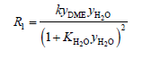 (8)
(8)
where, y was the mole fraction, k was the rate constant.
2) Methanol steam reforming reaction
(9)
where, was catalyst density, was the reforming rate constant, was the molar concentration of methanol, was porosity.
3) Water-gas shift
(10)
where, and were the rate constant and the equilibrium constant of the WGS reaction.
For the reaction of DME hydrolysis, the rate constant K can be calculated by Arrhenius equation as follows.
(11)
To avoid correlation between the pre-exponential factors and activation energies of the Arrhenius equation, the rate constant k at an average temperature T of 300˚C and the activation energy were used as fitting parameters. Thus, for parameter fitting purposes, the Arrhenius equation was reformulated, equation is as follows
(12)
The calculation of A is given by
(13)
The formula of adsorption equilibrium constant is as follows
(14)
where is adsorption enthalpy, Kmj was the adsorption equilibrium constant at the average temperature.
2.5. Boundary Conditions
The inlet and outlet boundary conditions describe a pressure drop across the bed. All other boundaries are impervious, corresponding to the condition [15]
(15)
Convective heat transport at the outlet is assumed to be dominant [15]
(16)
At the outlet, the convective flux condition is used [15] :
(17)
3. Solution Method
In order to solve the non-linear equations, a computational fluid dynamics (CFD) code was developed based on the finite volume method using the SIMPLE algorithm for the coupling of pressure and velocity domains. As is shown in Figure 1, the simulated fluidized porous zone is 0.15 m in length and 0.033 m in radius. The shell is 0.003 m in thickness. The maximum element size is 0.015 m, and minimum element size is 0.0075 m.
4. Results and Discussion
4.1. Experiment and Validation
To verify the availability of the simulation model, an experiment for DME autothermal reforming was set up. The system was shown in Figure 2, the water measured by the metering pump is fully vaporized in the evaporator, and the air, DME and water were preheated to 500 degrees. Then, the mixed gas flowed into the reactor through a mass flow controller, and the reactor was filled with a CuO/ZnO/Al2O3 + ZSM5 catalyst. Finally, the reactants and products flowed into gas chromatography (GC-9900) linked to a computer so as to measure components.
The most important performance indexes of dimethyl ether reforming reaction mainly include dimethylether conversion rate, production rate of hydrogen. The DME conversion and the hydrogen yield are defined as follows
DME conversion: (18)
Hydrogen production: (19)
Compared to the experimental reactor, the performance of the reactor used in the simulation is analyzed. The operating conditions are equal to those of simulations. The ratio of steam to DME varied from 1 to 4, the inlet temperature was 773 K. The DME conversion and volume content of H2 were shown in Table 1 and Table 2 respectively. The result of the experiment was approximate to the

Figure 1. Geometry and mesh size of the reactor.

Figure 2. Schematic diagram of experimental.

Table 1. Comparison of experimental and simulated values of DME conversion.
Table 2. Comparison of experimental and simulated values of H2 production.
result of simulation, the lower hydrogen production of experiment was probably due to hydrogen spillover or hydrogen leak. The experiment temperature was lower than the theoretical value may be caused by the incomplete adiabatic, and the wall heat dissipation. The comparison between the data collected by the experiment and the simulation results verified that the present simulation can describe the reforming reaction in details.
4.2. Study of Parameters
In this section, the influence of parameters including H2O/DME molar ratio, the inlet temperature of mixture gas on the reaction rate has been analyzed. The simulation results indicate the temperature distribution of the reactor, DME conversion and hydrogen production of the reforming reaction. The simulation conditions were as follows: the ratio of steam to DME is 3, Figure 3 was the temperature distribution of the reactor. The inlet mixture gas temperature of the reformer bed was 750 K, and decreases along the reaction bed because of the endothermic hydrolysis reaction, finally, the average outlet temperature of reformer bed was 683 K.
The pressure distribution in the reforming reactor is shown in Figure 4. The pressure at the inlet of the reactant is 1.0009 × 10⁵ Pa, and the pressure at the outlet is 1.0001 × 10⁵ Pa. After calculation, the pressure drop loss during the

Figure 3. The temperature distribution of the reactor.

Figure 4. The pressure distribution of the reforming reactor.
reaction is 8 × 10 − 4 Pa, which is much lower than 10% of the pressure drop in the reforming reactor. Since the pressure drop within the system is very low, it is feasible to assume that the gas is ideally incompressible at the beginning of the model establishment.
4.3. Effects of Temperature
Figure 5(a) and Figure 5(b) are simulations performed under the reaction conditions of a water ether molar ratio of 0.75:0.25, a heat pipe inlet flow rate of 10 m/s, and a standard atmospheric pressure, indicating dimethyl ether. The variation of conversion rate and hydrogen yield at different inlet temperatures. The varying temperature values were 573 K, 623 K, and 673 K, respectively. As can be
 (a)
(a) (b)
(b)
Figure 5. DME conversion and Hydrogen production as a function of heat tubes inlet temperature along the axial length: (a) DME conversion (b) Hydrogen production.
seen from Figures 3-5, as the temperature at the inlet of the reactor increases, the conversion of dimethyl ether and the yield of hydrogen are significantly improved. This is due to the hydrogen production of dimethyl ether by steam reforming. Generally, it is an endothermic reaction. Appropriately increasing the inlet temperature is beneficial to increase the forward reaction rate of the reaction, and the reaction proceeds toward the direction of hydrogen production, thereby improving the conversion efficiency of dimethyl ether and the yield of hydrogen.
The water ether molar ratio is a major operating parameter that affects the hydrogen production of dimethyl ether by steam reforming. Figure 6(a) and Figure 6(b) are simulated simulations of the heat pipe inlet flow rate of 10 m/s,
 (a)
(a) (b)
(b)
Figure 6. DME conversion and Hydrogen production as a function of steam to DME ratio (a) DME conversion (b) Hydrogen production.
reforming reaction bed temperature of 673 K, a standard atmospheric pressure, showing dimethyl ether conversion and hydrogen The variation of the yield under different water ether molar ratios (1, 2, 4). It can be clearly seen from the figure that appropriately increasing the ratio of the molar mass of water vapor to dimethyl ether is advantageous for improving the hydrogen production efficiency of the reformer and increasing the conversion rate of dimethyl ether. However, from the principle of chemical reaction, the molar ratio of water ether is not as large as possible. As the molar mass of water vapor increases, the temperature in the reactor will also decrease, because the entire reforming reaction is endothermic. Therefore, there is a great influence on the reaction rate of the positive reaction, which in turn affects the conversion of dimethyl ether and the hydrogen yield.
5. Conclusions
In this study, catalytic steam reforming of DME is simulated using a three-dimensional CFD model. The simulation model introduced in software COMSOL (version 5.2a) can reveal the temperature distributions in the reactor and the hydrogen production and DME conversion properly. On the basis of the model, we investigated the DME SR reaction on different temperatures, various ratios of steam to DME.
The model can accurately describe the reaction mechanism of hydrogen production from dimethyl ether steam reforming. At the same time, the established reaction kinetic equation is simple, but from the simulation results, the dimethyl ether obtained by using this kinetic equation can be seen. Ether conversion and hydrogen yield are relatively low. Therefore, on the basis of the simplicity of the kinetic equation, how to improve the reaction efficiency is the place to be studied in the follow-up work.
Acknowledgements
This work was supported by Natural Science Foundation of China under Grant NO. 51505275.
Conflicts of Interest
The authors declare no conflicts of interest regarding the publication of this paper.
Cite this paper
Guo, L. and Li, C. (2018) Parameter Analysis and Numerical Simulation of Hydrogen Production by Steam Reforming of Dimethyl Ether. Journal of Power and Energy Engineering, 6, 1-11. https://doi.org/10.4236/jpee.2018.611001
References
- 1. Nicoletti, G., Arcuri, N., Bruno, R., et al. (2015) A Technical and Environmental Comparison between Hydrogen and Some Fossil Fuels. Energy Conversion and Management, 89, 205-213. https://doi.org/10.1016/j.enconman.2014.09.057
- 2. Yuan, X.Z., Li, H., Zhang, S.S., Martin, J., Wang, H.J., et al. (2011) A Review of Polymer Electrolyte Membrane Fuel Cell Durability Test Protocols. Journal of Power Sources, 196, 9107-9116. https://doi.org/10.1016/j.jpowsour.2011.07.082
- 3. Isono, T., Suzuki, S., Kaneko, M., et al. (2000) Development of a High-Performance PEFC Module Operated by Reformed Gas. Journal of Power Sources, 86, 269-273. https://doi.org/10.1016/S0378-7753(99)00441-3
- 4. Hoang, D.L. and Chan, S.H. (2004) Modeling of a Catalytic Autothermal Methane Reformer for Fuel Cell Applications. Applied Catalysis A: General, 268, 207-216. https://doi.org/10.1016/j.apcata.2004.03.056
- 5. Li, C., Gao, Y., Wu, C.S., et al. (2015) Modeling and Simulation of Hydrogen Production from Dimethyl Ether Steam Reforming Using Exhaust Gas. International Journal of Energy Research, 39, 1272-1279. https://doi.org/10.1002/er.3330
- 6. Feng, D.M., Wang, Y., Wang, D., Wang, J., et al. (2009) Steam Reforming of Dimethyl Ether over CuO-ZnO-Al2O3-ZrO2 + ZSM-5: A Kinetic Study. Chemical Engineering Journal, 146, 477-485. https://doi.org/10.1016/j.cej.2008.11.005
- 7. Choi, S. and Bae, J. (2016) Autothermal Reforming of Dimethyl Ether with CGO-Based Precious Metal Catalysts. Journal of Power Sources, 307, 351-357. https://doi.org/10.1016/j.jpowsour.2015.12.068
- 8. Creaser, D., Nilsson, M., Pettersson, L.J., Dawody, J., et al. (2010) Kinetic Modeling of Autothermal Reforming of Dimethyl Ether. Industrial & Engineering Chemistry Research, 49, 9712-9719. https://doi.org/10.1021/ie100834v
- 9. Akbari, M.H., Ardakani, A.H.S., Tadbir, M.A., et al. (2011) A Microreactor Modeling, Analysis and Optimization for Methane Autothermal Reforming in Fuel Cell Applications. Chemical Engineering Journal, 166, 1116-1125. https://doi.org/10.1016/j.cej.2010.12.044
- 10. Elewuwa, F.A. and Makkawi, Y.T. (2015) Hydrogen Production by Steam Reforming of DME in a Large Scale CFB Reactor. Part I: Computational Model and Predictions. International Journal of Hydrogen Energy, 40, 15865-15876. ttps://doi.org/10.1016/j.ijhydene.2015.10.050
- 11. Elewuwa, F.A. and Makkawi, Y.T. (2016) A Computational Model of Hydrogen Production by Steam Reforming of Dimethyl Ether in a Large Scale CFB Reactor. Part II: Parametric Analysis. International Journal of Hydrogen Energy, 41, 19819-19828. https://doi.org/10.1016/j.ijhydene.2016.08.072
- 12. Yan, C.F., Ye, W., Guo, C.Q., Huang, S.L., Li, W.B., Luo, W.M., et al. (2014) Numerical Simulation and Experimental Study of Hydrogen Production from Dimethyl Ether Steam Reforming in a micro-Reactor. International Journal of Hydrogen Energy, 39, 18642-18649. https://doi.org/10.1016/j.ijhydene.2014.02.133
- 13. Yan, C.F., Hai, H., Hu, R.R., Guo, C.Q., Huang, S.L., Li, W.B., Wen, Y., et al. (2014) Effect of Cr Promoter on Performance of Steam Reforming of Dimethyl Ether in a Metal Foam Micro-Reactor. International Journal of Hydrogen Energy, 39, 18625-18631. https://doi.org/10.1016/j.ijhydene.2014.02.152
- 14. Moharana, M.K., Peela, N.R., Khandekar, S., Kunzru, D., et al. (2011) Distributed Hydrogen Production from Ethanol in a Microfuel Processor: Issues and Challenges. Renewable and Sustainable Energy Reviews, 15, 524-533. https://doi.org/10.1016/j.rser.2010.08.011
- 15. Gateau, P. (2007) Design of Reactors and Heat Exchange Systems to Optimize a Fuel Cell Reformer. Proceedings of the COMSOL User’s Conference Grenoble.