Journal of Power and Energy Engineering
Vol.2 No.2(2014), Article ID:42758,10 pages DOI:10.4236/jpee.2014.22001
Paralleled DC-DC Power Converters Sliding Mode Control with Dual Stages Design
![]()
Department of Electrical and Computer Engineering, Oakland University, Rochester, Michigan, USA.
Email: bykhasaw@oakland.edu
Copyright © 2014 Bashar Khasawneh et al. This is an open access article distributed under the Creative Commons Attribution License, which permits unrestricted use, distribution, and reproduction in any medium, provided the original work is properly cited. In accordance of the Creative Commons Attribution License all Copyrights © 2014 are reserved for SCIRP and the owner of the intellectual property Bashar Khasawneh et al. All Copyright © 2014 are guarded by law and by SCIRP as a guardian.
Received December 27th, 2013; revised January 27th, 2014; accepted February 4th, 2014
KEYWORDS
DC-DC Converters; Paralleled Converter; DC-DC Control; Efficiency Improvement of DC-DC; Sliding Mode Control (SMC); Hyper Plane Design; Variable Structure Control (VSC)
ABSTRACT
This paper proposes the new cascaded series parallel design for improved dynamic performance of DC-DC buck boost converters by a new Sliding Mode Control (SMC) method. The converter is controlled using Sliding Mode Control method that utilizes the converter’s duty ratio to determine the skidding surface. System modeling and simulation results are presented. The results also showed an improved overall performance over typical PID controller, and there was no overshoot or settling time, tracking the desired output nicely. Improved converter performance and robustness were expected.
1. Introduction
Power electronics is the process and control of the flow of electric energy from a given source to a load in a shape that is optimally suited for its use. Modern electric systems demand high quality, reliable, efficient and light weight power supplies.
Higher power converters, such as the ones used in Electrified Vehicles (EVs) and aircraft power units, are also in increase demand as a result of the green acts taken on by many countries. The improvement in power switching devices such as the IGBTs and MOSFETs made the power electronics more appealing to many applications. Higher switching frequency, higher power capability and improved efficiency are the main reasons for the expanded application [1].
Paralleled DC-DC converters are used in telecommunication industry widely and operated under closed loop control to regulate the output voltage [2]. The nonlinearities of the DC-DC converters are due to interaction among the converter components and the switching nonlinearity behaviors. However, linearized average model is commonly used for converter analysis [3-9]. A drawback of the linearized model is that it cannot predict the dynamics of the converter in a saturation region [2]. For standalone converters, many nonlinear control approaches have been studied and proposed: Lyapunov based controllers [10-13], variable structure controllers VSC [14- 16], feedback linearization method [17] and Fuzzy logic controllers [18]. In [19], the sliding mode control is used and the results are shown for all types of converters (Buck, Boost and Buck-Boost). The results of this type of control where the state space averaging is applied to sliding mode control PWM converters, showed a good result but high ripple content on the buck-boost converter.
For paralleled DC-DC converters control, [2] proposed an Integral Variable Structure Control (IVSC) for N paralleled DC-DC converters. They emphasized that Variable Structure Control was a natural choice since the control and the plant are both discontinuous and have uncertainties. A fuzzy logic controller is proposed in [18] for the master slave concept of the DC-DC control, and the results showed robust and improved performance over classical linear control. In [20], the control is based on a steady-state DC model and a small-signal model, which showed that current sharing can be achieved without a dedicated current sharing controller. [21-43] explored many of the concepts mentioned above and some of the chaotic behaviors of the converters. The papers are added for the readers’ convenience to further explore the concept of the DC-DC converter control and behavior.
In this paper, we will introduce a concept to improve the output quality and simplify the paralleled converters control to a simple single like converter. We will use a Sliding Mode Controller (SMC) with the Variable Structure Surface Design concept developed in [44] to control the converter. A comparison with a PID controller is presented.
2. Modeling of Buck Boost Converter
In this section a model for N paralleled buck boost converters to supply a common load is developed. Figure 1 shows a commonly used buck-boost configuration for paralleled converters supporting a single load.
This paper will introduce a new approach to controlling the converter to reduce the output harmonics and simplify the control to an equivalent of a single converter. First a single converter model is given by the following equations:
 (1)
(1)
 (2)
(2)
The above equations show the model that the first section of the converter associated with, the switch  takes on the values
 . The current is the inductor current associated with the first inductor
  and
and  is the capacitor voltage as a result of the contribution of all other converters. For multi converters the output current
  is the sum of all individual inductor currents and is given by the following equation.
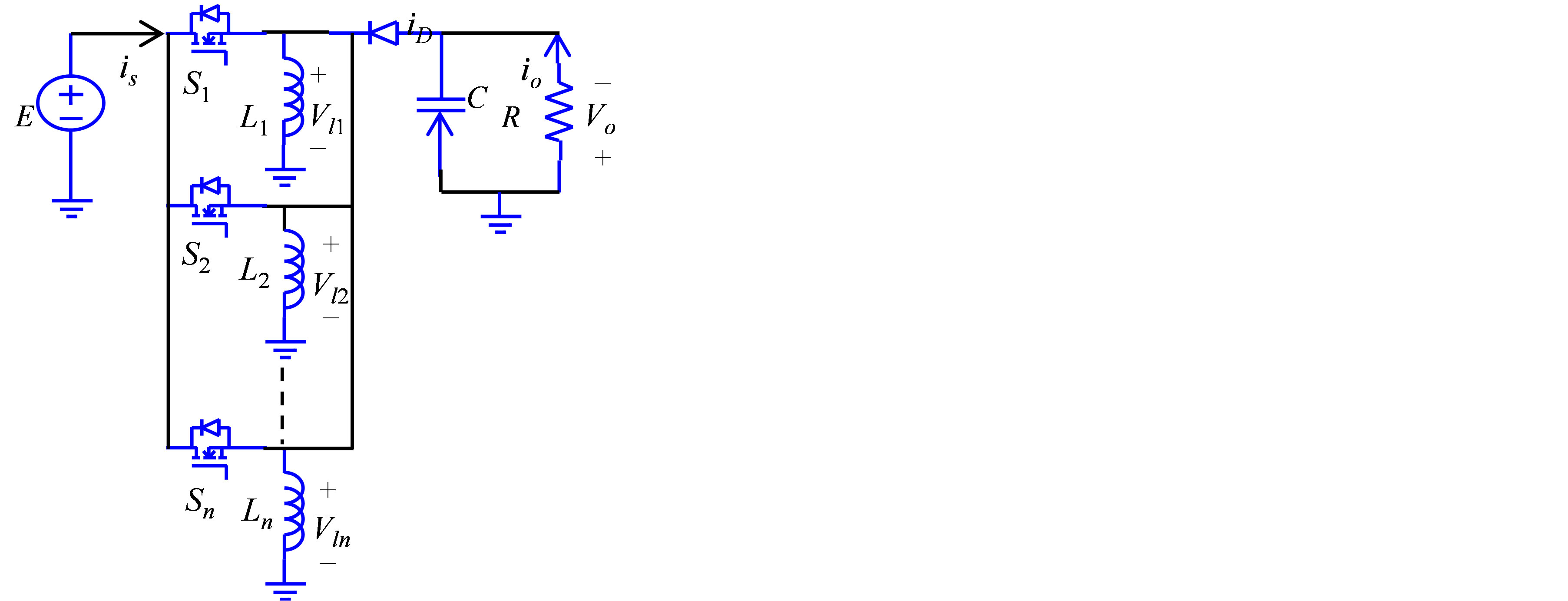
Figure 1. Paralleled buck-boost converter.
 (3)
(3)
The states are the inductor currents and capacitor voltage as shown in Equation (4).
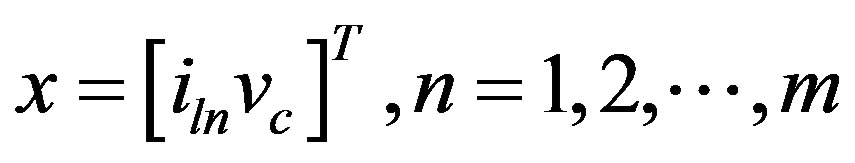 (4)
(4)
m: number of converters Using Equation (3) and based on Equations (1) and (2) we can formulate the following relation. Given that the capacitor voltage is the same as the output voltage .
.
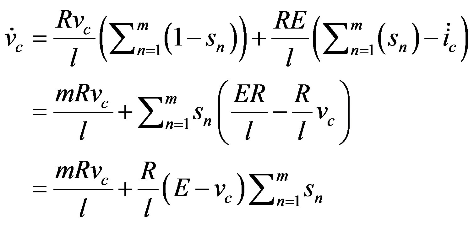
The derivative of the output current given by Equation (3) is shown in Equation (5)
 (5)
(5)
Substituting Equation (1) into Equation (5) and collecting the terms we get Equation (6) interim of the derivative of the load and capacitor currents.
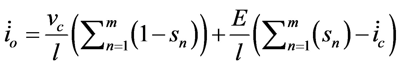 (6)
(6)
where  is the state of the nth switch.
We determine from Figure 1 that the output voltage is equivalent to the capacitor voltage and the relation can be written in Equation (7)
 (7)
(7)
Taking the derivative of Equation (7) we get the following relation
 (8)
(8)
With the advancement in switches and their higher switching frequency capabilities we assume an infinite switching frequency. With this assumption we can assume that the rate of change in the capacitor voltage and current are zero, solving Equation (8) we get the following Equation (9)
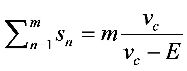 (9)
(9)
It can be seen that the second term of Equation (9) is related to the duty ratio  for the buck boost converter. The duty ration is defined as the turn on time as a percentage of the period defined as
 .
.
 (10)
(10)
Substituting the expression for  into Equation (9) we determine the switching time as follows
 (11)
(11)
The above equation shows the distribution of the switching time for the  converters, the sum of all the switches contribution is equivalent to the duty ratio or the required on time of an equivalent single switch to provide the desired output. The contribution of each leg is an equal portion of the required output voltage and current.
The control methodology can vary from PID, VSC, Fuzzy logic, SMC or other methods, but the end results is the same as to determine the turn ON time for the switches.
Next an improved performance of the converter to reduce harmonics content is presented. It is proposed to do a harmonic cancelation by shifting the switching sequence of the converters, by imposing  on the subsequent converter legs using the following relation
 (12)
(12)
 : Delayed time factor (e.g. 10
 )
)
 : The specific converter
 : Total number of converters
3. Design of the New Converter Control
In this section we propose a new converter control design to simplify the overall control and improve performance. In DC-DC converters control, the principle is to eliminate the error between the actual output and the desired output value. The control action is taking by switching the control device in this case a MOSFET to apply the input DC voltage to the converter periodically and proportional to the error. In this paper we propose separating the converter into two stages as discussed next.
The design consists of two cascaded stages where the first stage is the control stage shown in Figure 2 enclosed by the dashed lines and the second stage called the performance stage.
The performance stage represents m number of parallel converters to be controlled to reduce the harmonics contents of the output. This separation gives the designer the freedom to choose the switching frequency to optimize the performance of the converter. This frequency is

Figure 2. Two stages converter.
independent of the control stage and can be optimized.
The converters switching time is determined in advance and the frequency can be optimized to reduce switching losses or improve EMI performance. The simulation will show the performance of the converter with synchronized switching time and also the enhanced performance with the shifted switching time as suggested above in Equation (12).
The control stage as shown enclosed in the dashed line in Figure 2 is used to control the input voltage to the paralleled converters. In previous converter designs the input voltage always assumed constant and the control was done by switching the converter at variable duty cycles to achieve the desired output values. In this paper we propose the idea of switching the output stage of the converter at an optimal switching frequency and duty cycle while controlling the input stage varying it to achieve the desired output value.
The control of the first stage through , as shown in Figure 3, is designed with the assumption that the parallel converters have an equivalent inductor and capacitor values if the control method requires knowledge of the parameters. The control can be done using, Variable structure Control (VSC), SMC, where parameter sensitivity is not an issue, fuzzy logic, PID or any other method desired by implementation engineers as the problem is reduced to a single converter control.
4. Sliding Mode Control of the Converter
In this section we will use sliding mode control to control the converter. The sliding surface used is a unique duty cycle dependent surface developed in [44]. The controller then derived using the sliding surface coefficients. In [44] a Variable Structure Control (VSC) surface design for DC-DC power converters is presented. The design was done for the Buck boost converter and can be extended and applied to all types using the methodology explained in [44].
Consider the linear time invariant system given by
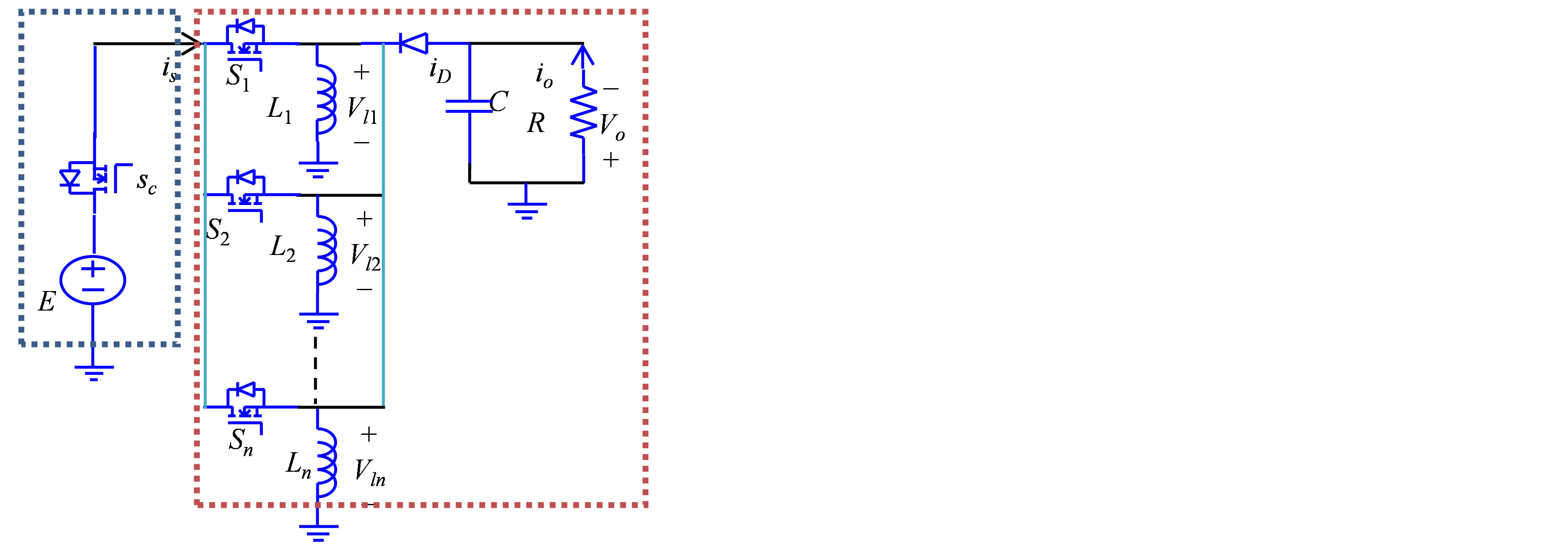
Figure 3. The proposed two stage converter.
Equation (13).
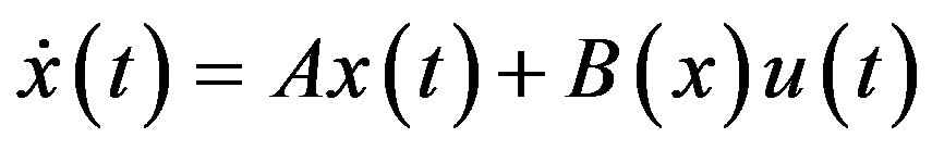 (13)
(13)
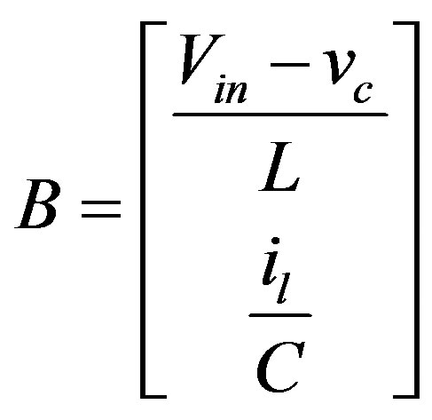
where,
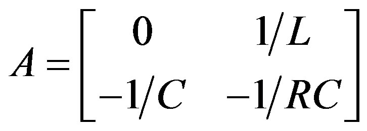 ;
;
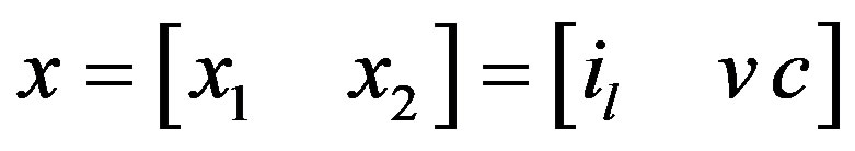
The states are defined as the inductor current and the capacitor voltage which the same as the output voltage.
Given the surface as defined in [14,15].
 (14)
(14)
taking the derivative of (14).
 (15)
(15)
Using Equation (13) to Equation (15) we get the equivalent control discussed by Utkin [16,29]. It is developed to derive the sliding mode equations into the manifold  and then the solution to
  is called the equivalent control
 .
.
 (16)
(16)
The method in [44] defines the surface in term of the duty cycle and the parameters of the DC-DC converters as in Equation (17).
 (17)
(17)
where
Are the errors between the actual values and the desired one. Taking the derivative of Equation (17) we find the value of C, the surface coefficients, as
 (18)
(18)
Using the value of C in Equation (18) and the given A and B coefficients of the system and evaluating Equation (16) to get the equivalent control .
.
 (19)
(19)
The total control of the system consists of two components the equivalent control  and corrective control
 , where the equivalent control is used to reach the surface while the corrective is to keep the system on the surface.
 (20)
(20)
For system stability, we need to guarantee the system ends up and stays at the surface regardless of the initial conditions. Using the following Lyapunov function:
 (21)
(21)
We need to grantee that the derivative of Equation (21) is negative definite that is  for all
 , that from any initial condition. Taking the derivative of (21):
 (22)
(22)
With

and
to grantee Equation (22) holds the corrective control  is chosen as follow.
 (23)
(23)
where  is appositive number. Hence the complete control is given by Equation (20) is:
 (24)
(24)
where  and
and  are the coefficients derived in [2] and given below:

 : Inductor value
 : Capacitor value
 : Load Resistor Value
 : Associated Jordan value associated with the selected eigen values.
 and l: Arbitrary positive numbers
 : Duty ratio In the next section we will show the results of the application of the hyper plane coefficients in the proposed two stage converter and compare to the results to a conventional PID controller. Although a comparison will show an improvement over the conventional method in term of overshoot and settling time, the main purpose of the application to test the feasibility of the method developed in [44] and introduce the proposed two stage converter.
Figure 4 shows a single Buck Boost converter. Figure 5 shows paralleled buck boost converters. Both converters, the single or the paralleled are to regulate the output voltage to a desired value  and provide loads with the desired currents. Figure 6 shows the sliding mode controller as given by (24).
In the next section will show and compare the results of using a single converter, parallel converters, paralleled converters with the enhanced mode and the developed hyper plain coefficients method [44].
5. Results
The converter shown in Figure 4 represent a single Buck Boost converter based on the mathematical model described in (1) and (2). The converter was controlled using a PID control and sliding mode control with the developed hyper plain coefficients and simulated using the following circuit parameters:

In the second part of the simulation, the converters are paralleled and the new two mode design is implemented.
The same values as the single converter are used with a mismatch of 10% to represent a more realistic situation. However for sensitive applications more precise value components can be chosen. Figure 5 shows the converters constructing a paralleled structure for the benefits mentioned earlier in the previous sections. The last part of the simulation was done using the delayed switching time as in (12) to further improve the performance.
First part of the simulation is of the single converters with the values given above. The results are shown below in Figure 7. The second part is the simulation Figure 8 is for the paralleled converter with a fixed duty cycle for all the converters in the performance stage. The third part Figure 9 is the results for the paralleled converters with the proposed switching delay as suggested by Equation (12).
Figure 7 shows the output voltage of a single converter regulated at 80 volts, the output is clearly showing the mount of ripple on the output voltage exceeds 5 V. The increase in the amount of ripples on the system voltage would cause increase losses reducing efficiency and can contribute to the mechanical wear and tear of a system.
Figure 8 shows the improved performance of the system by reducing the output voltage ripple to less than 1 V. This improvement is important as to increase system efficiency and improve its performance. In systems such as electric motors for example, this improvement can translate into increased reliability and reduction in maintenance cost.
Figure 9 shows further improvement in the sense of ripple reduction and more importantly significant reduction in harmonic content of the output. The use of the
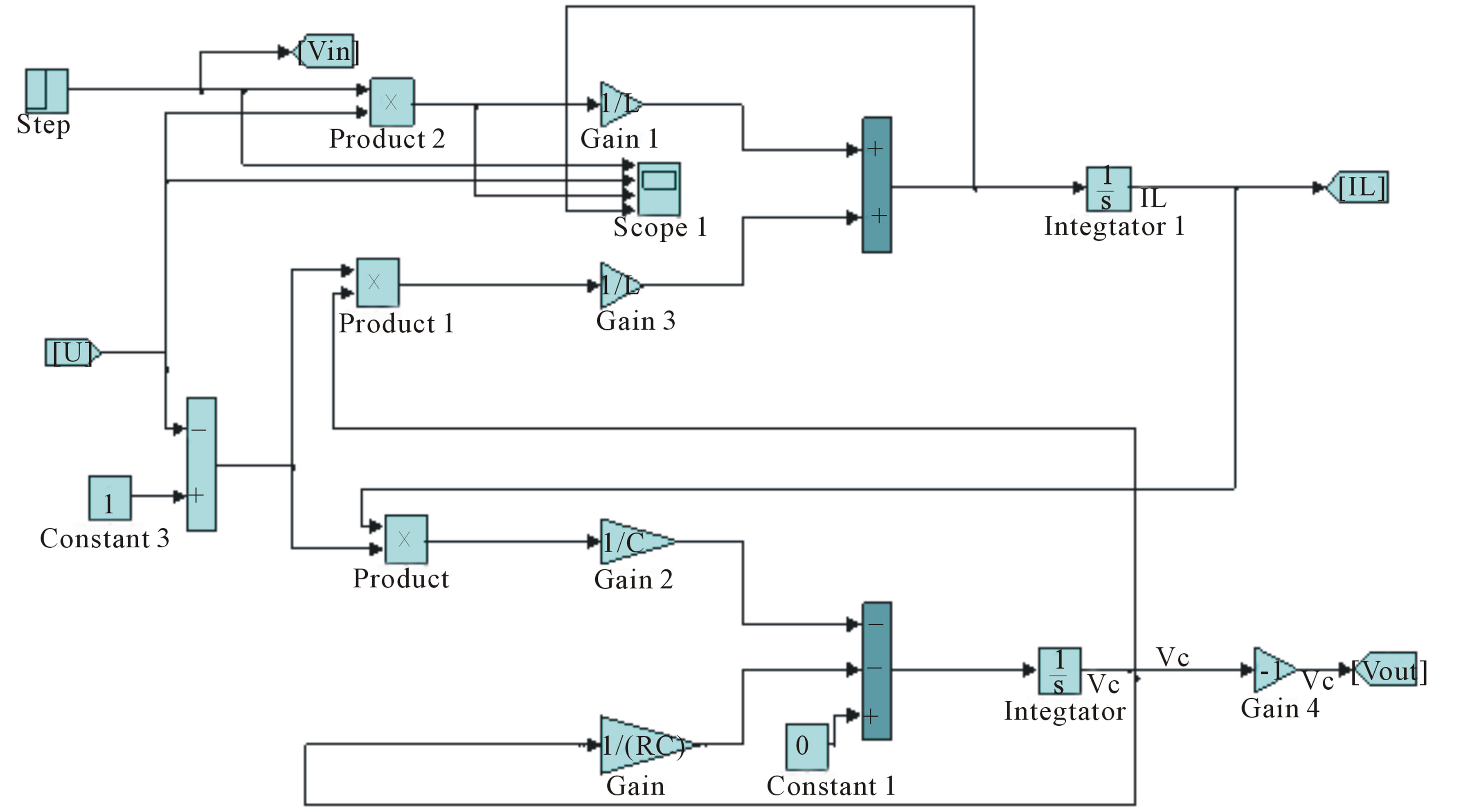
Figure 4. Simulink model of a single buck boost converter.
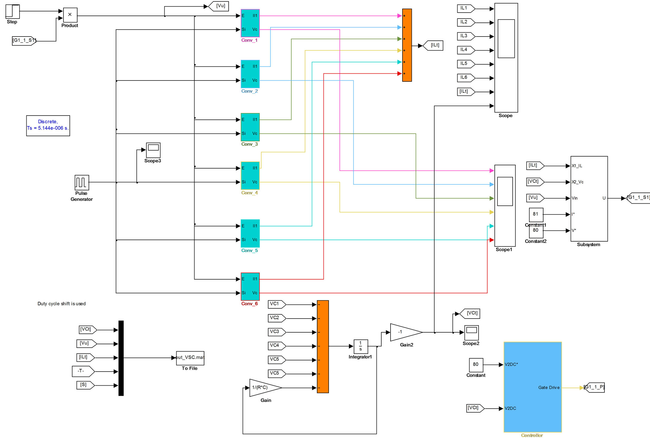
Figure 5. Simulink model of six paralleled buck boost converters.
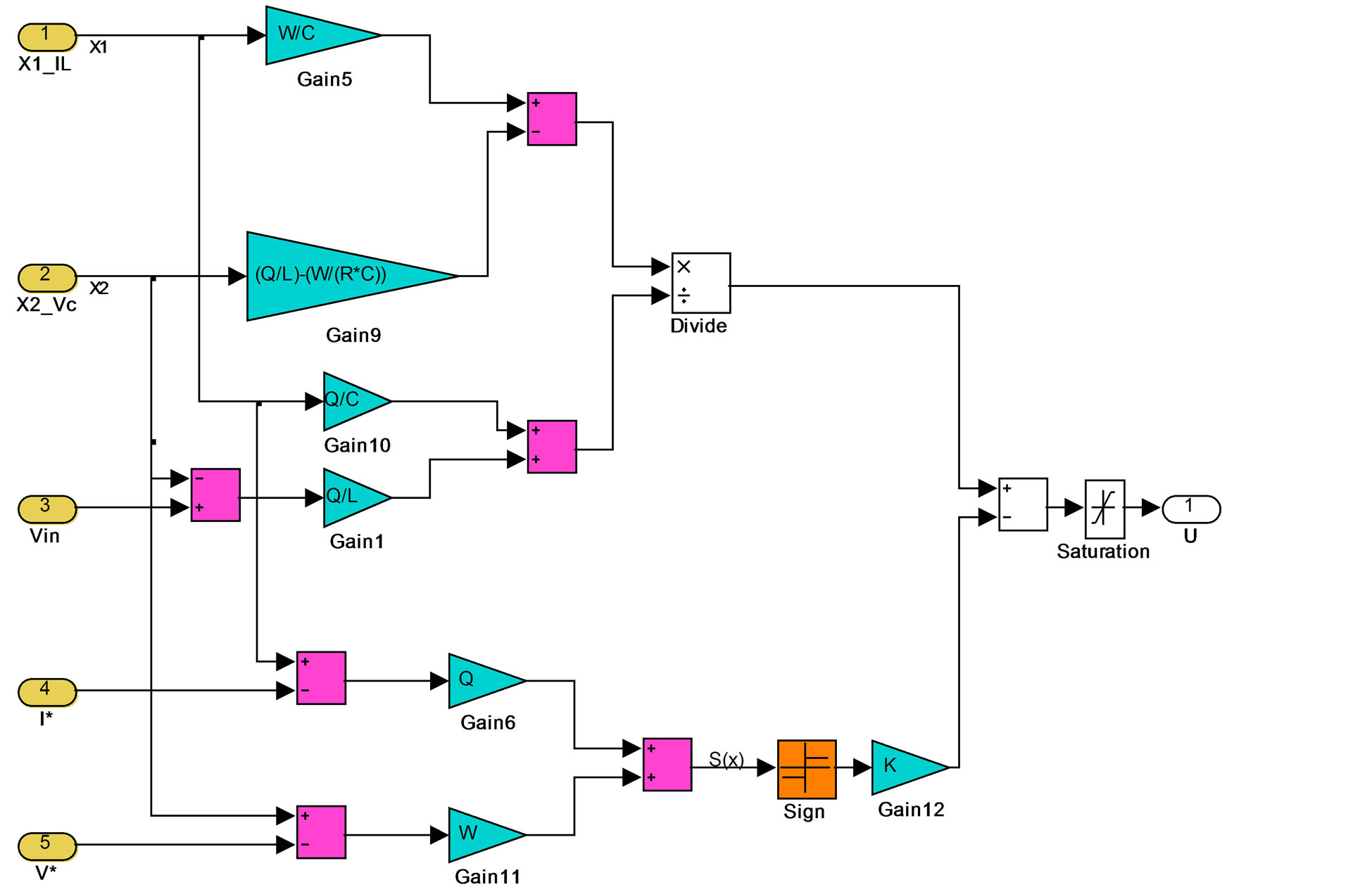
Figure 6. Simulink model of the control circuit as given in Equation (24).
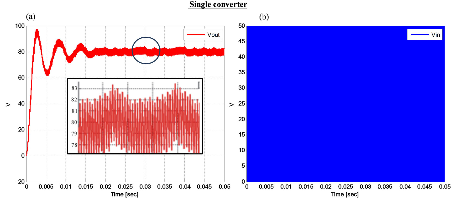
Figure 7. Output voltage, switched input voltage and a close-up of the output voltage of a single buck boost converter.
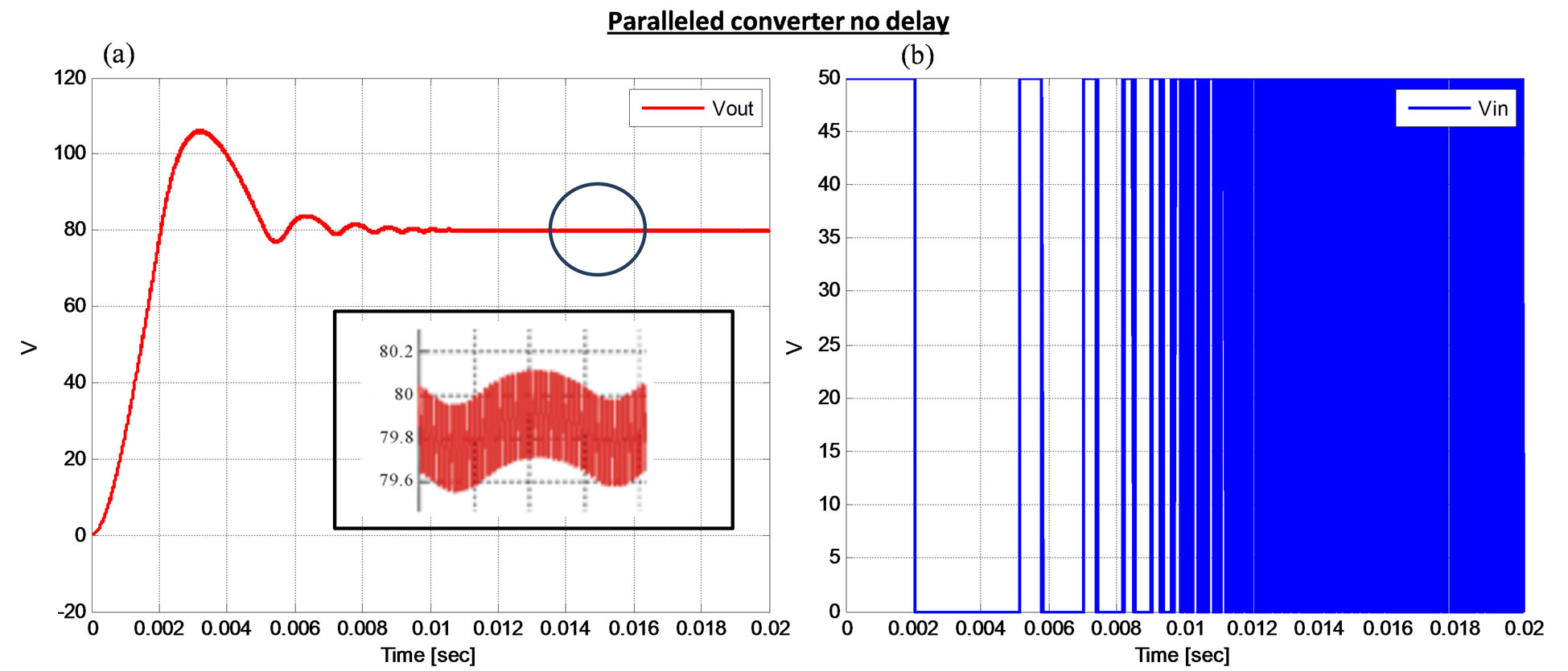
Figure 8. Output voltage, switched input respectively for paralleled converters with constant duty cycle at the performance mode.
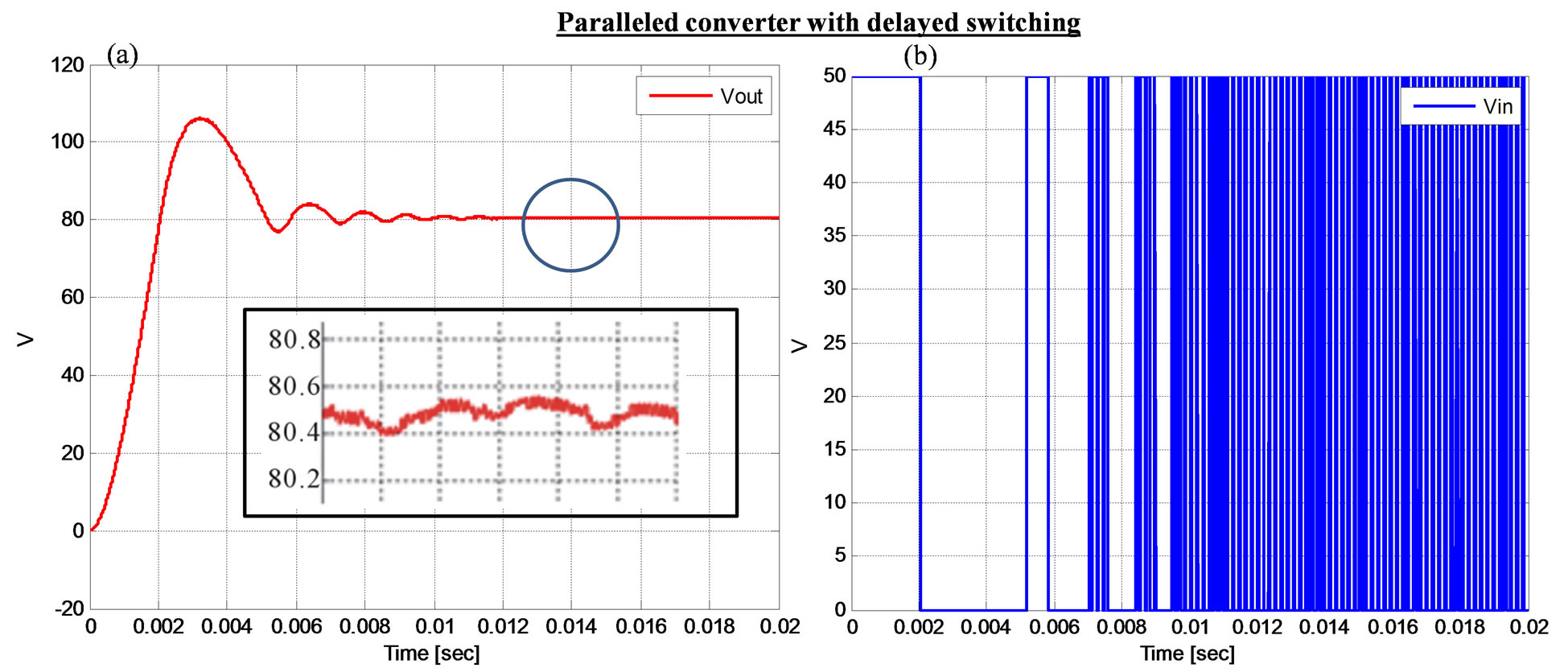
Figure 9. Output voltage, switched input voltage respectively for paralleled converters with enhanced duty cycle at the performance mode.
delayed switching time in the performance stage as suggested by Equation (12) has shown a great deal of improvement. Examining the switched input voltages, it can be seen that the proposed two stage converter has reduced the switching frequency hence reducing the switching losses of the converter in the input stage. The performance stage switching frequency and duty cycle can be optimized to improve the overall efficiency of the system.
Figure 10 shows further improvement on the overall performance of the converters by reducing the ripple and improving the system response to eliminate any overshoot or oscillations. Figures 11(a) and (b) show he best performance with elimination of ripples and reduction in harmonics content, better system response as the desired voltage is being reached without the overshoot or oscillations.
6. Conclusions
This paper develops a paralleled Buck Boost DC-DC converter with two stages named the control and the performance stages. The control stage performed a manipulation of the input voltage whereas the performance stage was designed to improve further the quality of the output. The quality is measured by reducing the ripples, hence reducing power lost and increasing system reliability.
The converter is controlled using Sliding Mode Control method. The sliding surface in the controlled is developed to be dynamic and duty cycle dependent. This dynamic hyper plane or sliding surface showed an expected improved performance. The results also showed an improved overall performance over typical PID controller, and there was no overshoot or settling time, tracking the desired output nicely. The enhanced mode in combination
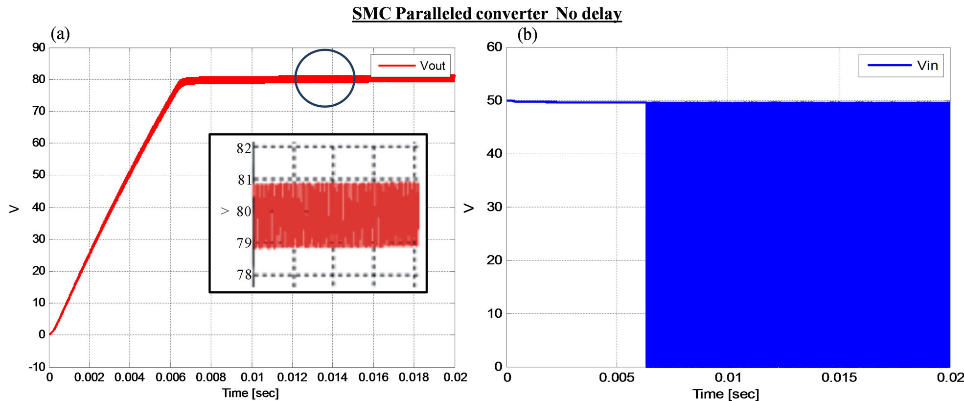
Figure 10. Output voltage, switched input voltage respectively for paralleled converters with constant duty cycle at the performance mode using SMC.
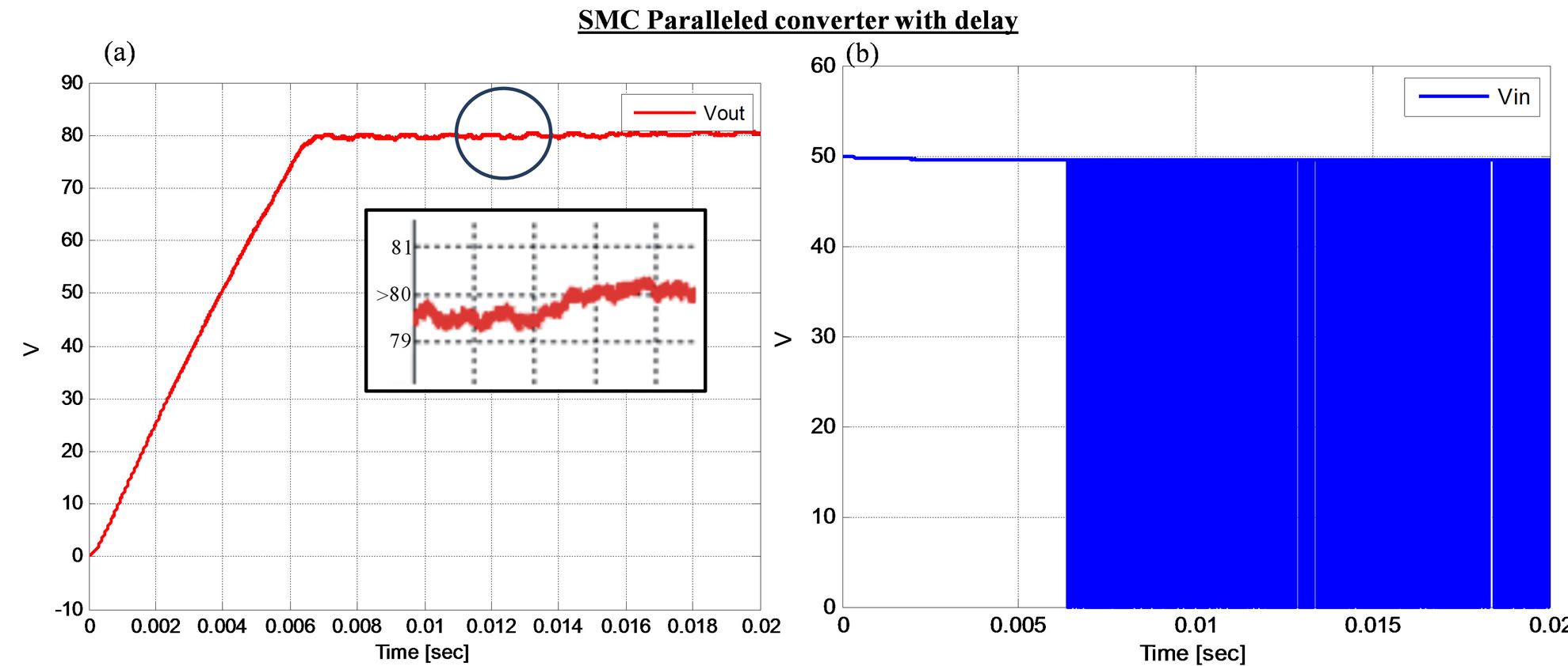
Figure 11. Output voltage, switched input voltage respectively for paralleled converters with enhanced duty cycle at the performance mode using SMC.
with the sliding mode control has shown a reduction in harmonics in comparison to the SMC without the delayed enhanced mode.
With the increasing demand of large power load and the development of distributed power supply system, the importance of research on paralleled power supply modules is increasing, while achieving an equivalent current sharing between the modules is the key element. In future work, the current-sharing control will be presented and compared with other existing ones.
REFERENCES
- B. Khasawneh, M. Sabra and M. Zohdy, “Novel Operating Mode for DC-to-DC Converters in PHEVs,” SAE Technical Paper 2013-01-1761, 2013.
- S. K. Mazumder, A. H. Nayfeh and A. Borojevic, “Robust Control of Parallel DC-DC Buck Converters by Combining Integral-Variable-Structure and Multiple-Sliding-Surface Control Schemes,” IEEE Transactions on Power Electronics, Vol. 17, No. 3, 2002, pp. 428-437. http://dx.doi.org/10.1109/TPEL.2002.1004251
- T. Kohama, T. Ninomiya, M. Shoyama and F. Ihara, “Dynamic Analysis of Parallel-Module Converter System with Current Balance Controllers,” 16th International Telecommunications Energy Conference, INTELEC’94, 1994, pp. 190-195.
- V. J. Thottuvelil and G. C. Verghese, “Analysis and Control Design of Paralleled DC/DC Converters with Current Sharing,” IEEE Transactions on Power Electronics, Vol. 13, No. 4, 1998, pp. 635-644. http://dx.doi.org/10.1109/63.704129
- K. Siri, C. Q. Lee and T. Wu, “Current Distribution Control for Parallel Connected Converters. I,” IEEE Transactions on Aerospace and Electronic Systems, Vol. 28, No. 3, 1992, pp. 829-840. http://dx.doi.org/10.1109/7.256303
- Qing Chen, “Stability Analysis of Paralleled Rectifier Systems,” 17th International Telecommunications Energy Conference, INTELEC’95, 1995, pp. 35-40.
- J. Rajagopalan, K. Xing, Y. Guo, F. C. Lee and B. Manners, “Modeling and Dynamic Analysis of Paralleled DC/ DC Converters with Master-Slave Current Sharing Control,” 11th Annual Conference Proceedings on Applied Power Electronics Conference and Exposition, APEC’96, Vol. 2, 1996, pp. 678-684.
- Y. Panov, J. Rajagopalan and F. C. Lee, “Analysis and Design of N Paralleled DC-DC Converters with MasterSlave Current-Sharing Control,” 12th Annual Conference Proceedings on Applied Power Electronics Conference and Exposition, APEC’97, Vol. 1, 1997, pp. 436-442.
- D. S. Garabandic and T. B. Petrovic, “Modeling Parallel Operating PWM DC/DC Power Supplies,” IEEE Transactions on Industrial Electronics, Vol. 42, No. 5, 1995, pp. 545-551. http://dx.doi.org/10.1109/41.464619
- P. V. Kokotovic, “The Joy of Feedback: Nonlinear and Adaptive,” IEEE Control Systems, Vol. 12, No. 3, 1992, pp. 7-17. http://dx.doi.org/10.1109/37.165507
- Krstic, Miroslav, I. Kanellakopoulos and P. V. Kokotovic, “Nonlinear and Adaptive Control Design,” John Wiley & Sons, New York, 1995.
- Khalil and K. Hassan, “Nonlinear Systems,” Prentice Hall, Upper Saddle River, 2002.
- Slotine, E. Jean-Jacques and W. P. Li, “Applied Nonlinear Control,” Vol. 199, No. 1, Prentice Hall, Upper Saddle River, 1991.
- M. Zohdy, M. S. Fadali and J. Liu, “Variable Structure Control Using System Decomposition,” IEEE Transactions on Automatic Control, Vol. 37, No. 10, 1992, pp. 1514-1517. http://dx.doi.org/10.1109/9.256371
- M. A. Zohdy, M. S. Fadali and J. Liu, “Variable Structure Dynamic Output Feedback,” Proceedings of the 1995 American Control Conference, Vol. 2, 1995, pp. 1518- 1522. http://dx.doi.org/10.1109/ACC.1995.521005
- Utkin and I. Vadim, “Sliding Modes in Control and Optimization,” Vol. 116, Springer-Verlag, Berlin, 1992.
- Sastry and Shankar, “Nonlinear Systems: Analysis, Stability, and Control,” Vol. 10, Springer, New York, 1999.
- Jamshidi, Mohammad, et al., “Applications of Fuzzy Logic: Towards High Machine Intelligence Quotient Systems,” Prentice-Hall Inc., Upper Saddle River, 1997.
- I. Batarseh, K. Siri and H. Lee, “Investigation of the Output Droop Characteristics of Parallel-Connnected DC-DC Converters,” 25th Annual IEEE Power Electronics Specialists Conference, PESC’94 Record., Vol. 2, 1994, pp. 1342-1351.
- J. J. Shi, L. B. Zhou and X. N. He, “Common-Duty-Ratio Control of Input-Parallel Output-Parallel (IPOP) Connected DC-DC Converter Modules with Automatic Sharing of Currents,” IEEE Transactions on Power Electronics, Vol. 27, No. 7, 2012, pp. 3277-3291. http://dx.doi.org/10.1109/TPEL.2011.2180541
- Batarseh, K. Siri and H. Lee, “Investigation of the Output Droop Characteristics of Parallel-Connnected DC-DC Converters,” 25th Annual IEEE Power Electronics Specialists Conference, PESC’94 Recordings, 1994, Vol. 2, pp. 1342- 1351.
- A. G. Beccuti, M. Kvasnica, G. Papafotiou and M. Morari, “A Decentralized Explicit Predictive Control Paradigm for Parallelized DC-DC Circuits,” IEEE Transactions on Control Systems Technology, Vol. 21, No. 1, 2013, pp. 136-148. http://dx.doi.org/10.1109/TCST.2011.2178071
- A. A. Aboushady, K. H. Ahmed, S. J. Finney and B. W. Williams, “Linearized Large Signal Modeling, Analysis, and Control Design of Phase-Controlled Series-Parallel Resonant Converters Using State Feedback,” IEEE Transactions on Power Electronics, Vol. 28, No. 8, 2013, pp. 3896-3911. http://dx.doi.org/10.1109/TPEL.2012.2231700
- W. Qian, H. Y. Cha, F.-Z. Peng and L. M. Tolbert, “55-kW Variable 3X DC-DC Converter for Plug-In Hybrid Electric Vehicles,” IEEE Transactions on Power Electronics, Vol. 27, No. 4, 2012, pp. 1668-1678. http://dx.doi.org/10.1109/TPEL.2011.2165559
- Jamerson, Cliff and C. Mullett, “Paralleling Supplies via Various Droop Methods,” High-Frequency Power Conversion Conference (HFPC) Proceedings, 1994, pp. 68- 76.
- M. Grossoni and G. Cimador, “A Selective Supervision Device for Paralleling Operating ac/dc and dc/dc Converters,” 5th International Telecommunications Energy Conference, INTELEC’83, 1983, pp. 587-593.
- R.-H. Wu, T. Kohama, Y. Kodera, T. Ninomiya and F. Ihara, “Load-Current-Sharing Control for Parallel Operation of DC-to-DC Converters,” 24th Annual IEEE Power Electronics Specialists Conference, PESC’93 Recordings, 1993, pp. 101-107.
- Y. Panov, J. Rajagopalan and F. C. Lee, “Design-Oriented Analysis of Paralleled dc-dc Converters with Master-Slave Current-Sharing Control,” Proceedings of the Annual Seminar of Virginia Power Electronics Seminar, 1996, pp. 83-89.
- V. I. Utkin, J. Guldner and J. Shi, “Sliding Mode Control in Electromechanical Systems (Vol. 9),” CRC Press, Boca Raton, 1999.
- Freeman, A. Randy and P. V. Kokotovic, “Robust Nonlinear Control Design: State-Space and Lyapunov Techniques,” Springer, Berlin, 2008.
- Z. H. Qu, “Robust Control of Nonlinear Uncertain Systems,” John Wiley & Sons, Inc., Hoboken, 1998.
- M. M. Gupta and T. Yamakawa, “Fuzzy Computing: Theory, Hardware, and Applications,” North-Holland, 1988.
- Kandel, Abraham, and G. Langholz, “Fuzzy Control Systems,” CRC Press, Boca Raton, 1994.
- E. Fossas and G. Olivar, “Study of Chaos in the Buck Converter,” IEEE Transactions on Circuits and Systems I: Fundamental Theory and Applications, Vol. 43, No. 1, 1996, pp. 13-25.
- M. Grossoni and G. Cimador, “A Selective Supervision Device for Paralleling Operating AC/DC and DC/DC Converters,” 5th International Telecommunications Energy Conference, INTELEC’83. 1983, pp. 587-593.
- S. Gutman, “Uncertain Dynamical Systems—A Lyapunov Min-Max Approach,” IEEE Transactions on Automatic Control, Vol. 24, No. 3, 1979, pp. 437-443. http://dx.doi.org/10.1109/TAC.1979.1102073
- D. C. Hamill, J. H. B. Deane and D. J. Jefferies, “Modeling of Chaotic DC-DC Converters by Iterated Nonlinear Mappings,” IEEE Transactions on Power Electronics, Vol. 7, No. 1, 1992, pp. 25-36. http://dx.doi.org/10.1109/63.124574
- S. K. Mazumder, A. H. Nayfeh and D. Boroyevich, “Theoretical and Experimental Investigation of the Fastand Slow-Scale Instabilities of a DC-DC Converter,” IEEE Transactions on Power Electronics, Vol. 16, No. 2, 2001, pp. 201-216. http://dx.doi.org/10.1109/63.911144
- C. K. Tse, “Flip Bifurcation and Chaos in Three-State Boost Switching Regulators,” IEEE Transactions on Circuits and Systems I: Fundamental Theory and Applications, Vol. 41, No. 1, 1994, pp. 16-23.
- J. R. Wood, “Chaos: A Real Phenomenon in Power Electronics,” Proceedings of 4th Annual IEEE on Applied Power Electronics Conference and Exposition, Baltimore, 13-17 March 1989, pp. 115-124. http://dx.doi.org/10.1109/APEC.1989.36959
- R.-H. Wu, T. Kohama, Y. Kodera, T. Ninomiya and F. Ihara, “Load-Current-Sharing Control for Parallel Operation of DC-to-DC Converters,” 24th Annual IEEE Power Electronics Specialists Conference, Seattle, 20-24 June 1993, pp. 101-107.
- B. Tomescu and H. F. VanLandingham, “Improved LargeSignal Performance of Paralleled DC-DC Converters Current Sharing,” IEEE Transactions on Power Electronics, Vol. 14, No. 3, 1999, pp. 573-577. http://dx.doi.org/10.1109/63.761701
- R. Marino and P. Tomei, “Nonlinear Control Design: Geometric, Adaptive and Robust,” Prentice Hall International (UK) Ltd., 1996.
- B. Khasawneh, M. Sabra and M. Zohdy, “Power Converters Variable Structure Control Surface Design,” 3rd International Conference on Electric Power and Energy Conversion Systems (EPECS’13), August 2013, Article ID: 167-55397.