Journal of Materials Science and Chemical Engineering
Vol.06 No.12(2018), Article ID:89321,15 pages
10.4236/msce.2018.612001
Fabrication of Solvent-Resistant Nanofiltration Membrane via Interfacial Polymerization Based on Cellulose Acetate Membrane
Chen Su1, Lina Chi1*, Yingjia Qian1, Siwei Sun1, Zheng Jiang2
1School of Environmental Science and Engineering, Shanghai Jiao Tong University, Shanghai, China
2Faculty of Engineering and the Environment, University of Southampton, Southampton, UK

Copyright © 2018 by authors and Scientific Research Publishing Inc.
This work is licensed under the Creative Commons Attribution International License (CC BY 4.0).
http://creativecommons.org/licenses/by/4.0/


Received: May 30, 2018; Accepted: December 18, 2018; Published: December 21, 2018
ABSTRACT
Although a great progress has been achieved for the development of NF membranes and technologies and SRNF do show a great potential in the separation of organic components, an NF membrane with good separation performance and good resistance to organic solvents are urgently needed for a more complicated situation in practical. In this study, a kind of solvent-resistant nanofiltration (SRNF) membrane was fabricated via interfacial polymerization on a laboratory optimized cellulose acetate (CA) basic membrane. The effects of interfacial polymerization parameters, such as water phase concentration, immersed time in the water phase and in the organic phase, on the pure water flux and rejection rate of C-2R yellow dyestuffs were investigated. A highest dye rejection rate of 72.9% could be obtained by water phase solution containing 1% m-xylylenediamine (mXDA) and organic phase solution with 0.2% trimesoyl chloride (TMC) under immersed time in water phase of 6 minutes and in organic phase of 40 seconds. This membrane demonstrated better resistance to methyl alcohol compared to commercial membrane. This study may offer an avenue to develop a solvent-resistant nanofiltration membrane.
Keywords:
Cellulose Acetate, Interfacial Polymerization, Solvent-Resistant Nanofiltration Membrane

1. Introduction
Membrane technology as an efficient and environmental friendly approach to purify wastewater is becoming increasingly important in facing the current global water crisis. Traditional membrane processes are driven by the transmembrane pressure, which generally include microfiltration (MF), ultrafiltration (UF), nanofiltration (NF) and reverse osmosis (RO). NF membrane with a molecular weight cut-off of 350 - 1000 Da [1] is regarded as a separation process between UF and RO. Due to the repulsive effect and the steric hindrance effect, NF membranes are able to effectively reject multi-valent salts and some organic molecules with small sizes [2] . With the fast development of NF membranes, the need for NF membranes is also growing rapidly. There is a huge demand for NF membranes with excellent performance in some industries or processes like wastewater treatment [3] , food processing [4] , desalination [5] and removal of heavy metals [6] .
In the past several decades, great efforts have also been taken to develop polymeric NF membranes with different kinds of materials including inorganic and polymeric materials. Compared to inorganic materials, the polymeric materials are flexible and prone to form membranes. As a result, the commercial NF membranes are mainly prepared with organic materials like polyamides (PA) [7] , cellulose acetate (CA) [8] , polyether sulfone (PES) [9] , polyimide (PI) [10] and polyvinyl alcohol (PVA) [11] , which is fabricated by phase inversion method.
In addition, the invention of thin-film composites (TFC) revolutionizes the traditional awareness towards NF membranes. Different from phase inversion method, TFC membranes are composed of a selective layer on a porous support. Constructing a separation layer by interfacial polymerization (IP) on the support layer of UF membrane can significantly improve the properties of NF membrane. IP is a quite common technique to construct the selective layer of TFC membranes [12] . In a typical process, a polymeric UF membrane is first soaked in an aqueous solution of amine monomers like m-phenylamine (MPD), triethanolamine (TEOA), piperazine. Subsequently, the membrane will be dipped in an organic solution containing the crosslinker, trimesoyl chloride (TMC) [13] [14] . The two phases may quickly react to yield the PA selective layer on the porous support.
In recent years, solvent-resistant nanofiltration (SRNF) has been an emerging technology. Organic matters with molecular weights between 200 and 2000 g・mol-1 can be separated by a SRNF membrane [15] . In this way, membrane could have more efficient separation processes in organic solvents and the energy cost of the operation can be saved compared to some traditional processes like distillation. Therefore, the potential of SRNF now has made itself to be applied in catalysis [16] [17] [18] , food processing [19] [20] , chemistry industry [21] [22] and the membrane bioreactors (MBR) [23] .
Although a great progress has been achieved for the development of NF membranes and technologies and SRNF do show a great potential in the separation of organic components, a NF membrane with good separation performance and good resistance to organic solvents are urgently needed for a more complicated situation in practical.
In this study, SRNF membranes were fabricated based on a lab-made cellulose acetate membrane via interfacial polymerization with different fabrication parameters. The fabricated SRNF membranes were characterized by scanning electron microscope (SEM), Fourier transform infrared spectra (FTIR) and X-ray diffractometer (XRD). The objective of this study was to investigate the effect of fabrication parameters (water phase concentration, immersed time in the water phase and organic phase) on morphology and crystallinity of the fabricated SRNF membranes. The lab made SRNF membranes were further immersed in methyl alcohol to test their resistance to organic solvent.
2. Experimental
2.1. Materials and Reagents
Cellulose acetate (CA), bovine serum albumin (BSA), sodium dodecyl benzene sulfonate (SDBS), polyethylene glycol (PEG M.W. = 600, 1000, 2000, 4000), triethylamine, Polyvinyl Pyrrolidone (PVP), lithium chloride (LiCl) and 98% hydrochloric acid (HCl) were all purchased from Sinopharm Chemical Reagent Co. Ltd. (Shanghai, China). Dimethyl sulfoxide (DMSO), N,N-dimethylformamide (DMF) and n-hexane were supplied by Lingfeng Chemical Reagent Co. Ltd. (Shanghai, China). mXDA and TMC are provided by Sigma-Aldrich (America).
2.2. Preparation of the Basic Cellulose Acetate Membranes
CA membranes were fabricated by non-solvent induced phase separation (NIPS) method [24] . In order to optimize the constituents of CA membrane, 12 different types of membranes were prapared. The recipes of all the membranes are shown in Table 1.
The phase inversion process was used to prepare the membranes. In detail, the casting solution was prepared by adding polymer CA and additives in DMAc or DMSO or their mixture. The prepared solution was mechanically stirred at 70˚C for 6 hours. After thorough mixing, the casting solution was left for 24 h for degassing (at the same temperature without stirring). The casting solution was casted at a speed of 1.2 - 1.4 m/min on a glass plate at temperature of 60˚C. The polymer films were shortly (10 s) exposed to ambient air and then immersed in a DI water coagulation bath at room temperature. After complete coagulation, the membrane was transferred and kept in ultrapure water for overnight to attain complete removal of solvent from the membrane.
2.3. Preparation of the Solvent-Resistant NF Membranes
The SRNF membranes were prepared via interfacial polymerization. The specific procedures are described as follows.
The fabricated CA membrane was first immersed in the mXDA aqueous solution. The concentration of mXDA ranged from 1 to 4 wt% and the immersed

Table 1. The ratio of different constituents of casting solution for twelve CA membranes.
time varied from 3 to 15 minutes. Then the immersed membrane was taken out from the water phase and the extra water on the surface of the membrane was air dried at room temperature. The membrane was subsequently immersed in the 0.2% TMC solution to form a polyamide layer by interfacial polymerization. The immersed time varied from 10 to 180 seconds. Finally, the membrane was put into an oven at 80˚C for 30 minutes for further polymerization in order to form a dense and thin surface. The resultant membrane was stored in deionized water before it was tested. The reaction formula has been shown in Figure 1.
2.4. Characterization
The surface and cross-sectional morphology of prepared membranes were observed by scanning electron microscopy (SEM, Sirion 200, FEI).
The chemical structure and composition of the surface of membranes were analyzed by Fourier transform infrared spectra (FTIR, Thermo Fisher, Nicolet 6700). The samples were dried before characterization.
The degrees of crystallinity of membranes were indicated by X-ray diffractometer (D/MAX-313, Japan). The scanning angle ranged from 5˚ to 70˚ and the scanning speed was about 3˚/min.
The porosity of the membrane can be determined by using Equation (1)
(1)
where Ww is the wet weight of the membrane, Wd is the dry weight of the membrane, Am is the total membrane area, L is the thickness of the membrane and is the density of water.
2.5. Performance Evaluations
Separation performance of the membranes was measured in a dead-end stirred
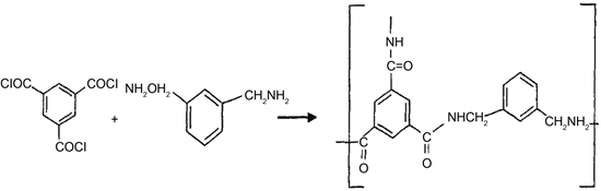
Figure 1. Reaction formula of the preparation of polyamid.
cell. A filtration cell (effective area 34.9 cm2 for CA basic membranes and 13.9 cm2 for SRNF membranes) was connected with a nitrogen cylinder and a solution reservoir. The stirred cell and reservoir were initially filled with DI water. The membranes were first compacted by DI water at 0.1 MPa for 30 minutes. Then the pure water flux was measured at 0.1 Mpa (for CA basic membranes) or 0.35 Mpa (NF membranes) by determining the filtrate mass using an electronic balance. The stirred cell and reservoir were then emptied and refilled with a desired solution (100 mg/L BSA or 50 mg/L dye solution) to evaluate the rejection rate of the membrane. 3 repetitions have been done for each group during the measurement. All filtration experiments were conducted at room temperature (20˚C ± 2˚C).
The water permeate flux (Jw) and solute rejection (R) were calculated by Equations (2) and (3):
(2)
(3)
where V (L) was the volume of permeated water, A (m2) was the membrane area and Δt (h) was the permeation time. Cp (g/L) and Cf (g/L) were the concentrations of permeate and feed solutions, respectively.
Concentrations of BSA and C-2R yellow aqueous solutions were measured with an ultraviolet visible spectrophotometer (Cary 60, Agilent Technologies) at 280 nm and 416 nm respectively.
3. Results and Discussion
3.1. The Performance of Lab Made CA Membranes
Table 2 provides the details of the performance (including viscosity, porosity, pure water flux and rejection rate of BSA) of twelve lab made CA membranes. Membrane 4, containing 15% acetic acid fiber, 400 ml DMF and 1% PEG4000, was selected as the basic membrane for further interfacial polymerization, as it resulted in the high selectivity of BSA, appropriate porosity and an acceptable pure water flux.
Table 2. The performance of twelve CA membranes.
3.2. Optimization of Interfacial Polymerization Reaction
3.2.1. The Effect of Aqueous Phase Concentration
Figure 2 shows the effect of mXDA concentration on the water flux and dye rejection. When the mXDA concentration increased from 1 to 4 wt%, water flux first increased from 4.74 to 5.38 LMH, then decreased from 5.38 to 4.85 LMH and finally increased again from 4.85 to 6.1 LMH. The rejection rate of C-2R yellow gradually decreased from 59.0% to 33.1%.
Figure 3 shows the FTIR spectra of NF membranes formed by different mXDA concentration. As shown in Figure 3, membranes with lower water phase concentration may have stronger absorption peak intensity at the characteristic wavelength. During the process of interfacial polymerization, due to the low concentration of mXDA, the diffusion speed and capacity will become slower and less. This will cause excess amounts of TMC remained in reaction medium which brought more liner amide unit with acid pedant group and therefore the ratio of 1740/1640 increased. As a result, the performance of NF membrane gets worse with the increase of water phase concentration.
Table 3 presents the degree of crystallinity of NF membranes with different water phase concentration. It can be concluded that the water phase concentration does little impact on the degree of crystallinity.
According to the results shown above, in order to get a high rejection rate of dyes and a large pure water flux, the mXDA concentration was fixed at 2% in the following experiments.
3.2.2. The Effect of Aqueous Phase Immersing Time
Figure 4 shows the effect of immersed time in water phase on the water flux and dye rejection. From Figure 4, when immersed time in mXDA increased from 3 minutes to 15 minutes, the pure water flux decreases first and increases with the increase of immersed time. On the contrary, the rejection rate of C-2R yellow
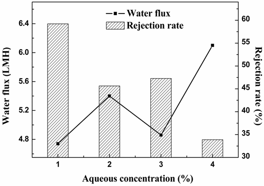
Figure 2. Effect of mXDA concentration on membrane performance.

Figure 3. FTIR spectra of NF membranes formed by different mXDA concentration: (a) 1% mXDA; (b) 2% mXDA; (c) 4% mXDA.
increases first and decreases subsequently. Since CA membrane is hydrophilic, when dipping the CA membrane in mXDA, it is easy to form a layer of water on the membrane surface in a quite short time. Therefore, increasing the immersed time in water phase may have little impact on the membrane properties.
Figure 5 is the FTIR spectra of NF membranes formed by different immersed time in mXDA. The absorption strengths of characteristic peak at 1740/1640 of 180 s and 360 s were stronger. With the increase of reaction time in water phase, the strength at this value was becoming weaker. Besides, results of degree of crystallinity at 6 minutes in Table 4 are the highest. Therefore, the immersed
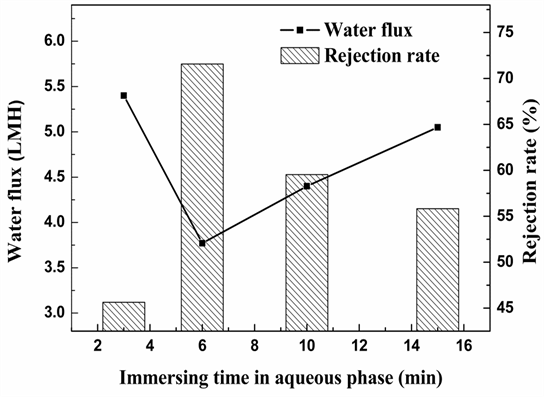
Figure 4. Effect of immersed time in water phase on membrane performance.
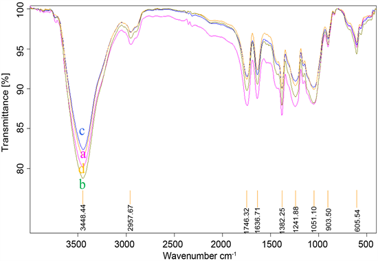
Figure 5. FTIR spectra of NF membranes formed by different immersed time in mXDA: (a) 180 s; (b) 360 s; (c) 600 s; (d) 900 s.
Table 3. The degree of crystallinity of NF membranes with different concentrations in water phase.
time water phase was set at 6 min in the following experiments.
3.2.3. The Effect of the Organic Phase Immersing Time
Figure 6 shows the effect of immersed time in organic phase on the water flux and dye rejection. From Figure 6, when immersed time in TMC increased from 10 s to 180 s, the pure water flux reaches its maximum at 120 s. On the contrary, the rejection rate of C-2R yellow increases first and decreases subsequently. This phenomenon implies that when the immersed time in the organic phase was less than 40 s, the polyamide layer may constantly improve with the reaction time increases. Therefore, the flux decreases and rejection rate increases before 40 s. While the immersed time in the organic phase was more than 120 s, the formed functional layer started to become the barrier between the two reaction phases and it prevented the monomer from diffusing to the interface. As a result, the pure water flux and rejection rate maintained constant after 120 s. In view of the rejection rate, the optimal condition in the organic phase is set to 40 s. Figure 7 shows the FTIR spectra of NF membranes formed by different immersed time in TMC. The absorption strengths of characteristic peak at 1740/1640 of 10 s and 60 s were stronger. With the increase of reaction time in TMC, the strength at this value was becoming weaker except the one immersing in TMC for 60 s. However, taken the degree of crystallinity as shown in Table 5, 40 s could be the best choice since highest degree of crystallinity means the highest tensile strength. The tightly stacked molecular chains in the crystals can better prevent the penetration of various kinds of reagents and improve the solvent resistance and rejection of membranes.
3.3. Study of the Optimal Polyamide NF Membrane
3.3.1. FT-IR Analysis
After preparing the polyamide NF membrane under the selected optimal treat-
Table 4. The degree of crystallinity of NF membranes with different immersed time in water phase.
Table 5. The degree of crystallinity of NF membranes with different immersed time in organic phase.
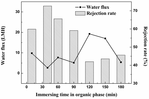
Figure 6. Effect of immersed time in organic phase on membrane performance.

Figure 7. FTIR spectra of NF membranes formed by different immersed time in TMC: (a) 10 s; (b) 40 s; (c) 60 s; (d) 120 s.
ing condition, the obtained NF membrane was analyzed by the FT-IR spectrum. Figure 8 compares the FT-IR spectrum of polyamide NF membrane to that of the CA substrate. The spectrum of the NF membrane clearly shows characteristic absorption peaks at 1670 and 1525 cm−1 correspond to C=O of amide Istretching and NH of amide II vibrations, which indicates the formation of the functional polyamide layer on the CA substrate surface [10] .
3.3.2. Morphology Changes in Methanol
The polyamide nanofiltration membrane was prepared by the optimal condition first. In order to test the endurance of this fabricated NF membrane towards
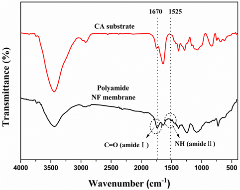
Figure 8. The FT-IR spectra of CA substrate and polyamide NF membrane.
organic solvent, the farbricated membrane was immersed in methanol for one day and then its performance and surface morphology were tested.
Figure 9 is the morphology of the fabricated CA substrate and SRNF membranes before and after immersed in methanol. From Figure 9(a) and Figure 9(b), the pore size of the lab made CA membranes ranged from 0.05 μm to 0.1 μm, which implies that the fabricated CA membrane was ultrafiltration membrane. From Figure 9, the pore size of the SRNF membranes ranged from 1 to 51 nm, which implies that the fabricated membrane was nanofiltration membrane. After dipped into methanol for 1 day, CA membrane didn’t show obvious swelling on its surface but the pore size of the dipped membrane also decreased a little.
3.3.3. Performance of the Optimal Polyamide NF Membrane
From above, the optimal conditions for the SRNF membranes were confirmed.
Three different types of membranes, lab optimized CA membrane, commercial CA membrane and CA membrane with support layer, were compared for their resistance to organic solvent. The results are shown in Figure 10 and Table 6.
Figure 10 shows the picture of different CA membranes after immersed in methanol for 1 day. It is obvious that the commercial membrane has swelling on its surface after immersed in methanol while the lab made one didn’t show obvious change.
Table 6 shows the performance change of several membranes before and after immersed in methanol. It can be concluded that membranes with support layer may have great performance degradation after immersion in methanol. Although the optimized CA might also have performance degradation after immersion in methanol, the related SRNF was quite stable towards organic solvent. The lab
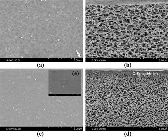
Figure 9. The SEM images of CA substrate surface (a), cross section (b), and polyamide NF membrane surface (c), cross section (d), NF membrane surface after being immersed in methanol for 24 h (e).
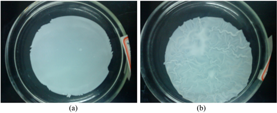
Figure 10. Picture of CA membranes after immersed in methanol for 1 day: (a) Lab made membrane, (b) Commercial membrane.
Table 6. The performance of membranes before and after immersed in methanol.
made SRNF can have a rejection rate of 71.09% towards C-2R yellow.
4. Conclusion
A kind of solvent-resistant nanofiltration (SRNF) membrane was fabricated via interfacial polymerization on a laboratory optimized cellulose acetate basic membrane. The laboratory optimized cellulose acetate basic membrane was obtained by homogeneous experiment and it has a rejection rate of 39.97% towards 100 mg/L BSA. Using the CA membrane as the basic membrane, the optimized SRNF showed a C-2R yellow rejection of 72.9% and had a better resistance to methyl alcohol compared to commercial membrane. This study may offer a feasible way to develop a solvent-resistant nanofiltration membrane.
Acknowledgements
We acknowledge the financial support by National Key Project on Prevention and Control of Water Pollution from Ministry of Environmental Protection of China (2017ZX07203-005), NSFC Major Project (21737002) and the Newton Research Collaboration Award from Royal Academy of Engineering, UK (Reference: NRCP/1415/261).
Conflicts of Interest
The authors declare no conflicts of interest regarding the publication of this paper.
Cite this paper
Su, C., Chi, L.N., Qian, Y.J., Sun, S.W. and Jiang, Z. (2018) Fabrication of Solvent-Resistant Nanofiltration Membrane via Interfacial Polymerization Based on Cellulose Acetate Membrane. Journal of Materials Science and Chemical Engineering, 6, 1-15. https://doi.org/10.4236/msce.2018.612001
References
- 1. Tul Muntha, S., Kausar, A. and Siddiq, M. (2016) Advances in Polymeric Nanofiltration Membrane: A Review. Polymer-Plastics Technology and Engineering, 56, 841-856. https://doi.org/10.1080/03602559.2016.1233562
- 2. Mohammad, A.W., Teow, Y.H., Ang, W.L., Chung, Y.T., Oatley-Radcliffe, D.L. and Hilal, N. (2015) Nanofiltration Membranes Review: Recent Advances and Future Prospects. Desalination, 356, 226-254. https://doi.org/10.1016/j.desal.2014.10.043
- 3. Talaeipour, M., Nouri, J., Hassani, A.H. and Mahvi, A.H. (2017) An Investigation of Desalination by Nanofiltration, Reverse Osmosis and Integrated (Hybrid NF/RO) Membranes Employed in Brackish Water Treatment. Journal of Environmental Health Science & Engineering, 15, 18.
- 4. Desiriani, R., Made Tri Ari Penia Kresnowati, M.T.A.P.K. and I Gede Wenten, I.G.W. (2017) Membrane-Based Downstream Processing of Microbial Xylitol Production. International Journal of Technology, 8, 1393.
- 5. Al Aani, S., Haroutounian, A., Wright, C.J. and Hilal, N. (2018) Thin Film Nanocomposite (TFN) Membranes Modified with Polydopamine Coated Metals/Carbon- Nanostructures for Desalination Applications. Desalination, 427, 60-74. https://doi.org/10.1016/j.desal.2017.10.011
- 6. Chen, Y., Liu, F., Wang, Y., Lin, H. and Han, L. (2017) A Tight Nanofiltration Membrane with Multi-Charged Nanofilms for High Rejection to Concentrated Salts. Journal of Membrane Science, 537, 407-415. https://doi.org/10.1016/j.memsci.2017.05.036
- 7. Ulbricht, M. (2006) Advanced Functional Polymer Membranes. Polymer, 47, 2217-2262. https://doi.org/10.1016/j.polymer.2006.01.084
- 8. Sukma, F.M. and Çulfaz-Emecen, P.Z. (2018) Cellulose Membranes for Organic Solvent Nanofiltration. Journal of Membrane Science, 545, 329-336. https://doi.org/10.1016/j.memsci.2017.09.080
- 9. Babu, J. and Murthy, Z.V.P. (2017) Treatment of Textile Dyes Containing Wastewaters with PES/PVA Thin Film Composite Nanofiltration Membranes. Separation and Purification Technology, 183, 66-72. https://doi.org/10.1016/j.seppur.2017.04.002
- 10. Davood Abadi Farahani, M.H., Hua, D. and Chung, T.-S. (2017) Cross-Linked Mixed Matrix Membranes Consisting of Carboxyl-Functionalized Multi-Walled Carbon Nanotubes and P84 Polyimide for Organic Solvent Nanofiltration (OSN). Separation and Purification Technology, 186, 243-254. https://doi.org/10.1016/j.seppur.2017.06.021
- 11. Zhang, Y., Wan, Y., Shi, Y., Pan, G., Yan, H., Xu, J., Guo, M., Qin, L. and Liu, Y. (2016) Facile Modification of Thin-Film Composite Nanofiltration Membrane with Silver Nanoparticles for Anti-Biofouling. Journal of Polymer Research, 23.
- 12. Hermans, S., Mariën, H., Van Goethem, C. and Vankelecom, I.F.J. (2015) Recent Developments in Thin Film (Nano)Composite Membranes for Solvent Resistant Nanofiltration. Current Opinion in Chemical Engineering, 8, 45-54. https://doi.org/10.1016/j.coche.2015.01.009
- 13. Fane, A.G., Wang, R. and Hu, M.X. (2015) Synthetic Membranes for Water Purification: Status and Future. Angewandte Chemie, 54, 3368-3386. https://doi.org/10.1002/anie.201409783
- 14. Lau, W.J., Gray, S., Matsuura, T., Emadzadeh, D., Chen, J.P. and Ismail, A.F. (2015) A Review on Polyamide Thin Film Nanocomposite (TFN) Membranes: History, Applications, Challenges and Approaches. Water Research, 80, 306-324. https://doi.org/10.1016/j.watres.2015.04.037
- 15. Marchetti, P., Jimenez Solomon, M.F., Szekely, G. and Livingston, A.G. (2014) Molecular Separation with Organic Solvent Nanofiltration: A Critical Review. Chemical Reviews, 114, 10735-10806. https://doi.org/10.1021/cr500006j
- 16. Aerts, S., Buekenhoudt, A., Weyten, H., Gevers, L.E.M., Vankelecom, I.F.J. and Jacobs, P.A. (2006) The Use of Solvent Resistant Nanofiltration in the Recycling of the Co-Jacobsen Catalyst in the Hydrolytic Kinetic Resolution (HKR) of Epoxides. Journal of Membrane Science, 280, 245-252. https://doi.org/10.1016/j.memsci.2006.01.025
- 17. Fahrenwaldt, T., Großeheilmann, J., Erben, F. and Kragl, U. (2013) Organic Solvent Nanofiltration as a Tool for Separation of Quinine-Based Organocatalysts. Organic Process Research & Development, 17, 1131-1136. https://doi.org/10.1021/op400037h
- 18. Rabiller-Baudry, M., Nasser, G., Renouard, T., Delaunay, D. and Camus, M. (2013) Comparison of Two Nanofiltration Membrane Reactors for a Model Reaction of Olefin Metathesis Achieved in Toluene. Separation and Purification Technology, 116, 46-60. https://doi.org/10.1016/j.seppur.2013.04.052
- 19. Pagliero, C., Mattea, M., Ochoa, N. and Marchese, J. (2007) Fouling of Polymeric Membranes during Degumming of Crude Sunflower and Soybean Oil. Journal of Food Engineering, 78, 194-197. https://doi.org/10.1016/j.jfoodeng.2005.09.015
- 20. Bhosle, B.M. and Subramanian, R. (2005) New Approaches in Deacidification of Edible Oils—A Review. Journal of Food Engineering, 69, 481-494. https://doi.org/10.1016/j.jfoodeng.2004.09.003
- 21. Darvishmanesh, S., Firoozpour, L., Vanneste, J., Luis, P., Degrève, J. and Van derBruggen, B. (2011) Performance of Solvent Resistant Nanofiltration Membranes for Purification of Residual Solvent in the Pharmaceutical Industry: Experiments and Simulation. Green Chemistry, 13, 3476-3483. https://doi.org/10.1039/c1gc15462a
- 22. Rundquist, E.M., Pink, C.J. and Livingston, A.G. (2012) Organic Solvent Nanofiltration: A Potential Alternative to Distillation for Solvent Recovery from Crystallisation Mother Liquors. Green Chemistry, 14, 2197-2205. https://doi.org/10.1039/c2gc35216h
- 23. Valadezblanco, R., Ferreira, F., Jorge, R. and Livingston, A. (2008) A Membrane Bioreactor for Biotransformations of Hydrophobic Molecules Using Organic Solvent Nanofiltration (OSN) Membranes. Journal of Membrane Science, 317, 50-64. https://doi.org/10.1016/j.memsci.2007.04.032
- 24. Liu, Y., Huang, H., Huo, P. and Gu, J. (2017) Exploration of Zwitterionic Cellulose Acetate Antifouling Ultrafiltration Membrane for Bovine Serum Albumin (BSA) Separation. Carbohydrate Polymers, 165, 266-275. https://doi.org/10.1016/j.carbpol.2017.02.052