Journal of Materials Science and Chemical Engineering
Vol.2 No.3(2014), Article ID:43891,15 pages DOI:10.4236/msce.2014.23001
A High-Strength Cement System for Improved Dental Restoratives
Dong Xie*, Jun Zhao, Yiming Weng
Department of Biomedical Engineering, Purdue School of Engineering and Technology, Indiana University-Purdue University at Indianapolis, Indianapolis, USA
Email: *dxie@iupui.edu
Copyright © 2014 by authors and Scientific Research Publishing Inc.
This work is licensed under the Creative Commons Attribution International License (CC BY).
http://creativecommons.org/licenses/by/4.0/


Received 28 December 2013; revised 28 January 2014; accepted 5 February 2014
ABSTRACT
We have developed and studied a novel high-strength glass-ionomer cement system composed of poly(acrylic acid) with different molecular architectures. These poly(acrylic acid) polymers were synthesized via ATRP technique. The effects of arm number and branching on reaction kinetics, viscosity, and mechanical strengths of the formed polymers and cements were evaluated. The results showed that unlike the star-shaped polymer synthesis both hyperbranched and star-hyperbranched polymers syntheses proceed slowly at the early stage but accelerate at the later stage. The higher the arm number and initiator concentration are, the faster the ATRP reaction was. It was also found that the higher the arm number and branching that the polymer had, the lower the viscosity of the polymer aqueous solution is and the lower the mechanical strengths of the formed cement are. The mechanical strengths of three synthesized polymers-composed experimental cements were very similar to each other but much higher than those of Fuji II LC. The experimental cements were 31% - 53% in CS, 37% - 55% in compressive modulus, 80% - 126% in DTS, 76% - 94% in FS, 4% - 21% in FT and 53% - 96% in KHN higher than Fuji II LC. For wear test, the experimental cements were only 5.4% - 13% of abrasive and 6.4% - 12% of attritional wear depths of Fuji II LC in each wear cycle. The one-month aging study also showed that all the experimental cements increased their CS continuously during 30 days, unlike Fuji II LC.
Keywords:Poly(acrylic acid); Molecular Architecture; Glass-Ionomer Cement; Atom-Transfer Radical Polymerization; Mechanical Strength

1. Introduction
Glass-ionomer cements are one of the most promising restoratives among three major dental filling materials including dental amalgam and composite resins in dentistry [1] . Since their invention, these cements have been successfully applied in dentistry for almost 30 years [1] -[4] . The success of these cements is attributed to the facts that they are known for their unique properties such as direct adhesion to tooth structure and base metals [5] [6] , anticariogenic characteristic [7] , thermal compatibility with tooth enamel and dentin [8] , minimized microleakage at the tooth-enamel interface [8] , and low cytotoxicity [9] [10] .
An acid-base reaction between calcium and/or aluminum cations released from a reactive glass and carboxyl anions pendent on polyacid describes the setting and adhesion mechanism of GICs [2] [11] . Despite numerous advantages, brittleness, low tensile and flexural strengths have limited the current GICs for use only at certain low stress-bearing sites such as Class III and Class V cavities [1] [2] . Much effort has been made to improve the mechanical strengths of GICs [1] [4] [11] and the focus has been mainly on improvement of polymer backbone or matrix [1] [4] [11] [12] -[18] . Briefly two main strategies have been applied. One is to incorporate hydrophobic pendent (meth)acrylate moieties onto the polyacid backbone to make it become lightor redox-initiated resin-modified GIC (RMGIC) [12] -[15] [17] and the other is to directly increase molecular weight (MW) of the polyacid [16] -[18] . As a result, the former has shown significantly improved tensile and flexural strengths as well as handling properties [12] -[15] [17] . The strategy of increasing MW of the polyacid by either introducing amino acid derivatives or N-vinylpyrrolidone has also shown enhanced mechanical strengths [16] -[18] ; however, the working properties were somehow worsen because strong chain entanglements formed in these high MW linear polyacids resulted in an increased solution viscosity [16] [18] . It is known that viscosity is inversely proportional to MW of a polymer and a polymer with high MW often shows both high mechanical strengths and viscosity [2] . So far, all the polyacids used in commercial GIC formulations have been linear polymers and using high MW of these linear polyacids has been limited due to the viscosity issue.
Polymers with star, hyperbranched or dendritic shapes often demonstrate low solution or melt viscosity because these molecular structures behave similarly to a solution of hard spheres and exhibit limited chain entanglements, which is beneficial to polymer processing [19] [20] . Recently, we have developed a light-curable glass-ionomer system composed of the 4-arm star polymer [21] . The polymer was synthesized via an advanced polymerization technique—atom-transfer radical polymerization (ATRP). The formed GIC system has no monomer in it. Because of this unique nature, the system has demonstrated substantially higher mechanical strengths as compared to Fuji II LC [21] [22] . The main purpose of using star-shaped polymer was to improve the mechanical strengths of the current GICs by altering the molecular architecture of the polymer. The strategy has been found valid [21] [22] . In this paper, we have described synthesis and evaluation of the polymers with different molecular architectures including star-shaped, hyperbranched and star-hyperbranched polymers and compared the mechanical properties of the formed cements.
This paper reports the synthesis and characterization of the poly(acrylic acid) or poly(AA) with different molecular architectures, use of these polymers to formulate the cements with glass fillers, and evaluation of the mechanical strengths of the formed cements.
2. Materials and Methods
2.1. Materials
2-Hydroxylethylacrylate (HEA), 2-bromoisobutyryl bromide (BIBB), pentaerythritol, 1,1,1-tris-(hydroxymethyl)-propane, dipentaerythritol, triethylamine (TEA), pyridine, CuBr, N,N,N',N'',N''-pentamethyldiethylenetriamine (PMDETA), dl-camphoroquinone (CQ), 2-(dimethylamino)ethyl methacrylate (DMAEMA), butylated hydroxytoluene (BHT), tert-butyl acrylate (t-BA), glycidyl methacrylate (GM), hydrochloric acid (37%), diethyl ether, dioxane, N,N-dimethylformamide (DMF) and tetrahydrofuran (THF) were used as received from VWR International Inc (Bristol, CT) without further purifications. Fuji II LC cement and Fuji II LC glass powders were used as received from GC America Inc (Alsip, IL).
2.2. Synthesis of ATRP Initiators
ATRP initiators for synthesis of hyperbranched and star-shaped polymers were prepared as described elsewhere [21] [23] . For synthesis of 2-(2-bromoisobutyryloxy) ethyl acrylate (BIEA)—an initiator for the hyperbranched polymer, briefly, to a flask containing HEA (9.7 mmol), TEA (10.7 mmol) and THF (15 ml), a solution of BIBB (10.2 mmol) in THF (25 ml) was added dropwise to keep the temperature below 5˚C with the help of an ice-water bath. The reaction was run at room temperature for additional 4 h before the formed precipitates were filtered. The filtrate was then concentrated under a reduced pressure to afford a yellowish oil. For synthesis of pentaerythritol tetrakis(2-bromoisobutyrate) or 4-arm BIBB—an initiator for the 4 arm star-shaped polymer, briefly, to a flask containing TEA (10 ml), pentaerythritol (11.0 mmol) and THF (20 ml), a solution of BIBB (81.0 mmol) in THF (25 ml) was added dropwise with stirring at room temperature. After addition was completed, additional 1 h was added to complete the reaction. The solution was washed with 5% NaOH and 1% HCl, followed by extracting with ethyl acetate. The extract was dried with anhydrous MgSO4, concentrated in vacuo and crystallized. The final product was re-crystallized from diethyl ether. The 3-arm and 6-arm initiators were synthesized likewise as described above except that 1,1,1-tris-(hydroxymethyl)-propane and dipentaerythritol were used as a core instead. The synthesis scheme is shown in Figure 1.
2.3. Synthesis of GM-Grafted Poly(AA)
The GM-grafted poly(acrylic acid) or poly(AA) was synthesized via three steps: synthesis of poly(t-BA) with different molecular architectures via ATRP, conversion of poly(t-BA) to poly(AA), and grafting of GM onto poly(AA). 1) For synthesis of poly(t-BA) with different molecular architectures, briefly, to a flask containing dioxane, a mixture of the synthesized ATRP initiator, PMDETA (ligand) and t-BA was charged with a predetermined ratio, where the synthesized ATRP initiator was either 3-, 4-, 6-arm BIBB or BIEA individually for star or hyperbranched poly(AA), or a combination of 3-, 4- or 6-arm BIBB with BIEA for star-hyperbranched poly(AA). After the above solution was degassed and nitrogen-purged via three freeze-thaw cycles, CuBr (catalyst) was incorporated. The solution was then heated to 120˚C to initiate the ATRP [20] [21] . The proton nuclear magnetic resonance (1HNMR) spectrometer was used to monitor the reaction. After the polymerization was complete, the poly(t-BA) polymer was precipitated from water. CuBr and PMDEMA were removed by re-precipitating poly(t-BA) from dioxane/water. 2) For conversion of poly(t-BA) to poly(AA), poly(t-BA) was hydrolyzed in a mixed solvent of dioxane and HCl (37%) (dioxane/HCl = 1/3) under reflux condition for 18 h [20] . The formed poly(AA) was dialyzed against water until the pH became neutral. The purified poly(AA) was obtained through freeze-drying. 3) For GM grafting [20] [21] , to a flask containing the synthesized poly(AA), THF and BHT (inhibitor), a mixture of GM, THF, and pyridine (catalyst) was added dropwise. Under a nitrogen blanket, the reaction was run at 60˚C for 5 h and then kept at room temperature overnight. The polymer grafted with GM was recovered by precipitation from diethyl ether, followed by drying in a vacuum oven at room temperature. The overall synthesis scheme is also shown in Figure 1. Figure 2 shows the schematic structures of 4-arm star-shaped, hyperbranched and star-hyperbranched poly(AA).
2.4. Characterization
The synthesized initiators and polymers were characterized by 1HNMR spectroscopy using a 500 MHz Bruker NMR spectrometer (Bruker Avance II, Bruker BioSpin Corporation, Billerica, MA). The deuterated methyl sulfoxide (d-DMSO) and chloroform (CDCl3) were used as solvents. The molecular weight (MW) and molecular weight distribution (MWD) of the synthesized poly(t-BA) polymers were determined in THF via a Waters GPC unit (Waters Corp., Milford, MA) with standard GPC techniques, using a polystyrene standard.
The viscosity of the liquid formulated with the polymer and distilled water was determined at 23˚C using a cone/plate viscometer (RVDV-II + CP, Brookfield Eng. Lab. Inc., Middleboro, MA).
The fracture surfaces of the selected specimens were observed at a magnification of 1,500x using a scanning electron microscope (Model JSM 5310, JOEL Ltd., Tokyo, Japan). The specimens were vacuum sputter-coated with gold-palladium (Au-Pd), and a vacuum was used to dehydrate the coated specimens before SEM analysis.
2.5. Sample Preparation
A two-component system (liquid and powder) was used to formulate the experimental cement [22] . The liquid was prepared by dissolving the GM-grafted polymer, CQ (photo-initiator) and DMAEMA (activator) in distilled water where CQ = 0.9% (by weight), DMAEMA = 1.8% and P/W ratio = 70/30 (by weight). The powder was Fuji II LC glass where P/L ratio = 2.7. Fuji II LC cement was used as control and prepared per manufacturer’s instruction where P/L ratio = 3.2.
Specimens were fabricated at room temperature according to the published protocol [21] [22] . Briefly, the specimens were prepared for different tests following the geometries below: 1) cylindrical specimens (4 mm in diameter × 8 mm in length) for compressive strength (CS); 2) disk specimens (4 mm in diameter × 2 mm in thickness) for diametral tensile strength (DTS); 3) rectangular specimens (3 mm in width × 3 mm in thickness × 25 mm in length) for flexural strength (FS); 4) rectangular specimens (4 mm in width × 2 mm in thickness × 20 mm in length), fitted with a sharp blade for generating 2-mm-long notch, for fracture toughness (FT) [24] ; 5) disk specimens (4 mm in diameter × 2 mm in height), where the smooth surface at the diametral side was generated by pressing the cement against a microscopic slide before setting, for Knoop hardness; and 6) rectangular specimens (4 mm in width × 2 mm in thickness × 10 mm in length) for wear-resistance tests. All the specimens were exposed to blue light (EXAKT 520 Blue Light Polymerization Unit, GmbH, Germany) for 2 min, followed by conditioning at 37˚C in 100% humidity for 15 min and then in distilled water for 24 h prior to testing, unless specified.
2.6. Evaluation
CS, DTS, FS and FT tests were performed on a screw-driven mechanical tester (QTest QT/10, MTS Systems Corp., Eden Prairie, MN) with a crosshead speed of 1 mm/min, where the FS and FT tests were conducted in three-point bending, with a span of 20 mm and 16 mm, respectively, between supports. The sample sizes were n = 6-8 for each test. CS was calculated using an equation of CS = P/pr2, where P = the load at fracture and r = the radius of the cylinder. DTS was determined from the relationship DTS = 2P/pdt, where P = the load at fracture, d = the diameter of the cylinder and t = the thickness of the cylinder. FS was obtained using the expression FS =

Figure 1. Reaction scheme: (1) ATRP initiator synthesis: (i) 4-Arm star-shaped initiator BIBB; (ii) Hyperbranched initiator BIEA; (2) Synthesis of the in situ curable GMgrafted poly(AA).
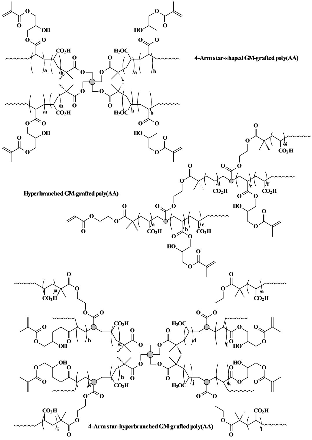
Figure 2. Structure scheme of star-shaped, hyperbranched and star-hyperbranched poly(AA).
3Pl/2bd2, where P = the load at fracture, l = the distance between the two supports, b = the breadth of the specimen, and d = the depth of the specimen. FT was calculated from the equation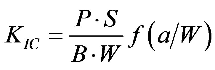 , where KIC =
the index for FT, P = the load at fracture, S = the distance between supports, a = the length of notch, B = the thickness, and W = the width of specimen. The f is a function of (a/W), as shown below [24] :

The hardness test was performed on a micro-hardness tester (LM-100, LECO Corporation, MI) using a diamond indenter with 25 g load and 30 s dwell time [25] . Knoop hardness number (KHN) was averaged from six readings for each sample.
The wear test was conducted using the Oregon Health Science University (OHSU) oral wear simulator (Proto-tech, Portland, OR) employing ceramic antagonists to produce both abrasive and attritional wear [26] [27] . The test was performed following the published procedures [28] with a slight modification. Briefly, after polishing with sand paper, the specimen embedded in the mold was tightened into an individual wear chamber, followed by the addition of a food like slurry consisting of 1.0 g ground poppy seed, 0.5 g PMMA powder and 5 ml distilled water. The abrasion force was set at 20 N and the attrition force at 90 N. The specimen was subject to 70,000 wear cycles at a frequency of 1 Hz. The worn specimen was analyzed using an optical surface profilometer (Surftronic 3+, Taylor Hobson Ltd., Leicester, England) [28] . Both abrasive and attritional wear depths were obtained per manufacturer’s recommendation, averaging from three traces. Four specimens were tested to obtain a mean wear value for each material.
2.7. Statistical Analysis
One-way analysis of variance (ANOVA) with the post hoc Tukey-Kramer multiple-range test was used to determine significant differences of the measured properties among the materials in each group. A level of α = 0.05 was used for statistical significance.
3. Results and Discussion
3.1. Characterization
The chemical shifts (ppm) from the 1HNMR spectra of t-BA, 4-arm BIBB, BIEA, star-hyperbranched poly(t-BA), poly(AA) and GM-grafted poly(AA) were listed below: (a) t-BA: 1.50 (-CH3, 9 H), 5.68 (=CH2, 1 H), 6.00 (=CHCO-, 1 H) and 6.27 (=CH2, 1 H); (b) 4-arm BIBB: 1.93 (-C(CH3)2, 24 H) and 4.32 (CCH2O, 8 H); (c) BIEA: 1.86 (-CH3, 6 H), 4.36 (-OCH2CH2O-, 4 H), 5.82 (=CH2, 1 H), 6.08 (=CHCO-, 1 H) and 6.36 (=CH2, 1 H); (d) poly(t-BA): 1.38 (-CH3), 1.78 (-CH2-) and 2.15 (-CHCO-); (e) poly(AA): 1.51 (-CH3), 2.36 (-CH2-), 3.37 (-CHCO-) and 12.24 (-COOH); and (f) GM-grafted poly(AA): 1.50 (-CH3), 2.25 (-CH2-), 3.25 (OH), 3.35 (-CHCO-), 3.80-4.15 (-OCH2-) 5.67 (CH2=), 6.06 (CH2=) and 12.22 (-COOH). The characteristic chemical shifts at 3.25 (OH), 5.67 (CH2=) and 6.06 (CH2=) identified the difference between the star-hyperbranched poly(AA) and GM-grafted poly(AA).
3.2. Polymerization Kinetics
The ATRP polymerization kinetics of poly(t-BA) was studied using 1HNMR. After the polymerization was initiated, aliquots were retrieved from each reaction system at different time intervals, dissolved in CDCl3 and immediately measured with 1HNMR. Figure 3 shows a set of kinetic plot of monomer to polymer conversion versus time and a semi-logarithmic plot of ln ([M]0/[M]) versus time, where [M]0 = the initial concentration of the monomer and [M] = the monomer concentration at any time. The conversion was calculated by comparison of the peak integrations between 6.27 (HC=C) and 1.2-1.6 ppm (-CH3). The values of ln ([M]0/[M]) were obtained from ln[1/(1-conversion%)]. Figure 3(a) shows a kinetic plot for the 4-arm star-shapred poly(t-BA). Two stages were found from the plot of ln ([M]0/[M]) versus time: a linear plot with 0.682 (slope) and 0.989 (R2) within 3 h after the reaction was initiated and a deviated plot with a little steeper slope after 3 h. The conversion reached 91, 95 and 97% at 3, 4 and 5 h. Figure 3(b)shows a kinetic plot for the hyperbranched poly(t-BA). A similar plot to Figure 3(a) is found: a linear plot with 0.486 (slope) and 0.995 (R2) within 3 h after the reaction was initiated and a deviated plot with a steeper slope after 3 h. The conversion reached 78, 96 and 99.7% at 3, 4 and 5 h, indicating that the reaction was initially slow and then accelerated after 3 h. Figure 3(c) shows a kinetic
 (a)
(a)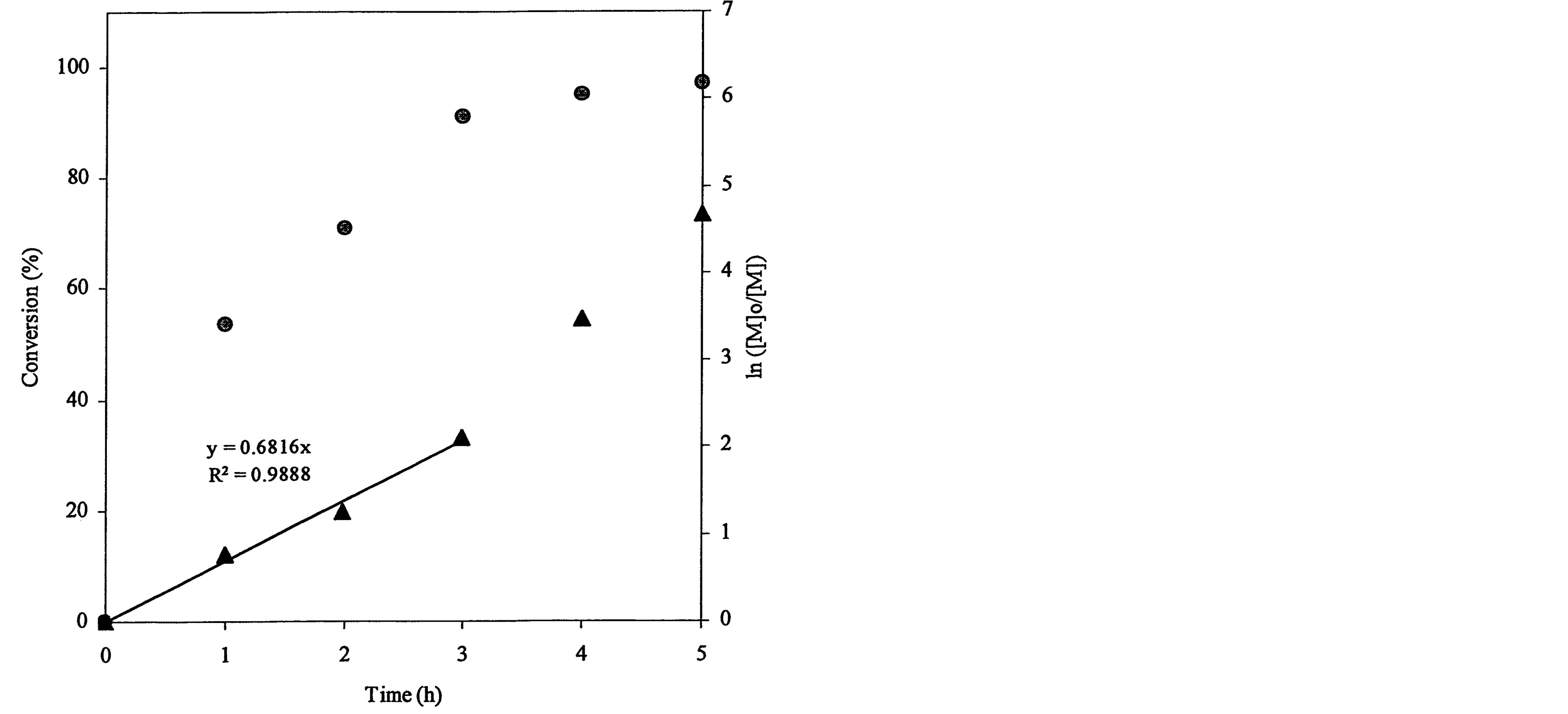 (b)
(b) (c)
(c)
Figure 3. Conversions and kinetic plots of the star-shaped, hyperbranched and star-hyperbranched poly(t-BA) derived from the NMR spectra (upper curve = conversion vs. time and lower curve = ln ([M]o/[M]) vs. time): (a) 4-Arm star-shaped poly(t-BA), initiator/t-BA = 0.5% (BIBB); (b) Hyperbranched poly(t-BA), initiator/t-BA = 2% (BIEA); (c) 4-Arm star-hyperbranched poly(t-BA), initiator/t-BA = 0.25% (4-arm BIBB)-1% (BIEA).
plot for the 4-arm star-hyperbranched poly(t-BA): a linear plot with 0.455 (slope) and 0.957 (R2) within 3 h and a deviated plot with a steeper slope after 3 h. The conversion reached 78, 98.7 and 99.8% at 3, 4 and 5 h, again indicating that the reaction was accelerated after 3 h.
The plot of ln([M]0/[M]) vs. time can be used to examine whether the reaction follows the first-order kinetics and to calculate the apparent rate constant k or the slop of the plot. It is known that ATRP reaction generally exhibits the first-order kinetics due to persistent radical effect [29] and its kinetic semi-logarithmic plot versus time is expected to be linear. Regarding the polymer synthesis (see Figure 3), none of the three polymers followed the first-order kinetics. They all went through the two stages, i.e., a linear portion before 3 h and a deviated plot after 3 h. However, compared to the star-shaped poly(AA) (Figure 3(a)), either hyperbranched or star-hyperbranched poly(AA) showed a significantly deviated plot from linearity after 3 h with an accelerated polymerization fashion (Figures 3(b) and (c)). The plausible reason may be explained below. For synthesis of the star-shaped polymer, a chain grows and extends from each individual reactive BIBB site and thus no branching is expected. However, for synthesis of both hyperbranched and star-hyperbranched polymers, where BIEA was used as an ATRP initiator for branching formation, the case is quite different. At a lower conversion, a chain growth followed a regular pattern due to a lower viscosity of the reaction system and thus obeys the first order kinetics. At a higher conversion, however, the mobility of the extended polymer chains was significantly reduced due to increased MW and viscosity (In fact, the solution viscosity was observed significantly higher at the later stage). Furthermore, since the acrylate groups on BIEA (ATRP initiator for the hyperbranched polymer synthesis) were located at the end of extended polymer chains, their reactivity as a commoner with the propagating radicals were reduced as well. These two reasons might lead to reduction of the termination constant and thus auto acceleration of the polymerization. That is why the plot deviated from linearity for synthesis of both hyperbranched and star-hyperbranched polymers. Furthermore, by comparing the slop or k value of the plot, lower values were observed for both hyperbrached (0.486) and star-hyperbranched (0.455) polymer synthesis as compared to the star-shaped (0.682) polymer synthesis, suggesting that at the early stage the propagation of the latter is faster than the former two.
Figure 4(a) shows the effect of the arm number and the initiator concentration on polymerization kinetics. It was found that each plot remained linear until the ln([M]0/[M]) value exceeded 2.0. The slopes and R2-values of the linear portions on the curves are 0.838 and 0.999, 2.411 and 0.998, and 4.744 and 0.998 for the ATRP reactions of t-BA initiated with 3-arm, 4-arm and 6-arm initiators, respectively. Figure 4(b) shows the effect of the 6-arm initiator concentration on polymerization kinetics. It was found that each plot remained linear until the ln ([M]0/[M]) value exceeded 1.5. The slopes and R2-values of the linear portions on the curves are 4.744 and 0.998, 1.317 and 0.994, and 0.362 and 0.999 for the 6-arm initiator concentration of 1%, 0.5% and 0.25%, respectively.
Apparently all the plots exhibited a high linearity at the early stage of the polymerization (conversion = 80%). The R2 values (0.994 to 0.999) indicate that the reactivity of the active sites remained constant during this stage. Once the monomer conversion reached 80%, the plot started to deviate from the linearity. This behavior may be explained below: 1) when the conversion was above 80%, the active sites moved to the ends of the long polymer chains, thus limiting their mobility; and 2) the viscosity of the reaction system became higher and higher as the polymer chains grew longer and longer. Both reasons led to reduction of the termination constant, resulting in an accelerated polymerization [30] [31] .
From Figure 4(a), the slop or k value of the plot for the polymerization was in the decreasing order: 6-arm initiator (4.74) > 4-arm initiator (2.41) > 3-arm initiator (0.838). This can be attributed to the reason that more arms indicate more initiating sites, thus leading to a faster ATRP reaction. From Figure 4(b), apparently the polymerization with a higher initiator concentration showed a higher k value (4.74 for 1%, 1.32 for 0.5% and 0.36 for 0.25%), indicating that the higher the initiator concentration, the faster the ATRP reaction. The results suggest that both arm number and initiator concentration increase the polymerization rate.
3.3. Effects of Arm Number and Branching on MW, MWD and Viscosity
The measured MW and polydispersity index (PDI) (equivalent to MW distribution or MWD) of the synthesized star, hyperbranched and star-hyperbranched poly(t-BA) and the viscosity values of the corresponding poly(AA) aqueous solutions are shown in Table 1. For both star-shaped and hyperbranched polymers, increasing either arm number or branching did not change MWD much but significantly decreased the solution viscosity. For the star-hyperbranched polymers, increasing arm number or branching increased the MWD but also decreased the solution viscosity significantly. It is concluded that increasing arm number and branching in the polymer favors a lower solution viscosity. For the effect of the star-shaped polymers, this is logical because the 6-arm star polymer is even more like a sphere as compared to 3 and 4-arm star polymers. For the effect of the branching, hyperbranching cannot be considered as a simple branching; instead each branching unit should be regarded as a 3-arm star core (see Figure 2) due to its sp3 tetrahedral structure. Thus the hyperbranched poly(AA) can be regarded as several linked 3-arm star poly(AA). That may be why either hyperbranched or star-branched polymers showed higher viscosity values than the star-shaped poly(AA). It is known in dental clinics that cement mixing requires a workable solution viscosity for the polymer solution. Relatively low solution viscosity favors cement mixing clinically because it can reduce the probability of forming flaws or defects, thus enhancing the mechanical strength [1] [2] [3] [8] . Therefore, without compromising the mechanical strengths a polymer solution with a lower viscosity would be favorable to dental clinics.
 (a)
(a)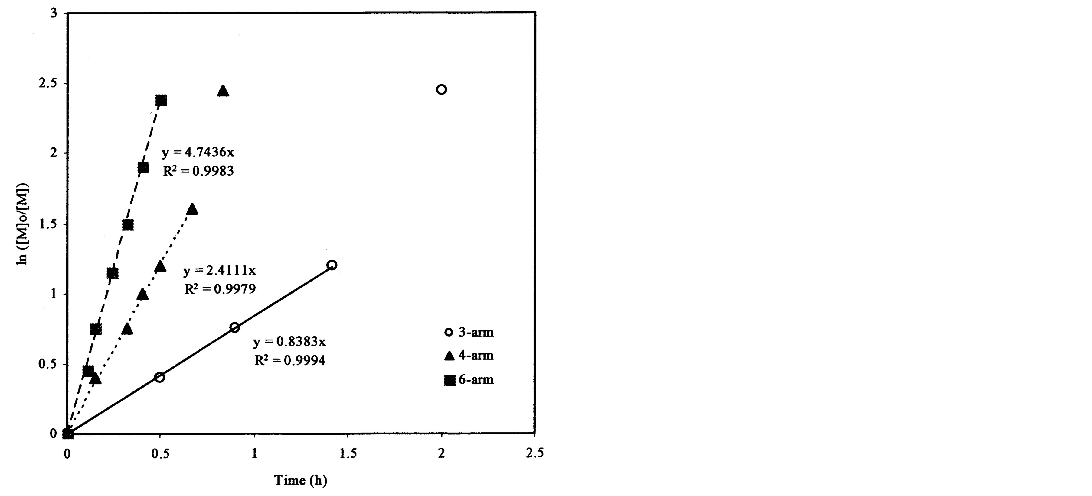 (b)
(b)
Figure 4. Kinetic plots of ln([M]0/[M]) vs. time for the polymerization of t-BA: (a) Initiation with 3-, 4- and 6-arm initiators: initiator/t-BA = 1% (by mole); (b) Initiation with 0.25%, 0.5% and 1% of 6-arm initiator/t-BA.

Table 1. MWs, molecular weight distribution and viscosity of the synthesized polymers1.
1Mn, Mw and PDI of poly(t-BA) were measured by GPC, PDI = polydispersity index, and viscosity of the GM-tethered poly(AA) in water (polymer/water or P/W ratio = 60/40, by weight) was determined at 23˚C; 2S, H and SH = star-shaped, hyperbranched and star-hyperbranched polymers, respectively, LDB, MDB and HDB represent low, medium and high degree of branching; 3Initiator = 2-bromo-2-methyl-propionic acid methyl ester (2% by mole); 4Initiator = 3-, 4- or 6-arm star-shaped BIBB (1%); 5Initiator = BIEA (2%); 63-, 4- or 6-arm star-shaped BIBB (0.125%) + BIEA where BIEA/star-shaped BIBB = 4; 7Initiators = 4-arm star-shaped BIBB (0.125%) + BIEA where BIEA/star-BIBB = 4, 8 and 16.
3.4. Evaluation
Table 2 shows the effects of the arm number of both star-shaped and star-hyperbranched poly(AA) and branching of both hyperbranched and star-hyperbranched poly(AA) on CS, DTS, FS and compressive modulus of the experimental cements. There seems a trend that increasing the arm number and branching decreased CS, DTS, FS and modulus, although some of the values in each category were not statistically different from one another. Table 3 shows the effects of the arm number and branching of the star-hyperbranched poly(AA) on KHN, FT, abrasion and attrition of the experimental cements. There is also a trend that increasing the arm number and branching decreased KHN, FT, abrasion resistance and attrition resistance, although some of the values in each category were not statistically different from one another. The trend may be attributed to the fact that all the initiators we used in this study are mainly composed of hydrocarbons and bromoesters (see Figures 1 and 2). More arms mean more bromoester groups existing in the star-shaped polymers and so do the hyperbranched polymers. None of these ATRP initiators contain functional groups which could be used for strength enhancement such as carboxyl groups. These bulky hydrophobic initiator cores do not contribute any strength enhancement to the cement system. That may be why the more the initiator in the system, the lower the mechanical strength. Fortunately, these cores did not affect the strength significantly because only 0.25%~3% by mole was used.
Table 4 shows the mean values of CS, modulus, DTS, FS, FT, KHN, abrasion and attrition of the 4-arm star-shaped experimental cement (EXPSGIC), hyperbranched cement (EXPHGIC), and 4-arm star-hyperbranched cement (EXPSHGIC) versus Fuji II LC cement. Apparently, all the experimental cements exhibited significantly higher values than Fuji II LC in all the measured mechanical properties (p < 0.05). EXPGICs were 31% - 53% in CS, 37% - 55% in compressive modulus, 80% - 126% in DTS, 76% - 94% in FS, 4% - 21% in FT and 53% - 96% in KHN higher than Fuji II LC. For wear test, EXPGICs were only 5.4% - 13% of abrasive and
Table 2. Effects of arm number and branching on CS, DTS, FS and modulus of the cements
1Polymers = GM-tethered 4-arm star-shaped (S), hyperbranched (H), or star-hyperbranched (SH) poly(AA) (see details for the initiators in Table 1), GM grafting ratio = 50% (by mole), P/W ratio = 70/30 (by weight), P/L ratio = 2.7 (by weight); 2Modulus = compressive modulus; 3Entries are mean values with standard deviations in parentheses and the mean values with the same letter in each category were not significantly different (p > 0.05). Specimens were conditioned in distilled water at 37˚C for 24 h prior to testing.
Table 3. Effects of arm number and branching on KHN, FT, abrasion and attrition of the cements.
1Polymers = GM-tethered star-hyperbranched poly(AA) and the details were the same as those shown in Table 2; 2Entries are mean values with standard deviations in parentheses and the mean values with the same letter in each category were not significantly different (p > 0.05). Specimens were conditioned in distilled water at 37˚C for 24 h prior to testing.
Table 4. Comparison among Fuji II LC and the experimental GICs1.
1Experimental GICs = EXPSGIC (star-shaped), EXPHGIC (hyperbranched) and EXPSHGIC (star-hyperbranched), where all the polymers = GM tethered poly(AA), GM grafting ratio = 50%, P/W ratio = 70/30 and P/L ratio = 2.7/1, except for the initiators used: 6-arm star-shaped BIBB/t-BA = 1% in EXPSGIC, BIEA/t-BA = 1% in EXPHGIC, and 6-arm star-shaped BIBB (0.25%)-BPEA (1%) in EXPSHGIC; 2Entries are mean values with standard deviations in parentheses and all the mean values in each category were significantly different (p < 0.05). Specimens were conditioned in distilled water at 37˚C for 24 h prior to testing.
6.4% - 12% of attritional wear depths of Fuji II LC in each wear cycle. There is a trend that EXPHGIC showed the highest mechanical strength values, followed by EXPSHGIC, EXPSGIC and Fuji II LC, although there were no statistically significant differences in some of the properties among EXPSGIC, EXPHGIC and EXPSHGIC. The higher mechanical strengths exhibited by these EXPGICs can be attributed to the unique nature of the experimental cement system including components, polymer content and the structures of the polymers. As we know, most commercially available systems contain low MW comonomers such as HEMA or methacrylates or dimethacrylates [4] [13] . Unlike them, the developed experimental GICs were composed of either star-shaped, or hyperbranched or star-hyperbranched poly(AA) polymer, water and initiators. There were no any low MW comonomers in the experimental cement system. In other words, the experimental cement system essentially comprises a monomer-free cement. The polymer aqueous liquid in the experimental cement system contains highly concentrated GM-grafted poly(AA), which provides not only a large quantity of carboxyl groups for salt-bridge formation but also a substantial amount of carbon-carbon double bond (methacrylate) for covalent crosslinks. In contrast, Fuji II LC contains a substantial amount of low MW monomer HEMA (2-hydroxylethyl methacrylate) and other low MW methacrylate or dimethacrylate comonomers, in addition to linear poly(AA) and water [13] . These low MW monomers and oligomers are mainly responsible for the lower strength of the cement.
Figure 5 illustrates representative regions of the fracture surfaces of the selected specimens from Fuji II LC, EXPSGIC, EXPHGIC and EXPSHGIC using SEM. Voids were found in Fuji II LC, EXPSGIC and EXPHGIC. All the experimental cements showed a better surface integration with fillers and rugged surfaces than Fuji II
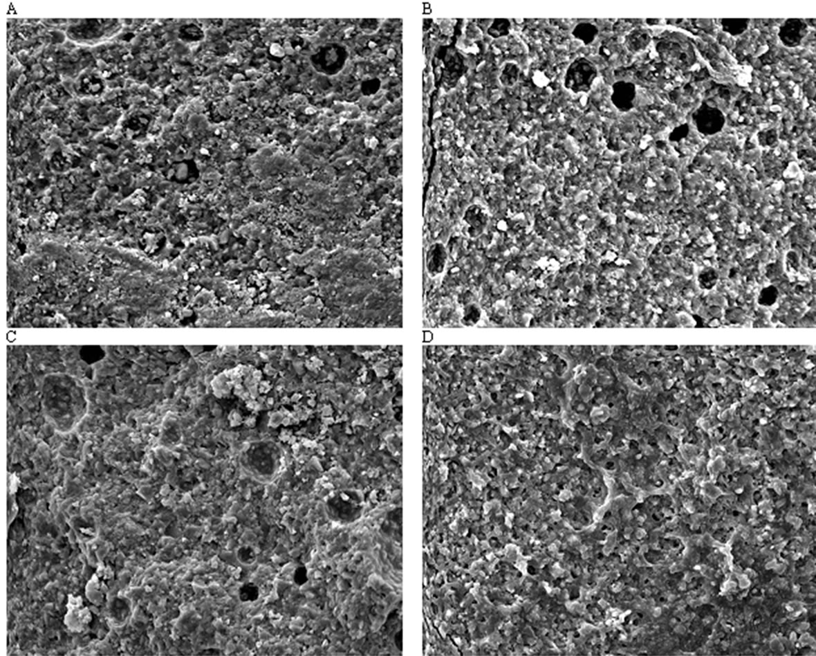
Figure 5. Fracture surface photomicrographs at a magnification of 1500×: (A), (B), (C) and (D) stand for the fracture surface of the specimens from Fuji II LC, EXPSGIC, EXPHGIC and EXPSHGIC after FS testing. Specimens were conditioned in distilled water at 37˚C for 24 h prior to testing
LC. In contrast, Fuji II LC showed more loosely bonded particles, flatter surface, and poorer filler-resin integration. Figure 5 supports the results of the mechanical strengths from Table 4.
Figure 6 shows the effect of aging in water on CS of the experimental cements versus Fuji II LC. Significant increases are observed for all the cements tested from 1 h to 1 d: 17%, 32%, 33% and 32% for Fuji II LC, EXPSGIC, EXPHGIC, and EXPSHGIC. Increases were also found with different aging time: 1) from 1 d to 7 d: Fuji II LC (1%), EXPSGIC (15%), EXPHGIC (4%) and EXPSHGIC (7%); 2) from 1 d to 30 d: Fuji II LC (0%), EXPSGIC (21%), EXPHGIC (8%) and EXPSHGIC (9%). It is well known that GICs increase their strengths in water with time due to constant salt-bridge formation while water slowly penetrates in [32] [33] . Significant CS increases from 1 h to 1 d indicate that salt-bridge formation mainly occurs during a 24 h period. In addition, huge increase (32% - 33%) by EXPGICs versus 17% by Fuji II LC indicates that more carboxylic acids exist in EXPGICs than in Fuji II LC. This can be attributed to the fact that EXPGICs contain more poly(AA) than Fuji II LC. The experimental cement system contains 70% GM-grafted poly(AA) and 30% water in liquid whereas Fuji II LC contains 20% - 30% PAA, 30% - 35% HEMA, 5% -10% dimethacrylates and 20% - 30% water [4] [13] . After 1 d or 24 h aging, Fuji II LC cement showed almost no change in CS, suggesting that the salt-bridge formation in Fuji II LC was complete within 24 h. This result can be well explained with the composition shown above, i.e., a substantial amount of carboxylic acids for salt-bridges are replaced by HEMA and dimethacrylates [13]. On the other hand, a continuous increase in CS by the EXPGICs from 1 d to 7 d or even 1 d to 30 d may be partially attributed to the unique star-shaped, hyperbranched or star-hyperbramched molecular structures. We infer that unlike linear poly(AA), in the star-shaped or hyperbranched or hyperbranched poly(AA)-composed
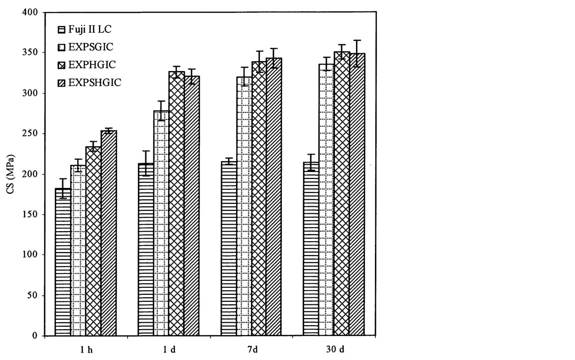
Figure 6. Effect of aging in water on CS: EXPSGIC, EXPHGIC and EXPSHGIC represent the experimental cements composed of the star-shaped, hyperbranched and star-hyperbranched polymers, respectively. The formulations are shown in Tables 2 and 4. All the specimens were conditioned in distilled water at 37˚C prior to testing
cements, the salt-bridge formation may start gradually from the outside towards inside, which requires more time to complete. That is why a continuous increase in CS from 1 d to 7 d or even 30 d was observed.
4. Conclusion
In this study, a new high-strength glass-ionomer cement system composed of poly(AA) with different molecular architectures has been developed and studied. The poly(AA) polymers were synthesized via ATRP technique. The results showed that unlike the star-shaped polymer synthesis both hyperbranched and star-hyperbranched polymers syntheses proceed slowly at the early stage but accelerate at the later stage. The higher the arm number and initiator concentration are, the faster the ATRP reaction was. It was also found that the higher the arm number and branching that the polymer had, the lower the viscosity of the polymer aqueous solution is and the lower the mechanical strengths of the formed cement are. The mechanical strengths of three synthesized polymers composed of EXPGICs were very similar to each other but much higher than those of Fuji II LC. EXPGICs were 31% - 53% in CS, 37% - 55% in compressive modulus, 80% - 126% in DTS, 76% - 94% in FS, 4% - 21% in FT and 53% - 96% in KHN higher than Fuji II LC. For wear test, EXPGICs were only 5.4% - 13% of abrasive and 6.4% - 12% of attritional wear depths of Fuji II LC in each wear cycle. The one-month aging study also showed that all EXPGICs increased their CS continuously during 30 days, unlike Fuji II LC.
Acknowledgements
This work was sponsored by NIH grant DE020614.
References
- Smith, D.C. (1998) Development of Glass-Ionomer Cement Systems. Biomaterials, 9, 467-478. http://dx.doi.org/10.1016/S0142-9612(97)00126-9
- Wilson, A.D. and McLean, J.W. (1988) Glass-Ionomer Cements. Quintessence Publ Co., Chicago.
- Davidson, C.L. and Mjör, I.A. (1999) Advances in Glass-Ionomer Cements. Quintessence Publ Co., Chicago.
- Wilson, A.D. (1990) Resin-Modified Glass-Ionomer Cement. The International Journal of Prosthodontics, 3, 425-429.
- Hotz, P., McLean, J.W., Sced, I. and Wilson, A.D. (1977) The Bonding of Glass-Ionomer Cements to Metal and Tooth Substrates. British Dental Journal, 142, 41-47. http://dx.doi.org/10.1038/sj.bdj.4803864
- Lacefield, W.R., Reindl, M.C. and Retief, D.H. (1985) Tensile Bond Strength of a Glass-Ionomer Cement. The Journal of Prosthetic Dentistry, 53, 194-198. http://dx.doi.org/10.1016/0022-3913(85)90108-8
- Forsten, L. (1977) Fluoride Release from a Glass-Ionomer Cement. Scandinavian Journal of Dental Research, 85, 503-504.
- Craig, R.G. (1997) Restorative Dental Materials. 10th Edition, Mosby-Year Book, Inc., St Louis.
- Nicholson, J.W., Braybrook, J.H. and Wasson, E.A. (1991) The Biocompatibility of Glass-Poly(alkenoate) GlassIonomer Cements: A Review. Journal of Biomaterials Science. Polymer Edition, 2, 277-285. http://dx.doi.org/10.1163/156856291X00179
- Hume, W.R. and Mount, G.J. (1988) In Vitro Studies on the Potential for Pulpal Cytotoxicity of Glass-Ionomer Cements. Journal of Dental Research, 67, 915-918. http://dx.doi.org/10.1177/00220345880670060501
- Guggenberger, R., May, R. and Stefan, K.P. (1998) New Trends in Glass-Ionomer Chemistry. Biomaterials, 19, 479- 483. http://dx.doi.org/10.1016/S0142-9612(97)00127-0
- Mitra, S.B. (1991) Adhesion to Dentin and Physical Properties of A Light-Cured Glass-Ionomer Liner/Base. Journal of Dental Research, 70, 72-74. http://dx.doi.org/10.1177/00220345910700011201
- Momoi, Y., Hirosaki, K., Kohno, A. and McCabe, J.F. (1995) Flexural Properties of Resin-Modified Hybrid GlassIonomers in Comparison with Conventional Acid-Base Glass-Ionomers. Dental Materials Journal, 14, 109-119. http://dx.doi.org/10.4012/dmj.14.109
- Xie, D., Culbertson, B.M. and Johnston, W.M. (1998) Formulations of Light-Curable Glass-Ionomer Cements Containing N-Vinylpyrrolidone. Journal of Macromolecular Science, Part A Pure and Applied Chemistry, A35, 1631-1650. http://dx.doi.org/10.1080/10601329808000976
- Xie, D., Wu, W., Puckett, A., Farmer, B. and Mays, J. (2004) Novel Resin-Modified Glass-Ionomer Cements with Improved Flexural Strength and Ease of Handling. European Polymer Journal, 40, 343-351. http://dx.doi.org/10.1016/j.eurpolymj.2003.09.022
- Kao, E.C., Culbertson, B.M. and Xie, D. (1996) Preparation of Glass-Ionomer Cement Using N-Acryloyl-Substituted Amino Acid Monomers: Evaluation of Physical Properties. Dental Materials, 12, 44-51. http://dx.doi.org/10.1016/S0109-5641(96)80063-7
- Xie, D., Chung, I.D., Wu, W., Lemons, J., Puckett, A. and Mays, J. (2004) An Amino Acid Modified and Non-HEMA Containing Glass-Ionomer Cement. Biomaterials, 25, 1825-1830. http://dx.doi.org/10.1016/j.biomaterials.2003.08.033
- Xie, D., Culbertson, B.M. and Johnston, W.M. (1998) Improved Flexural Strength of N-Vinylpyrrolidone Modified Acrylic Acid Copolymers for Glass-Ionomers. Journal of Macromolecular Science, Part A Pure and Applied Chemistry, A35, 1615-1629. http://dx.doi.org/10.1080/10601329808000975
- Bahadur, P. and Sastry, N.V. (2002) Principles of Polymer Science. CRC Press, Boca Raton.
- Huang, C.F., Lee, H.F., Kuo, S.W., Xu, H. and Chang, F.C. (2004) Star Polymers via Atom Transfer Radical Polymerization from Adamantine-Based Cores. Polymer, 45, 2261-2269. http://dx.doi.org/10.1016/j.polymer.2004.01.051
- Xie, D., Park, J.G. and Zhao, J. (2007) Synthesis and Preparation of Novel 4-Arm Star-Shape Poly(carboxylic acid)s for Improved Light-Cured Glass-Ionomer Cements. Dental Materials, 23, 395-403. http://dx.doi.org/10.1016/j.dental.2006.02.008
- Xie, D., Yang, Y., Zhao, J., Park, J.G. and Zhang, J.T. (2007) A Novel Comonomer-Free Light-Cured Glass-Ionomer Cement for Reduced Cytotoxicity and Enhanced Mechanical Strength. Dental Materials, 23, 994-1003. http://dx.doi.org/10.1016/j.dental.2006.09.001
- Zhao, J. and Xie, D. (2011) A Novel Hyperbranched Poly(acrylic acid) for Improved Resin-Modified Glass-Ionomer Restoratives. Dental Materials, 27, 478-486. http://dx.doi.org/10.1016/j.dental.2011.02.005
- Johnson, W.W., Dhuru, V.B. and Brantley, W.A. (1993) Composite Microfiller Content and Its Effect on Fracture Toughness and Diametral Tensile Strength. Dental Materials, 9, 95-98. http://dx.doi.org/10.1016/0109-5641(93)90082-2
- Xie, D., Brantley, W.A., Culbertson, B.M. and Wang, G. (2000) Mechanical Properties and Microstructures of GlassIonomer Cements. Dental Materials, 16, 129-138. http://dx.doi.org/10.1016/S0109-5641(99)00093-7
- Dowling, A.H. and Fleming, G.J.P. (2007) The Impact of Montmorillonite Clay Addition on the in Vitro Wear Resistance of a Glass-Ionomer Restorative. Journal of Dentistry, 35, 309-317. http://dx.doi.org/10.1016/j.jdent.2006.10.002
- Condon, J.R. and Ferracane, J.L. (1996) Evaluation of Composite Wear with a New Multi-Mode Oral Wear Simulator. Dental Materials, 12, 218-226. http://dx.doi.org/10.1016/S0109-5641(96)80026-1
- Turssi, C.P., Ferracane, J.L. and Vogel, K. (2005) Filler Features and Their Effects on Wear and Degree of Conversion of Particulate Dental Resin Composites. Biomaterials, 26, 4932-4937. http://dx.doi.org/10.1016/j.biomaterials.2005.01.026
- Matyjaszewski, K. and Xia, J. (2001) Atom Transfer Radical Polymerization. Chemical Reviews, 101, 2921-2990. http://dx.doi.org/10.1021/cr940534g
- Shipp, D.A. and Matyjaszewski, K. (1999) Kinetic Analysis of Controlled/“Living” Radical Polymerizations by Simulations. 1. The Importance of Diffusion-Controlled Reactions. Macromolecules, 32, 2948. http://dx.doi.org/10.1021/ma9819135
- Shipp, D.A. and Matyjaszewski, K. (2000) Kinetic Analysis of Controlled/“Living” Radical Polymerizations by Simulations. 2. Apparent External Orders of Reactants in Atom Transfer Radical Polymerization. Macromolecules, 33, 1553-1559. http://dx.doi.org/10.1021/ma991651m
- Cattani-Lorente, M.A., Godin, C. and Meyer, J.M. (1994) Mechanical Behavior of Glass ionomer Cements Affected by Long-term Storage in Water. Dental Materials, 10, 37-44. http://dx.doi.org/10.1016/0109-5641(94)90020-5
NOTES

*Corresponding author.