Journal of Computer and Communications
Vol.04 No.10(2016), Article ID:69618,12 pages
10.4236/jcc.2016.410001
Quadcopter Design for Payload Delivery
Gordon Ononiwu, Ondoma Onojo, Oliver Ozioko, Onyebuchi Nosiri
Department of Electrical/Electronic Engineering, Federal University of Technology, Owerri, Nigeria

Copyright © 2016 by authors and Scientific Research Publishing Inc.
This work is licensed under the Creative Commons Attribution International License (CC BY).
http://creativecommons.org/licenses/by/4.0/


Received 19 June 2016; accepted 7 August 2016; published 10 August 2016
ABSTRACT
This paper presents the design and implementation of a quadcopter capable of payload delivery. A quadcopter is a unique unmanned aerial vehicle which has the capability of vertical take-off and landing. In this design, the quadcopter was controlled wirelessly from a ground control station using radio frequency. It was modeled mathematically considering its attitude and altitude, and a simulation carried out in MATLAB by designing a proportional Integral Derivative (PID) controller was applied to a mathematical model. The PID controller parameters were then applied to the real system. Finally, the output of the simulation and the prototype were compared both in the presence and absence of disturbances. The results showed that the quadcopter was stable and able to compensate for the external disturbances.
Keywords:
Quadcopter, PID, Controller, Payload, Delivery, Unmanned, Aerial, Vehicle

1. Introduction
Quadcopters are unique unmanned aerial vehicles which have a vertical take-off and landing ability [1] . In the past, it was primarily used in the military, where it was deployed in hostile territory, to reduce pilot losses. The recent reduction in cost and feature size of semi-conductor logic has led to the application of quadcopters in many other areas like weather monitoring, forest fire detection, traffic control, cargo transport, emergency search and rescue, communication relaying, etc. Quadcopters operate in fixed rotor propulsion mode, an advantage over the traditional helicopter. They have four rotors which are arranged in such a way that rotors on transverse ends rotate in the same direction, while the other two operate in the opposite direction [1] . Changing the parameters of the attitude (roll, pitch and yaw), and altitude determines the behavior and position of the quadcopter. The throttle on each rotor changes its attitude. The UAVs can be broadly classified into two categories: fixed wing versus rotary wing, each with their own strengths and weaknesses. For instance, the fixed-wing UAVs usually have high speed, and heavy payload, but they must maintain a continuous forward motion to remain in the air [2] .
The applications for quadcopters have recently grown significantly, and related works are presented here. [3] presented an altitude controller design for UAVs in real time applications. The author described a controller design method for the hovering control of UAVs and automatic vertical take-off systems. In 2012, the attitude and altitude dynamics of an outdoor quadrotor were controlled using two different structures of proportional integral derivative (PID) controllers [4] . The tests showed that the two structures were successful. [5] presents a Quadcopter for surveillance monitoring. In [6] , the design and control of VertiKUL, a Vertical Take-Off and Landing (VTOL) transitioning tail-sitter Unmanned Aerial Vehicle (UAV) was presented. The UAV is capable of hover flight and forward flight, and its main application is for parcel delivery.
2. Methodology
In this work, aquadcopter was first modeled mathematically, after which a simulation was carried out in MATLAB by designing a PID controller, which was applied to the mathematical model. The PID controller parameters were then applied to the real system. Finally, the output of the simulation and the real system were compared. In this paper, attitude and altitude dynamics of a quadcopter were considered. Therefore, roll, pitch, yaw, and altitude dynamics were modeled.
2.1. Mathematical Model of Attitude Dynamics
One of the aims of the work is to stabilize the quadcopter in the hovering condition. The following assumptions were made [4] - [7] : i) System structure is supposed to be rigid and symmetrical. ii) Earth fixed reference frame is assumed to be inertial. iii)The rotors are rigid, i.e. no blade flapping occurs.
Attitude of the quadcopter is defined by roll, pitch and yaw angles; namely ,
,  , and
, and , respectively. Angular velocity components in body reference frame are p, q, and r, respectively. F1, F2, F3, and F4 are the thrust forces from the four motors, which are generated by propellers. Axes and states are represented in Figure 1. It is possible to obtain a rotation matrix with the following equation:
 (2.1)
(2.1)
where  is the matrix transformation dynamics of the model quadcopter moving from landing position to a fixed position in space.
Therefore, substituting ,
,  , and
, and  into Equation (2.1), we get the system matrix:
 . (2.2)
The angular velocity of the quadcopter can be written as:
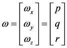 . (2.3)
It is possible to write state equations of the Euler angles in terms of angular velocity components, p, q, and r by using rotation matrices.
 (2.4)
(2.4)
 (2.5)
(2.5)
 . (2.6)
Inertia matrix can be written below as:
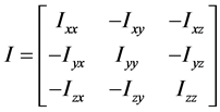 . (2.7)
 (a)
(a) (b)
(b)
Figure 1. Schematic representation of the system.
Inertia matrix, I is assumed to be a diagonal matrix (i.e. the mass products of inertia terms are assumed to be 0). Thrust forces generated by each motor-propeller pair are denoted by F1, F2, F3 and F4. Therefore, resultant moments about roll, pitch and yaw axes are given below:
 (2.8)
(2.8)
 (2.9)
(2.9)
 . (2.10)
Therefore,
 . (2.11)
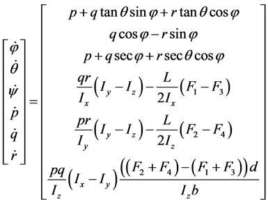
Hence, state vector and state equations considering the yaw, roll and the pitch dynamics of the platform are expressed below:
 (2.12)
 . (2.13)
Also, by applying the force and moment balance laws, we have the following quadcopter motion formulation:
 (2.14)
 (2.15)
 (2.16)
where Ki is the drag coefficient (assume zero since drag is negligible at low speed).
The angle movement of Quadcopter is given by
 (2.17)
 . (2.18)
2.2. Controller Input
Quadcopter has four controller input U1, U2, U3, and U4.
 (2.19)
 (2.20)
 (2.21)
 (2.22)
where,


 .
.
The second derivative of Euler angles are:
 (2.23)
 (2.24)
 . (2.25)
2.3. Motor and Propeller Model
Brushless motors are used as the actuators of propellers of the quadcopter. Four brushless motors in the system are driven via Electronic Speed Controllers (ESC). ESC’s converts PWM signals into a three-phased signal, which rotates the motor continuously. Motor and propeller unit models are identified experimentally. These models are algebraic, steady state ones. Thrust force generated due to the rotation of propellers can be calculated with the equation given below:
 (2.26)
where b is thrust factor which is determined experimentally.
2.4. Mathematical Model of Altitude Dynamics
Total thrust force and weights are the acting forces in z direction. Translational acceleration of the quadcopterin z-axis can be obtained, using the following formula;
 . (2.27)
This equation reveals position in z-axis and velocity in z-axis as two states.
2.5. The PID Controller Design
The PID is a popular way of controlling the quadcopter, and one widely used strategy to control a quadcopter with a PID is to create an individual closed-loop system for each independent axis of each sensor. That is, we would have the same structure depicted in Figure 2 for each sensor axis where  would be the sensor output (angular velocity or acceleration of each axis) and
  the desired value to that axis. This way we would have three different PID controllers for the gyroscope (one for each axis) and the input to each control loop would be an angular velocity reference. That is, making all references equal to zero would make the quadcopter preserve all its rotation angles. Other three distinct PIDs would then be used to control the accelerometer axes. Therefore, setting zero to x and z axes would make the quadcopter hover (all weight force would be concentrated in y axis).
Another widely used strategy is to mix the accelerometer and gyroscope signals to find a single angle value for each axis. That is, combining the gyroscope information with the accelerometer information, one can find a unique angle value for each axis that can represent an absolute angle of rotation or a variation with respect to the previous time step. Therefore, one can use a total of only three closed-loop systems instead of six. Also, there

Figure 2. A typical PID controller internal blocks.
are three multiple ways of combining those signals, and the control system efficiency will directly depend on which way is chosen. Since the sensors can have errors (e.g. noise and drift), a method that minimizes the main problems of each sensor is chosen and the best features of each can be combined.
Therefore, the control signals generated by each closed-loop structure must be combined before sending to the motors. A commonly adopted way of combining those signals is given below:
 (2.28)
 (2.29)
 (2.30)
 (2.31)
where,  signal sent to the
  motor,
  throttle signal and
  control signals (for pitch, roll and yaw axes respectively)
It can be seen in the equations above that those signals are used in a differential mode due to the plant symmetry. Thus, another important detail is that the signals of each term inside each equation depends on each axis reference (e.g. whether positive pitch rotation is clockwise or counter-clockwise) as well as where each motor is positioned. So one must know the motor configuration (whether plus + or cross ×) before writing the equations. Finally, each motor will be individually controlled in an open-loop configuration which can already lead us to a flyable quadcopter.
3. Simulation
The quadcopter design details were used to produce a model to be constructed in the simulation window. Some effects (like aerodynamic effects such as blade flapping) were ignored or dramatically simplified, thus, a limitation to the model. The system model contains five major blocks (systems) each containing its own subsystem or unit blocks that describe the overall system dynamics of our quadcopter. The system blocks include: i) Path Command block; ii) Position Controller block; iii) Attitude Controller block; iv) Quadcopter Control mixing block; v) Quadcopter Dynamics block.
3.1. Path Command and Position Controller
The path command block is used to set the desired position of quadcopter in terms of x, y and z coordinates as well as the yaw (for directioning on the x-y plane). These parameters serve as the set points for the position controller. These variables are loaded as Matlab codes into the simulation through the MATLAB workspace. The position controller takes inputs from the Path command as its set point, and also receives the current position (state) of the quadcopter as feedback. It then compares this feedback with the set point to give the error.
The position error in the body frame is computed, and maps the body frame desired velocity. This desired velocity is then mapped to a desired attitude. The essence of this rotation is because the Inertial-frame velocity is used as the state to be controlled (Path command input).
3.2. The Attitude Controller
The attitude controller, like the position controller, takes feedback from the output of the system as one of its inputs, but takes its second input from the position controller. This block contains the full proportional integral derivative (PID) controller which does the final attitude correction. The feedback to this block contains the current attitude, and angular velocity of the quadcopter in x, y and z axes. The controller essentially compares the current state with the set point, and attempts to bring these various parameters to the set point. The integral part of the PID ensures that the parameters remain at set point once achieved.
Figure 3(a) and Figure 3(b) are the Simulink blocks for Pitch and Yaw, including their corresponding attitude correction outputs.
3.3. Quadcopter Control Mixing
There are two quadcopter configurations available, the quad + configuration and the quad × configuration. The
 (a)
(a) (b)
(b)
Figure 3. (a) Simulink block for the pitch (Theta) correction; (b) Simulink block for the yaw (Psi) correction.
quadcopter control mixing block does the control signal mixing depending on the quadcopter configuration used (plus + or cross ×). It gets the corrected parameters for Pitch ( ), Roll (
 ), Yaw (
 ) and Altitude (Z) from the attitude controller and generates the necessary throttle commands to actuate each motor (m1, m2, m3, m4).
The equations below are used for the control signal mixing of a quad × configuration.
 (3.1)
(3.1)
 (3.2)
(3.2)
 (3.3)
(3.3)
 . (3.4)
3.4. Quadcopter Dynamics
The quadcopter dynamics block contains two major subsystem blocks: The motor dynamics block, and The State Equations block. The Primary function of the Motor dynamics block is to convert the percentage throttle command to the motor RPM.
The motor dynamics block contains the state space model;
 (3.5)
(3.5)
 (3.6)
(3.6)
where,  ,
, 
 ,
, 

The four RPM values generated are fed into the State equations block which contains a level two S-function block, where the flight dynamic state equations are loaded. This S-function is written in MATLAB. The S-function block holds the initial conditions (Table 1) used for the simulation. Its parameters are the quadcopter model functions and the input initial conditions. The outputs,  describes the physical behavior of the quadcopter.
The main function of the S-function block is to use various parameters fed into it, to calculate the quadcopter outputs (Angular velocities, linear velocities, position (along the x, y and z axes) and attitude (yaw, pitch and roll)) which are then used for the simulation plots and 3D animation. Also, a disturbance block was added as input to the S-function block to simulate for response to external forces which might act on the quadcopter body during flight and how it can compensate and recover from these disturbances whilst still trying to maintain flight stability (set point).
The data used for the quadcopter simulation was based on the design model presented. The individual parameters of the components that make up the quadcopter were carefully calculated. Some parameters such as Torque, Thrust and Time Constants where estimated from already measured data of a similar system. This estimation is due to the unavailability of necessary test bench (and instruments) required to carefully monitor and measure these parameters. Since our design model is a quadcopter for payload delivery, our simulation focused on the following: 1) Load test (maximum allowable load on-board); 2) Hover test (with load and without load); 3) Disturbance test (with load and without load).
The PID Control gains were carefully tuned and the appropriate gain value was chosen based on the simulation results obtained. The PID gains used in the Attitude controller are presented in Table 1 while the PD gains of the position controller are presented in Table 2.
4. Simulation Results and Discussion
The simulation was run for 60 seconds and several graphs were generated. Figure 4 shows the result of the simulation with no external disturbance added. The Path command was such that the quadcopter will move a diamond-shaped path. P, Q and R are angular velocities about the X, Y and Z axes respectively; Phi, theta and Psi are the Roll, Pitch and Yaw angles;
U, V and W are the translational velocities along the X, Y and Z axes respectively; X, Y, and Z define the position of the quadcopter along the X, Y and Z axes respectively.

Table 1. Attitude controller PID gains.
Table 2. The position controller PD gains.

Figure 4. Result of the simulation without disturbance.
4.1. Hover Test
The hover simulation of a quadcopter in flight describes its ability to float at/about a fixed point in air. Hover test was done at 10 feet and the results are given below.
The graphs shown in Figure 4 represent a stable system. At first, there was an overshoot, but with time the controller sets each of these parameters to set point.
4.2. Disturbance Test
Disturbance was introduced to the quadcopter flight simulation which could represent the action of external force like wind on the body of the quadcopter while in flight. The graph in Figure 5 represents the system without any disturbance. However, as can be seen from the graph in Figure 6, when a disturbance was introduced, the quadcopter was able to compensate properly. Therefore, the PID controller logic is functional and it can be implemented for the actual system.
The effect of a disturbance to the flight path was further tested with regards to linear and angular velocity is presented in Figure 7. The system acknowledged the disturbance but was able to compensate adequately, and return to a stable flight.
4.3. Load Test
Since the quadcopter design model is for payload delivery, the simulation shows how an increase in the gross mass of the quadcopter affects its motor speed. The result is presented in Figure 8 and Figure 9. Again, the system was able to maintain a stable flight.

Figure 5. Motor throttle vs motor speed.

Figure 6. Motor throttle vs motor speed (disturbance test).
5. Conclusion and Future Work
A stable 1.26 kg quadcopter for payload delivery was designed, simulated and implemented. The design and simulation, which utilized a PID controller, was able to yield results that showed good compensation in the

Figure 7. Simulation result graphs (disturbance test).

Figure 8. Motor throttle vs motor speed (load test).

Figure 9. Simulation result graphs (load test).
presence of external disturbances. The Quad X structural model was used to enable the Quadcopter to gain more speed over a short period of operation, as timely delivery of payload is an important factor. Future study would be to equip the quadcopter with a solar powered system, and to encrypt the communication between the quadcopter and the ground station.
Cite this paper
Gordon Ononiwu,Ondoma Onojo,Oliver Ozioko,Onyebuchi Nosiri, (2016) Quadcopter Design for Payload Delivery. Journal of Computer and Communications,04,1-12. doi: 10.4236/jcc.2016.410001
References
- 1. Min, B.-C., Hong, J.-H. and Matson, E.T. (2011) Adaptive Robust Control (ARC) for an Altitude Control of a Quadrotor Type UAV Carrying an Unknown Payloads. 2011 11th International Conference on Control, Automation and Systems, Korea, 26-29 October 2011, 1147-1151.
- 2. Hochstenbach, M. and Notteboom, C. (2015) Design and Control of an Unmanned Aerial Vehicle for Autonomous Parcel Delivery with Transition from Vertical Take-off to Forward Flight. International Journal of Micro Air Vehicles, 7, 395-405.
http://dx.doi.org/10.1260/1756-8293.7.4.395 - 3. Ononiwu, G.C., Onojo, O.J., Chukwuchekwa, N. and Isu, G.O. (2015) UAV Design for Security Monitoring. International Journal of Emerging Technology & Research, 2, 16-24.
- 4. Guclu, A. (2012) Attitude and Altitude Control of an Outdoor Quadrotor. The Graduate School of Natural and Applied Science, Atilim University, 76.
- 5. Mustapa, M.Z. (2015) Altitude Controller Design for Quadcopter UAV. Jurnal Teknologi.
- 6. Zeng, Y., Zhang, R. and Lim, T.J. (2016) Wireless Communications with Unmanned Aerial Vehicles: Opportunities and Challenges.
- 7. Gupte, S., Mohandas, P.I.T. and Conrad, J.M. (2012) A Survey of Quadrotor Unmanned Aerial Vehicles. 2012 Proceedings of IEEE, Orlando, FL, 15-18 March 2012, 1-6.
http://dx.doi.org/10.1109/secon.2012.6196930