Open Journal of Acoustics
Vol.07 No.02(2017), Article ID:76944,12 pages
10.4236/oja.2017.72004
Characterization of Acoustical Properties of Felt and Carpet Made of Natural and Environmentally Friendly Materials
Haydar Aygün
School of Media Arts and Technology, Southampton Solent University, East Park Terrace, Southampton, UK

Copyright © 2017 by author and Scientific Research Publishing Inc.
This work is licensed under the Creative Commons Attribution-NonCommercial International License (CC BY-NC 4.0).
http://creativecommons.org/licenses/by-nc/4.0/


Received: April 26, 2017; Accepted: June 13, 2017; Published: June 16, 2017
ABSTRACT
Sound absorbers including porous materials are used widely for noise control. The most widely-exploited and acknowledged absorption mechanism in porous materials is viscous friction due to relative motion between solid and fluid. Acoustical performance of woven (carpet) and nonwoven (felt) materials made of wool using a traditional technique was investigated. Absorption coefficient of felt was measured using standing wave tube method with and without an air cavity. Data were compared with predictions determined using the laws of Delany and Bazely. Very good agreement between data and predictions was observed. Sound absorption coefficients of both materials also were measured using an impedance gun technique over a wider frequency range. Absorption coefficient obtained using impedance gun method shows that the absorption coefficient of felt is higher than the absorption coefficient of carpet for mid and higher frequencies. Furthermore insertion loss (IL) of the felt was measured in a circular duct. It is found that felt can attenuate sound pressure level between 1 dB and 10 dB.
Keywords:
Absorption Coefficient, Insertion Loss, Carpet, Felt, Sound Propagation

1. Introduction
Controlling nuisance is a key issue in order to have a healthy and pleasant environment. If the ambient sound pressure levels exceed 65 dB, then our body will consider the sound as noise. One of the most important health problems caused by nuisance is the loss of hearing. Many sound absorbing materials were developed to control noise. One of these sound absorbing materials is called felt which has been used since nomadic age. Felt is a non-woven textile produced by matting, condensing and pressing woollen fibres (animal hairs or cotton) together. Natural fibres such as wool or synthetics fibres such as acrylic can be used to make felt. Felt material can vary in terms of fibre content, colour, size, thickness, density and more factors depending on the use of the felt. Felt making is still practised by nomadic peoples in Central Asia and northern parts of East Asia [1] [2] . This material is used for heat insulation and building sound absorption in Asian and Middle East. It is also used in automotive industry, musical instruments, and home construction as felt paper. It can be used to damp the vibrations between interior panels in automotive industry. The felt characterised in this paper is produced using wet felting method. The felt is produced from animal hairs. Hot soapy water is spread over the wool when the wool is being stressed and compressed to weave hairs together into single piece of fabric. Sound absorbing porous materials are used widely for noise control applications. The preliminary theoretical work describing the sound propagation through porous materials was introduced by Zwikker and Kosten [3] who presented the model of effective density and bulk modulus. Biot [4] [5] presented frame elasticity, where the skeleton of the material is not rigid and is capable of transmitting sound waves. Biot determined three types of sound waves, two compression waves and one shear wave, existing in porous materials. Delany and Bazely [6] showed that measured values of characteristic impedance and propagation coefficient for a range of fibrous materials, normalized as a function of frequency divided by flow resistance, could be presented as simple power law functions. Attenborough [7] observed that the normalizing parameter used by Delany and Bazely appeared in the theoretical expressions for any pore shape and concluded that empirical relationships of the form proposed by Delany and Bazely should be valid for non-fibrous porous materials, and the coefficients in the Delany- Bazley model would be unique to each type of porous material.
The most widely-exploited and acknowledged absorption mechanism in porous materials is viscous friction due to relative motion between solid and fluid. If the frame of the porous material is viscoelastic, then other dissipative mechanisms are possible. To obtain good low frequency absorption, exploiting this mechanism alone may require using an unacceptably large thickness of material. In designing passive sound absorbers based on porous materials or membranes, it is known that the presence of a backing air gap with properly chosen dimensions can enhance their low frequency performance. If a porous plate is elastic then a backing air cavity will allow bending modes which could lead to significant absorption at relatively low frequencies. The coupling between airborne sound and bending vibrations in the plates is increased if the flow resistivity is high. Depending on its thickness, the presence of an air-gap has been thought to favor or hinder structural vibration, but not to change the resonance frequencies which are considered to be solely dependent upon the plate’s mechanical properties, the clamping conditions and the microstructural parameters (porosity, tortuosity and flow resistivity) [8] [9] .
Passive noise control in ducts can be achieved using structural, reactive and dissipative devices [10] - [16] . Huang [10] [11] has carried out theoretical and experimental work on structural devices involving the duct walls. Ramamoorthy et al. [13] have used experimental and theoretical methods to investigate the insertion loss of a passive structural acoustic silencer taking the effect of the external fluid into account. Also they have presented an interesting relationship between the insertion loss and plate dispersion. Tang and Lin [14] have studied the resonant mass-spring behaviour of a stiff light composite panel absorber, and have investigated its applicability for noise reduction. Astley et al. [15] have examined some of the effects of wall flexibility on sound propagation and attenuation in a duct with a bulk porous liner and negligible mean flow. Cummings and Chang [16] have presented models that describe the effect of internal mean flow on the bulk acoustic properties of a porous medium and have predicted the effect of the absorbent on the sound transmission loss of the silencer. Typically dissipative silencers are designed to exploit the most widely-acknowledged absorption mechanism in porous materials. Aygun et al. [17] [18] have investigated the effects of inserting a perforated porous plate placed transversely across the duct on the uniformity of flow and the sound absorption in the duct. These effects were assessed by measuring the insertion loss at different locations in the duct. A parallel impedance model was used to model the effects of perforation.
The aim of this paper is to investigate the acoustical properties of natural and environmentally friendly woven and nonwoven materials, and to analyze their sound absorption mechanism. Absorption coefficients of the materials were measured for wide frequency range using standing wave and impedance gun techniques. Predicted absorption coefficient of nonwoven material was compared with data. The porosity of the nonwoven material was determined using a water saturation method and its flow resistivity was estimated. The insertion loss of the nonwoven material was measured using a circular duct.
2. Measurements
2.1. Porosity Measurement by Water Saturation Method
Water saturation method is used to determine the porosity of the felt. First the liquid saturation where the medium is completely dried, weighed, is measured, and then the medium is filled with liquid and weighed again.
Porosity is the ratio of the air volume Va to the total volume of porous material VT, and given by
 (1)
(1)
where , and
, and  is the volume occupied by the frame of the material.
The weighed mass of the dry wool sample is 13.2 grams, and the weighed mass of the wet sample is 86.4 grams. Porosity is the difference between the wetted mass and the dried mass divided by wetted mass,
 . So the porosity of the compressed wool is 0.847
and is a highly porous material.
2.2. Absorption Coefficient Measurement by Standing Wave Tube
An impedance tube having a loudspeaker mounted at one end and a sample of acoustic material backed by a rigid perfect reflector at the other end is used to produce acoustic standing waves. This Standing Wave Tube of Type: 4200 and Serial Number: 878,323 is specially designed to determine the absorption coefficient of the materials at normal incidence. The loudspeaker which is fed by a NTI noise generator produces an acoustic plane wave travelling through the tube. The sound pressure maxima and minima are detected by a microphone probe tube which is led through an axial hole in the loudspeaker. The other end of the microphone probe tube is connected to a microphone inside the microphone car. The microphone is connected to a two-channel digital oscilloscope. The measurement set-up is shown in Figure 1.
The incident acoustic wave produced by loudspeaker is reflected from the rigid backing (perfect reflector). When the tube is terminated with an absorptive material then a part of sound energy will be absorbed by porous material and other part of the sound energy will be reflected back into same medium. A test procedure given in EN ISO 10534-1:2001 [19] is followed. The absorption coefficient of the sample can be determined by using the relationship between pressure maxima and pressure minima which is called the standing wave ratio (SWR) given by:
 (2)
(2)
where  is the maximum sound pressure, and
  is the minimum sound pressure.
The absorption coefficient of the material can be calculated by using the formulae given by
 (3)
(3)
The position of the maximum and minimum amplitude can be determined by moving the microphone car until a pressure maxima or minima is found on the oscilloscope. The position of the car can be read from the graduated track.
Figure 1. Measurement set-up.
2.3. Absorption Coefficient Measurement by Impedance Gun
An In-situ absorption system is used to characterize woven and unwoven materials. A procedure given in [20] has been followed. White noise is generated towards the material mounted on a rigid surface using a sound source at 23 cm from the probe. The impedance gun is equipped with a system designed to decouple the sensors from structure born vibration generated by the spherical loudspeaker. The sound pressure and acoustic particle velocity are measured directly on the surface of the material. The absorption and reflection coefficient can be obtained directly from the measured impedance as the complex ratio of sound pressure to particle velocity. Measurement set-up for the impedance gun is shown in Figure 2. Felt sample is fixed on a rigid impervious wall.
2.4. Insertion Loss (IL) Measurement Using a Circular Tube
An unwoven sample has been tested in a circular flow duct in order to determine its Insertion Loss (see Figure 3). The internal and external diameters of the duct are 100 mm and 4 mm respectively. The sound is created inside the duct by a 50 W bass loudspeakers fed with white noise filtered in octave frequency bands from NTi Audio minirator (noise generator). The loudspeaker is mounted at the end of the circular duct in a wooden box. A 1/2 in NTi microphone, type M2210, is used to sample the acoustic sound field. The microphone is supported by a
Figure 2. Measurement set-up for impedance gun.
Figure 3. Measurement set-up for insertion loss.
preamplifier that is connected to NTI XL2 sound level meter. The output of the measuring sound level meter is fed to a computer.
The procedure described elsewhere [17] [18] and the recommendations given in ISO standard 7235 [21] have been followed during measurements. The insertion loss (IL) of the poroelastic plate silencer has been calculated from sound pressure measurements in the duct according to [21] :
 (4)
(4)
where  is the spatial average sound pressure level in the frequency band in the test duct, when the test silencer is installed, and
  is the spatial average sound pressure level in the frequency band in the test duct, when the silencer is not present.
The sound pressure level,  , has been calculated by measuring the local sound pressure levels at least at three key positions equally spaced on the longitudinal span of the line. The spatial average sound pressure level,
  , in dB, has been determined from the local sound pressure levels,
  , using [21] :
 (5)
(5)
where 
3. Theory of Sound Propagation through Porous Materials
3.1. Absorption Coefficient without Air Gap
A layer of felt fixed on a rigid impervious wall is subjected to sound waves. When sound waves impinge on the front surface of the felt, a part of the sound wave reflects back into same medium while other parts propagate and attenuate through the felt. A layer of felt/unwoven material backed by a rigid impervious plane of infinite impedance at x = 0 is represented in Figure 4. The impedance at M at the surface of the felt layer is given by [22] :

where d is the thickness of the material, 
Figure 4. A layer of felt of thickness d in contact with a layer of fluid (air) on its front face and backed by a rigid impervious wall on its rear face.
Delany and Bazley measured the complex wave number, k, and the characteristic impedance, 


where 

sionless parameter equal to

flow resistivity in kN・s/m4.
Flow resistivity is the most important physical characteristic of a porous material. Flow resistivity of fibrous sound absorbing materials as a function of density is given as follow [23] :

where A and B are regression parameters, 0.44 and 1.0151 respectively.
The reflection coefficient at M can be written as

where Z0 is the impedance of the fluid layer (air).
The absorption coefficient 


3.2. Absorption Coefficient without Air Gap
A layer of felt separated from a rigid impervious wall by an air gap is subjected to a sound pressure as shown in Figure 5. The impedance at M at the surface of the felt layer is given by [24] :

where 
Figure 5. A layer of felt material separated from a rigid impervious wall by an air gap.
4. Results
4.1. Absorption Coefficient
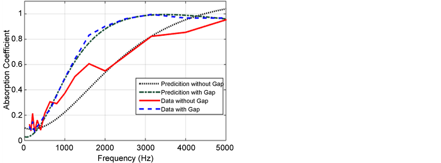
Measurements have been carried out in an impedance tube (SWR) to determine the absorption coefficient of a 10 mm thick material. The material density is calculated to be equal to 161.9 kg/m3. Measurements are carried out on the material in a small tube and in a big tube with and without an air gap. The absorption coefficient values below 1000 Hz are determined using big tube which has an internal diameter of 100 mm, while the results above 1000 Hz are determined using small tube of 30 mm diameter. Absorption coefficient of the material with and without air gap versus frequency are compared with predictions obtained using the laws of Delany and Bazely as seen in Figure 6. Using an air gap of 10 mm behind the material increases the mid and higher frequency performance of the material, while it decreases the lower frequency performance slightly. There is a perfect agreement between data and predictions with air gap while there are slight inconsistencies at lower and higher frequencies between data and predictions without air gap.
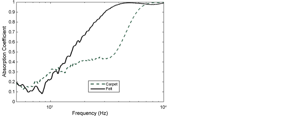
The absorption coefficient obtained using impedance tube method is different than the one obtained using impedance gun, especially at frequencies below 1000 Hz. Two materials, nonwoven (felt) and woven (handmade carpet), have been tested using impedance gun. Materials were backed by rigid impervious wall. Absorption coefficient of felt is higher than the absorption coefficient of carpet for higher frequencies, 1250 - 7000 Hz. But it has a lower absorption coefficient at lower frequency, below 1250 Hz as shown in Figure 7. A sharp drop in absorption coefficient is observed between 500 Hz and 1000 Hz. This might be due to the limitation of lower cut-off frequency of the impedance gun method. Another reason may be low flow resistivity causing a low absorption performance at lower frequency.
Impedance of the material is measured as the complex ratio of sound pressure to particle velocity. The magnitude of the impedance of the material determined
Figure 6. A comparison of predicted and measured absorption coefficient of the felt with and without air gap versus frequency.
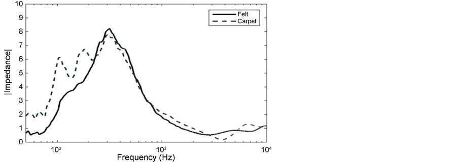
using impedance gun is presented in Figure 8. Resonance peaks have been observed at 300 Hz for carpet and at 340 Hz for felt. The impedance of carpet is higher than the impedance of felt at frequencies below 220 Hz while both impedances are in a good agreement at frequencies above 220 Hz.
4.2. Insertion Loss (IL)
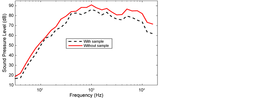
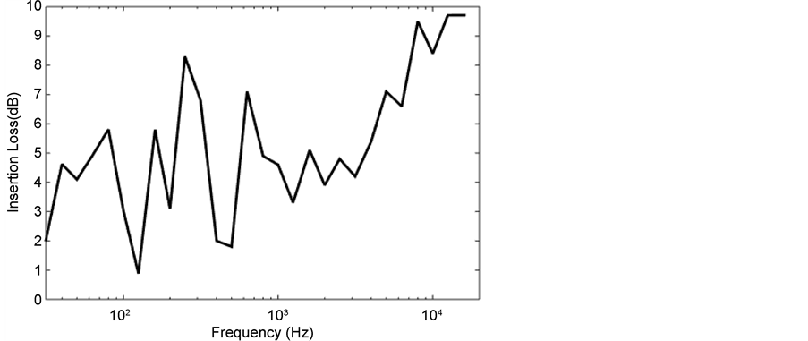
Insertion Loss measurement has been performed on nonwoven material in circular duct. Firstly background sound pressure level in the duct was measured and they were logarithmically subtracted from sound pressure levels measured in presence of noise at the axial centre of the duct. Secondly, a felt material was inserted vertically into transmission path and mounted at the middle of the duct. Edges of the felt was sealed using white silicon to prevent sound propagation through edges of the felt. Then sound pressure levels were measured in presence of noise. Measured sound pressure levels in frequency domain with and without felt are compared in Figure 9. Maximum sound pressure level is obtained at 1000 Hz with and without the sample. Sound pressure levels are reduced using a
Figure 7. Comparison of absorption coefficients of the carpet and felt determined using impedance gun.
Figure 8. The magnitude of the impedance of the material versus frequency.
felt throughout the 1/3 octave frequency band. Insertion loss of felt material is between 1 dB and 10 dB as shown in Figure 10. Better insertion loss is obtained at higher frequencies.
5. Conclusion
Acoustical performance of nonwoven and woven material used for heat insulation and sound absorption was investigated. The porosity of nonwoven is measured using water saturation method and is found to be equal to 0.847. The absorption performance of felt is very similar to the other type of material made of wool. Felt has a lower absorption coefficient at lower frequency and higher absorption coefficient at mid and higher frequencies. Handmade carpet (woven material) has a low absorption coefficient at low- and mid-frequencies while it has a higher absorption coefficient at higher frequency. The absorption coefficient of handmade wool carpet is observed to be lower than the ones of felt at frequencies higher than 1250 Hz. Absorption of felt obtained using standing wave tube with and without air gap behind the materials is in good agreement
Figure 9. Sound pressure level versus 1/3 octave band frequency in the absence and presence of the sample.
Figure 10. Insertion Loss of the felt versus 1/3 octave band frequency.
with predictions determined using the laws of Delany and Bazely. Insertion loss measurements show that felt can reduce the sound pressure level between 1 dB and 10 dB.
Acknowledgements
This work was supported in part by Southampton Solent University and Solent Acoustics.
Cite this paper
Aygün, H. (2017) Characterization of Acoustical Properties of Felt and Carpet Made of Natural and Environmentally Friendly Materials. Open Jour- nal of Acoustics, 7, 27-38. https://doi.org/10.4236/oja.2017.72004
References
- 1. Sardar, J. (2008) A Brief Review on Sound Absorption Characteristics of Non-Woven Structures. Indian Institute of Technology Delhi Press.
- 2. Barber, E.J.W. (1991) Prehistoric Textiles: The Development of Cloth in the Neolithic and Bronze Ages, with Special Reference to the Aegean. Princeton University Press, Princeton.
- 3. Bender, L. (1992) North European Textiles until AD 1000. Aarchus University Press, Aarchus.
- 4. Zwikker, C. and Kosten, C.W. (1949) Sound Absorbing Materials. Elsevier, New York.
- 5. Biot, M.A. (1956) Theory of Propagation of Elastic Wave in a Fluid-Saturated Porous Solid. I. Low-Frequency Range. Journal of the Acoustical Society of America, 28, 168-178.
https://doi.org/10.1121/1.1908239 - 6. Biot, M.A. (1962) Mechanics of Deformation and Acoustic Propagation in Porous Media. Journal of Applied Physics, 33, 1482-1498.
https://doi.org/10.1063/1.1728759 - 7. Delany, M.E. and Bazley, E.N. (1970) Acoustical Properties of Fibrous Absorbent Materials. Applied Acoustics, 3, 105-116.
https://doi.org/10.1016/0003-682X(70)90031-9 - 8. Attenborough, K. (1982) Acoustical Characteristics of Porous Materials. Physics Reports, 82, 179-227.
https://doi.org/10.1016/0370-1573(82)90131-4 - 9. Swift, M.J., Horoshenkov, K.V., Leclaire, P. and Hothersall, D.C. (2000) On the Effect of the Bending Vibration on the Acoustic Properties of Thin Poroelastic Plates. Journal of the Acoustical Society of America, 107, 1786-1789.
https://doi.org/10.1121/1.428577 - 10. Aygün, H. and Attenborough, K. (2008) Sound Absorption by Clamped Poroelastic Plates. Journal of the Acoustical Society of America, 124, 1550-1556.
https://doi.org/10.1121/1.2951586 - 11. Huang, L. (1999) A Theoretical Study of Duct Noise Control by Flexible Panels. Journal of the Acoustical Society of America, 106, 1801-1809.
https://doi.org/10.1121/1.427930 - 12. Huang, L. (2000) Experimental Study of Sound Propagation in a Flexible Duct. Journal of the Acoustical Society of America, 108, 624-631.
https://doi.org/10.1121/1.429594 - 13. Ramamoorthy, S., Grosh, K. and Nawar, T.G. (2003) Structural Acoustic Silencers—Design and Experiment. Journal of the Acoustical Society of America, 114, 2812-2824.
https://doi.org/10.1121/1.1616926 - 14. Munjal, M.L. (1987) Acoustics of Ducts and Mufflers. Wiley, New York.
- 15. Tang, W.C. and Lin, W.Z. (2003) Stiff Light Composite Panels for Duct Noise Reduction. Applied Acoustics, 64, 511-524.
https://doi.org/10.1016/S0003-682X(02)00109-3 - 16. Astley, R.J., Cummings, A. and Sormaz, N. (1991) A Finite Element Scheme for Acoustic Propagation in Flexible-Walled Ducts with Bulk-Reacting Liners, and Comparison with Experiment. Journal of Sound and Vibration, 150, 119-138.
https://doi.org/10.1016/0022-460X(91)90406-A - 17. Cummings, A. and Chang, I.J. (1988) Sound Attenuation of a Finite Length Dissipative Flow Duct Silencer with Internal Mean Flow in the Absorbent. Journal of Sound and Vibration, 127, 1-17.
https://doi.org/10.1016/0022-460X(88)90347-1 - 18. Aygün, H. and Attenborough, K. (2008) The Insertion Loss of Perforated Porous Plates in a Duct without and with Mean Air Flow. Applied Acoustics, 69, 506-513.
https://doi.org/10.1016/j.apacoust.2006.12.007 - 19. Aygün, H. (2006) The Design of Noise Attenuating Devices Incorporating Elastic Porous Structures. Ph.D. Thesis, University of Hull, Kingston upon Hull.
- 20. BS EN ISO 10534-1 (2001) Acoustics. Determination of Sound Absorption Coefficient and Impedance in Impedances Tubes. Method Using Standing Wave Ratio.
- 21. Microflown Tech.
http://www.microflown.com - 22. International Standard ISO 7235 (1991) Acoustics-Measurement Procedures for Ducted Silencers—Insertion Loss, Flow Noise and Total Pressure Loss.
- 23. Beranek, L.L. and Ver, I.L. (1992) Noise and Vibration Control Engineering: Principles and Applications. Wiley Inter-Science, Hoboken.
- 24. Allard, J.F. and Atalla, N. (2009) Propagation of Sound in Porous Media: Modelling Sound Absorbing Materials. 2nd Edition, Wiley-Blackwell, Hoboken.


