

Journal of Electronics Cooling and Thermal Control
Vol.05 No.03(2015), Article ID:59619,20 pages
10.4236/jectc.2015.53004
Modelling and Theoretical Analysis of Laminar Flow and Heat Transfer in Various Protruding-Edged Plate Systems
Abdul Rahim A. Khaled
Mechanical Engineering Department, King Abdulaziz University, Jeddah, Saudi Arabia
Email: akhaled@kau.edu.sa
Copyright © 2015 by author and Scientific Research Publishing Inc.
This work is licensed under the Creative Commons Attribution International License (CC BY).
http://creativecommons.org/licenses/by/4.0/



Received 21 May 2015; accepted 13 September 2015; published 16 September 2015
ABSTRACT
Laminar flow and heat transfer in different protruding-edged plate systems are modelled and analyzed in the present work. These include the Parallel Flow (PF) and the Counter Flow (CF) protruding-edgedplate exchangers as well as those systems being subjected to Constant Wall Temperature (CWT) and Uniform Heat Flux (UHF) conditions. These systems are subjected to normal free stream having both power-law velocity profile and same average velocity. The continuity, mo- mentum and energy equations are transformed to either similarity or nonsimilar equations and then solved by using well validated finite difference methods. Accurate correlations for various flow and heat transfer parameters are obtained. It is found that there are specific power-law indices that maximize the heat transfer in both PF and CF systems. The maximum reported enhancement ratios are 1.075 and 1.109 for the PF and CF systems, respectively, at Pr = 100. These ratios are 1.076 and 1.023 for CWT and UHF conditions, respectively, at Pr = 128. Per same friction force, the CF system is preferable over the PF system only when the power-law indices are smaller than zero. Finally, this work demonstrates that by appropriately distributing the free stream velocity, the heat transfer from a plate can be increased up to 10% fold.
Keywords:
Heat Transfer, Protrusion, (Non-)Similarity Solution, Stagnation Flow, Nonuniform Free Stream, Regression

1. Introduction
Conversion and utilization of energy often involve heat transfer process. This process is encountered in many engineering applications. These applications include steam generation and condensation in power plants; sensible heating and cooling of viscous fluids as in thermal processing of pharmaceutical, agricultural and hygiene products; evaporation and condensation of refrigerants in refrigeration and air-conditioning systems; cooling of engine and turbomachinery systems; and cooling of electrical appliances and electronic devices. It is well known that improving heat transfer over that in the typical practice results in significant increases in both the thermal efficiency and the economics of the plant operation. Improving heat transfer is a terminology that is frequently referred to it in the literature as heat transfer enhancement or augmentation [1] .
Heat transfer enhancement mechanisms basically reduce the thermal resistance in a conventional thermal system by promoting higher convective heat transfer coefficient that can be accompanied with surface area increase. Consequently, the size of a thermal system can be reduced, or the heat duty of an existing thermal system can be increased, or the pumping power requirements can be reduced [1] - [4] . These enhancement mechanisms are classified into passive and active methods [3] . Of special interest to this work is the passive enhancement method. These methods are primarily comprised of at least one of the following mechanisms: (a) increasing the surface area [5] ; (b) interrupting the boundary layer to promote the convective heat transfer coefficient [6] ; (c) using of liquid-vapor phase change [7] ; (d) using the surface coatings to increase velocity near boundaries [8] [9] ; (e) using the liquid and gas additives to enhance thermophysical properties [6] [10] ; (f) using the flow rate and velocity amplification devices [11] [12] ; and (g) layering the immiscible flows [13] - [15] . In the present work, it is interested to investigate heat transfer enhancement due to properly distributing a given flow rate before striking a plate having a protruding edge. This protruding edge is physically important to ensure one-directional stagnation flow along the plate so that heat transfer is maximized.
When a normal free stream strikes a plate having a protruding edge at its inlet, stagnation flow occurs along the plate length which has its stagnation line coinciding with the plate inlet edge. This flow is characterized by having an increasing axial velocity in the vicinity of the plate from zero at the inlet to maximum at the exit [16] -[18] . In addition, it is characterized by having decreasing normal velocity from maximum at the free stream to zero at the plate. Allowing for most of the normal free stream flow rate to be near the inlet causes increases in both axial and normal velocities closing to the plate inlet which promote the average convective heat transfer coefficient. On the other hand, the heat transfer rate is expected to decrease when most of the normal free stream flow rate is considered to be near the plate exit. It is because the latter effect results significantly suppressing the local convective heat transfer coefficients in the upstream region while slightly promoting these coefficients downstream. It is therefore expected that there may be a specific normal free stream velocity profile that can maximize the heat transfer rate from a plate having a protruding edge at its inlet. To the author best knowledge, this proposal has not been investigated in the literature and accordingly it is considered as the motivation behind the present work.
In the next section, the geometries of various analyzed systems composed of plates with protruding edges are explained. These systems include the Parallel Flow (PF) and the Counter Flow (CF) protruding-edged plate exchangers. These systems are exposed to normal free stream having both power-law velocity profile and same average velocity. The continuity, axial momentum and energy equations of the fluids adjacent to the plate are transformed to either similarity and nonsimilarity equations. Also, various similarity equations are obtained for protruding-edged plates subjected to either constant wall temperature or uniform heat flux conditions. The governing equations are solved numerically and are validated against well-established special cases. Different accurate correlations for flow and heat transfer parameters are obtained. An extensive parametric study has been conducted in order explore the influence of power-law index, Prandtl numbers and relative Reynolds numbers on Nusselt numbers and different heat transfer enhancement indicators.
2. Problem Formulation
The proposed two types of protruding-edged plate heat exchangers are shown in Figure 1. These are the Parallel Flow (PF) protruding-edged plate exchanger which is shown in Figure 1(a) and Figure 1(c) and the Counter Flow (CF) protruding-edged plate exchanger which is shown in Figure 1(b) and Figure 1(d). The PF system is formed from T-edged plate while the CF system is composed of Z-edged plate. In both PF and CF systems, the hot and cold fluids approach normally to the separating plate but from different faces. Consequently, hot and cold stagnation fluid flows are induced. These induced flows are forced to flow parallel to each other along the plate length in the PF system as shown in Figure 1(a) and Figure 1(c). The side protrusions within the PF system

 (a) (c)
 (b) (d)
Figure 1. Schematic 2D diagram of the problem and the coordinates system for (a) Parallel Flow (PF) protruding-edged plate exchanger and (b) Counter Flow (CF) protruding-edged plate exchanger, and 3D isometric diagram for (c) PF and (d) CF systems.
are at the plate entrances and they ban fluid flows in the opposite directions. In the CF system, the plate entrance of one face is opposing the entrance of the other face. Both entrances contain side protrusions so as to force the induced hot and cold fluid stagnation flows to have counter current directions as shown in Figure 1(b) and Figure 1(d).
2.1. Modeling of Laminar Flows in the Fluid Volumes in Vicinity of the Plate
Consider that the normal streams approaching the faces of the protruding-edged plate have the following velocity profile along the face length :
:
 (1)
(1)
where  and
and  are the axial distances of the hot and cold fluids from the plate entrances, respectively, as shown in Figure 1(a) and Figure 1(b).
  and
and  are the average free stream normal velocities of the hot and cold fluids, respectively.
  is the power-law index for both normal streams. The conservation of mass principle requires that the free stream axial velocities for the hot and cold fluids be equal to:
 (2)
(2)
where .
.  and
and  are the displacements between the normal free stream of the hot fluid and the plate and that between the normal free stream of the cold fluid and the plate, respectively. The dimensionless continuity and axial momentum equations of the hot and cold fluids in vicinity of the plate are given by [16] [17] :
 3(a, b)
 4(a, b)
where ,
,  ,
,  ,
,  , and
, and  are given by:
 5(a-g)
 6(a, b)
where  and
and  are the density and dynamic viscosity of the hot fluid, respectively. Those for the clod fluid are
  and
and , respectively. The boundary conditions are given by:
 7(a-d)
 7(e, f)
2.2. The Similarity Equations for the Laminar Flow in Vicinity of the Plate
Define the following independent and dependent variables:
 8(a, b)
 9(a, b)
Equations 4(a), 4(b) are transformed to the given similarity equations when Equations (8) and (9) are used:
 (10)
(10)
 (11)
(11)
The transformed boundary conditions are equal to:
 12(a-d)
 12(e, f)
The average skin friction coefficient denoted by  is equal to:
 (13)
(13)
2.3. The Energy Equation for the PF and CF Systems
If  and
and  are defined as
 14(a, b)
then, the energy equations of the hot and cold fluids are given by (Bejan, 2013):
 15(a, b)
where  and
and  are the far stream hot and cold fluid temperatures, respectively.
  and
and  are the Prandtl number for the hot and cold fluids, respectively. The boundary conditions are given by:
 16(a, b)
 16(c)
16(c)
 16(d)
16(d)
where  for the PF system and
  for the CF system. The heat transfer rate between the hot and cold fluids per unit width denoted by
  can be computed from the following equation:
 (17)
(17)
Define the enhancement ratio  as the ratio of the heat transfer rate to that quantity when
 . when
 , the flow in vicinity of the plate surface becomes no more stagnation flow and it will be an external flow parallel to flat plate. Mathematically,
  is equal to:
 (18)
(18)
2.4. The Similarity Energy Equation for the PF System
Invoking the similarity variables given by Equations (8) and (9), Equations (15) and (16) for the PF system reduce to the following similarity equations and boundary conditions:
 (19)
(19)
 (20)
(20)
 21(a, b)
 21(c)
21(c)
 21(d)
21(d)
The dimensionless heat transfer rate per unit width denoted by  is equal to the following for this case:
 (22)
(22)
2.5. The Nonsimilarity Energy Equation for CF System
Invoking the following nonsimilarity variables:
 23(a, b)
to Equations (14) and (15) for the CF system where , the following nonsimilarity equations and boundary conditions are found:
 (24)
(24)
 (25)
(25)
 26(a, b)
 26(c)
26(c)
 26(d)
26(d)
 for this case is equal to:
 (27)
(27)
The average skin friction coefficient  for the PF and CF systems is calculated from the following equation:
 (28)
(28)
2.6. The Similarity Energy Equation for Constant Wall Temperature (CWT) Condition
When , the plate temperature approaches
 . Thus, Equations (19)-(21) reduce to the following:
 (29)
(29)
 30(a, b)
For this case, the local Nusselt number is defined as:
 (31)
(31)
where  is the local convection heat transfer coefficient for the hot fluid flow. The average convective heat transfer coefficient
  given by
  can be computed from the average Nusselt number relation which is equal to:
 (32)
(32)
2.7. The Similarity Energy Equation for Uniform Heat Flux (UHF) Condition
When the plate is generating uniform heat flux  at the surface facing the cold fluid, the dimensionless cold fluid temperature can be redefined as follows:
 (33)
(33)
This is in order to reduce the energy equation given by Equation 15(b) to a similarity equation. This similarity equation is given by:
 (34)
(34)
The boundary conditions for this case are given by:
 35(a, b)
For this case, the local Nusselt number is defined as:
 (36)
(36)
The average Nusselt number relationship is given by:
 (37)
(37)
2.8. The Relation between Heat Transfer in PF and CF Systems and Nusselt Numbers
In terms of average convection heat transfer coefficients, the energy balance given by Equation (17) can be reduced to one equation given by:
 (38)
(38)
The definition of average Nusselt number can be used to show that  is equal to:
 (39)
(39)
3. Numerical Methodology, Validations, Accurate Correlations and Results
3.1. Numerical Methodology
Equation (10) was discretized using three points center differencing after substituting . This resulted in having tri-diagonal system of algebraic equations, which was then solved using the Thomas algorithm [19] . Iterations were implemented in the solution of Equation (10) because the second and third terms on the left of Equation (10) are non-linear. The following linearization models are used to linearize these terms [20] :
 (40)
(40)
 (41)
(41)
where  and
and  are the values of
  and
and  at the previous iteration, respectively. The values of 0.0005 and
  were selected for
  and the convergence criterion for the maximum relative difference in calculating
  between two consecutive iterations. Next, the differential equation
  is solved using the trapezoidal rule [21] . Note that the relationship between
  and
and  is given by:
 (42)
(42)
Also, Equations (19), (20), (29) and (34) were discretized using three points center differencing quotients and the resulted tri-diagonal system of algebraic equations have been solved using the Thomas algorithm without iterations. The left side of Equations 21(d) and 26(d) were discretized using two points difference quotients.
Under assumed plate temperatures, the solutions of the discretized forms of Equations (24) and (25) were obtained using the Thomas algorithm [19] and they were marched from  to
to  using two-points backward difference quotients for the first derivatives in the
  -direction.
  and
and  are located in the numerical mesh at lines
  and
and , respectively, where
  is the total number of discretized points along
  direction.
  is the total number of discretized points along
  direction. The step sizes
  and
and  are taken to be
  and
and , respectively. Then, the plate temperature was modified using the discretized form of Equation 26(d). This discretized equation can be rearranged in the following form:
 (43)
(43)
The marching procedure used for solving Equations (24) and (25) were repeated by letting the assumed plate temperatures  equal to those modified by Equation (43). This process is continued until the maximum relative error between the assumed and modified plate temperatures is less than
 . Note that
  and
and  are the dimensionless cold and hot fluids temperatures at
  and
and , respectively.
3.2. Validations and Numerical Results
When  and
and , the flows become laminar flow parallel to flat plate and stagnation flow with uniform normal free stream velocity, respectively. The solution for these two cases is well documented in literature [17] . The comparisons between the present numerical method solutions and the reported values of the average Nusselt numbers for CWT condition when
  and
and  and the average Nusselt number for UHF condition when
  are shown in Table 1. Excellent agreements between both results are shown in this table. This lead to increased confidence in the results of the present work.
3.3. Accurate Correlations
Correlation for transformed axial velocity and the average skin friction coefficient
 can be shown to be correlated to
  and
and  according to the following correlation:
 (44)
(44)
where
 (45)
(45)
The coefficients  where
where  and
and  are given in Table 2(a) and Table 2(b). These coefficients produce maximum relative error in computing
  less than 0.213% when
  and
and . Also,
  is correlated to
  through the following correlation:
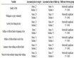
Table 1. Comparisons between the numerical solutions and those presented in Bejan (2013) at Prh = 1.
(a) (b)
Table 2. (a) Coefficients bi,j of the correlation given by Equation (44), i = 1, 2, 3, 4, 5; (b) Coefficients bi,j of the correlation given by Equation (44), i = 6, 7, 8, 9, 10.
 (46)
(46)
Correlation (46) has maximum relative error less than 0.026% when .
.
Correlation for the transformed boundary layer thickness
The edge of the transformed boundary layer  that produce
  can be shown to be correlated to
  according to the following correlation:
 (47)
(47)
Correlation (47) has maximum relative error less than 0.031% when .
.
Correlations for average Nusselt number for CWT and UHF conditions
The average Nusselt number for CWT and UHF conditions can be shown to be correlated to  and
and  according to the following correlations:
 48(a, b)
where
 49(a, b)
The coefficients  where
where  and
and  are given in Table 3(a) and Table 3(b) for the CWT condition and Table 4(a) and Table 4(b) for the UHF condition. These coefficients produce maximum
relative error in computing  less than 0.935% for the CWT condition and less than 0.996% for the UHF
condition when  and
and .
.
(a) (b)
Table 3. (a) Coefficients di,j of the correlation given by Equation 48(a) for CWT condition, i = 1, 2, 3, 4, 5; (b) Coefficients di,j of the correlation given by Equation 48(a) for CWT condition, i = 6, 7.
(a) (b)
Table 4. (a) Coefficients di,j of the correlation given by Equation 48(b) for UHF condition, i = 1, 2, 3, 4, 5; (b) Coefficients di,j of the correlation given by Equation 48(b) for UHF condition, i = 6, 7.
Correlations for maximum average Nusselt numbers and critical power-law indices
The maximum average Nusselt numbers for CWT and UHF conditions can be shown to be correlated to  according to the following correlations:
 50(a, b)
These correlations have maximum relative error of 0.202% and 0.233% for the CWT and UHF conditions, respectively, when . These maximum values are obtained when the power-law index
  is set to be equal to a critical value denoted by
 . This critical value is correlated to the Prandtl number according
to the following correlations:
 51(a, b)
These correlations have maximum relative error of 0.0355% and 0.0309% for the CWT and UHF conditions, respectively, when .
.
Correlations for exit Nusselt number and critical power law index for UHF condition
The maximum Nusselt number at the plate exit for the UHF condition can be shown to be correlated to  according to the following correlation:
 (52)
(52)
This correlation has maximum relative error of 0.583% when . The critical power-law index
  that produces
  is correlated to the
  according to the following correlation:
 (53)
(53)
This correlation has maximum relative error of 0.631% when .
.
4. Discussion of the Results
4.1. Discussion of Flow and Thermal Aspects for CWT and UHF Conditions
In Figure 2, the dimensionless velocity  at the plate exit which is given by
  is noticed to increase as both
  and
and  increase. The subfigure within this figure shows that the average skin friction coefficient has one local maximum of value
  at critical power-law index of
 . The average Nusselt numbers as functions of Prandtl numbers for both CWT and UHF conditions are shown in Figure 3. By analyzing the CWT data of this figure, it can be shown that
  is proportional to
  where the minimum value of
  is
is  when
when  and
and  while the maximum value of
  is
is  when
when  and
and .Also by analyzing the UHF data in Figure 3, it can be seen that
  is proportional to
  where the minimum value of
  is
is  when
when  and
and  while the maximum value of
  is
is  when
when  and
and . Figure 4 shows that there is always local maximum value for the average Nusselt number when
  for both CWT and UHF conditions.
The heat transfer rate per same friction force is proportional to . This quantity is shown from Figure 5 to have local minimum when
  for the CWT condition while it decreases as
  increases for the UHF condition. This means that the flow parallel to flat plate gives more heat transfer rate under UHF condition when the operation requires same friction force. However, stagnation flow with larger non-negative power-law indices gives more heat transfer rate under the CWT condition when the operation requires same friction force. The plots of maximum average Nusselt numbers and critical power-law indices producing these values are shown in Figure 6. Both the maximum average Nusselt numbers and critical power-law indices increase as Prandtl numbers increase however, the increases in the critical power-law indices becomes asymptotically for large Prnadtl numbers. Notice that themaximum average Nusselt numbers for the UHF condition are always larger than those

Figure 2. Effects of m on  and
and .
.

Figure 3. Effects of Prh,c on  for CWT and UHF conditions.

Figure 4. Effects of m on  for CWT and UHF conditions.

Figure 5. Effects of m on  for CWT and UHF conditions.

Figure 6. Effects of Prh,c on  and mcr for CWT and UHF conditions.
corresponding to the CWT condition while it is vice versa for the critical power-law index plots. It is shown in Figure 7 that the local Nusselt number at the plate exit for the UHF condition has local maximum value when  as clearly seen in Figure 8. This means that stagnation flow with power-law index between
  under UHF condition results in coldest plate condition.

Figure 7. Effects of m on NuL for UHF condition.

Figure 8. Effects of Prc on NuL,max and mcr for UHF condition.
4.2. Discussion of Flow and Thermal Aspects for PF and CF Systems
Figure 9 shows that both hot and cold fluid temperatures increase as  increase, respectively, for the PF protruding-edged plate exchanger. For the CF protruding-edged plate exchanger and as shown in Figure 10, the plate temperature is noticed to decrease as
  increases when
 , while it increases as
  increases when
 . When
 , Equations (24) to (26) become similarity equations and physically PF and CF systems have same performance as the boundary layers at this case have fixed thicknesses
  as dictated from Equations (8). It is shown in Figure 11 that the heat transfer rates between the hot and cold fluids for both PF and CF systems are maximized at critical power-law indices laying between
 . The performance of the PF system is well modeled by Equation (39) and the Correlation (48) for the CWT condition as seen in Figure 11 on the plot given by
 . This is because that the PF system has always constant separating plate temperature. The plot indented by
  for the CF system shows that the performance of the CF system can be accurately modeled by Equation (39) and the Correlation (48) for the UHF condition when
 .
.
It is shown in Figure 12 that the maximum heat transfer enhancement ratio is equal to  and
and  for the PF and CF systems, respectively. These values are for
  plots. Also, Figure 12 shows that the CF system has higher enhancement ratios than the PF system when
  is quite below
  while the PF system has higher enhancement ratios than the CF systems when
  is quite above
 . The heat transfer rates per same friction forces that is proportional to
  are seen in Figure 13 to be larger for the PF system than those for the CF system when
  while it is vice versa when
 . Also, this figure shows that
  is maximized for the CF system when
  laying between
  while it is almost increasing linearly as
  increases for the PF system. In Figure 14, the heat transfer enhancement ratio is noticed to increase as Prandtl numbers increase for both PF and CF systems. Using
  for the CWT condition (i.e. obtained from correlation 51(a)) with CF system is noticed to produce larger enhancement ratios than those obtained using
  for the UHF condition (i.e. using Correlation 51(b)). The maximum enhancement ratios shown in Figure 14 are equal to
  and
and  for the PF and CF systems, respectively, with m given by Correlation 51(b) and at
 .
.

Figure 9. Effects of m on temperature profile for PF system.

Figure 10. Effects of m on plate temperature for CF system.

Figure 11. Effects of m on dimensionless heat transfer rate for CF and PF heat exchangers.

Figure 12. Effects of m on heat transfer enhancement ratio for CF and PF systems.

Figure 13. Effects of m on  for CF and PF systems.

Figure 14. Effects of m on heat transfer enhancement ratio for CF and PF systems.
5. Conclusion
Laminar flow and heat transfer in various protruding-edged plate systems are modeled and investigated in the present work. These systems include the Parallel Flow and the Counter Flow protruding-edged plate exchangers as well as those systems being subjected to CWT and UHF conditions. These systems are exposed to normal free stream having both power-law velocity profile and same average velocity. The continuity, axial momentum and energy equations are transformed to similarity equations for CWT and UHF conditions as well as for the Parallel Flow system while they are transformed to non-similarity equations for the Counter Flow system. These equations are solved by using an accurate finite difference method. Excellent agreement is obtained between the numerical results and reported solutions of well-established special cases. Accurate correlations for different flow and heat transfer parameters are generated by using modern regression tools. It is found that there are always local maximum values for Nusselt numbers for both CWT and UHF conditions at specific power-law indices. Also, it is found that there are specific power-law indices that can maximize the heat transfer rate in the Parallel and Counter Flow systems. The maximum enhancement ratios for the Parallel and Counter Flow systems that are identified in this work are 1.075 and 1.109, respectively, which occur at Pr = 100. These ratios are 1.076 and 1.023 for CWT and UHF conditions, respectively, at Pr = 128. Per same friction force, the counter flow system is found to be preferable over the Parallel Flow system only when the power-law indices are smaller than zero. Finally, this work paves a way for new passive heat transfer enhancement method that can enhance heat transfer from a plate by a magnitude of 10% fold which is by appropriately distributing the free stream velocity.
Cite this paper
Abdul Rahim A.Khaled, (2015) Modelling and Theoretical Analysis of Laminar Flow and Heat Transfer in Various Protruding-Edged Plate Systems. Journal of Electronics Cooling and Thermal Control,05,45-65. doi: 10.4236/jectc.2015.53004
References
- 1. Bejan, A. and Kraus, A.D. (2003) Heat Transfer Handbook: Volume 1. John Wiley & Sons, New York.
- 2. Manglik, R.M., Ravigururajan, T.S., Muley, A., Papar, R.A. and Kim, J. (2000) Advances in Enhanced Heat Transfer. ASME, New York.
- 3. Bergles, A.E. (2000) New Frontiers in Enhanced Heat Transfer. In: Manglik, R.M., Ravigururijan, T.S., Muley, A., Papar, A.R. and Kim, J., Eds., Advances in Enhanced Heat Transfer, ASME, New York, 1-8.
- 4. Kakaç, S., Liu, H. and Pramuanjaroenkij, A. (2013) Heat Exchangers Selection, Rating and Thermal Design. 3rd Edition, CRC Press, Boca Raton.
- 5. Kraus, A.D., Aziz, A. and Welty, J. (2002) Extended Surface Heat Transfer. John Wiley & Sons, New York.
- 6. Siddique, M., Khaled, A.R.A., Abdulhafiz, N.I. and Boukhary, A.Y. (2010) Recent Advances in Heat Transfer Enhancements: A Review Report. International Journal of Chemical Engineering, 2010, Article ID: 106461.
http://dx.doi.org/10.1155/2010/106461 - 7. Léal, L., Lavieille, P., Amokrane, M., Pigache, F., Topin, F., Nogarède, B. and Tadrist, L. (2013) An Overview of Heat Transfer Enhancement Methods and New Perspectives: Focus on Active Methods Using Electroactive Materials. International Journal of Heat and Mass Transfer, 61, 505-524.
http://dx.doi.org/10.1016/j.ijheatmasstransfer.2013.01.083 - 8. Connor, O., Patrick, J., You, S.M. and Price, D.C. (1995) A Dielectric Surface Coating Technique to Enhance Boiling Heat Transfer from High Power Microelectronics. IEEE Transactions on Components, Packaging, and Manufacturing Technology, Part A, 18, 656-663. http://dx.doi.org/10.1109/95.465166
- 9. Buffone, C., Sefiane, K. and Buffone, L. (2005) Heat Transfer Enhancement in Heat Pipe Applications Using Surface Coating. Journal of Enhanced Heat Transfer, 12, 21-35.
http://dx.doi.org/10.1615/JEnhHeatTransf.v12.i1.20 - 10. Kakaç, S. and Pramuanjaroenkij, A. (2009) Review of Convective Heat Transfer Enhancement with Nanofluids. International Journal of Heat and Mass Transfer, 52, 3187-3196.
http://dx.doi.org/10.1016/j.ijheatmasstransfer.2009.02.006 - 11. Khaled, A.R.A. and Vafai, K. (2003) Cooling Enhancements inside Thin Films Supported by Flexible Complex Seals in the Presence of Ultrafine Suspensions. Journal of Heat Transfer—Transactions of the ASME, 125, 916-925.
http://dx.doi.org/10.1115/1.1597612 - 12. Khaled, A.R.A. and Vafai, K. (2002) Flow and Heat Transfer inside Thin Films Supported by Soft Seals in the Presence of Internal and External Pressure Pulsations. International Journal of Heat and Mass Transfer, 45, 5107-5115.
http://dx.doi.org/10.1016/S0017-9310(02)00220-X - 13. Khaled, A.R.A. and Vafai, K. (2014) Heat Transfer Enhancement by Layering of Two Immiscible Co-Flows. International Journal of Heat and Mass Transfer, 68, 299-309.
http://dx.doi.org/10.1016/j.ijheatmasstransfer.2013.09.040 - 14. Al Omari, S.A.B. (2011) Enhancement of Heat Transfer from Hot Water by Co-Flowing It with Mercury in a Mini- Channel. International Communications of Heat and Mass Transfer, 38, 1073-1079.
http://dx.doi.org/10.1016/j.icheatmasstransfer.2011.04.026 - 15. Khaled, A.R.A. (2014) Heat Transfer Enhancement in a Vertical Tube Confining Two Immiscible Falling Co-Flows. International Journal of Thermal Sciences, 85, 138-150.
http://dx.doi.org/10.1016/j.ijthermalsci.2014.06.023 - 16. White, F.M. (2006) Viscous Fluid Flow. 3rd Edition, McGraw-Hill, Boston.
- 17. Bejan, A. (2013) Convection Heat Transfer. John Wiley & sons, New York. http://dx.doi.org/10.1002/9781118671627
- 18. Bhattacharyya, K. and Layek, G.C. (2011) Effects of Suction/Blowing on Steady Boundary Layer Stagnation-Point Flow and Heat Transfer towards a Shrinking Sheet with Thermal Radiation. International Journal of Heat and Mass Transfer, 54, 302-307.
http://dx.doi.org/10.1016/j.ijheatmasstransfer.2010.09.043 - 19. Blottner, F.G. (1977) Finite-Difference Methods of Solution of the Boundary-Layer Equations. The American Institute of Aeronautics and Astronautics Journal, 8, 193-205.
http://dx.doi.org/10.2514/3.5642 - 20. Arpaci, V.S. and Larsen, P.S. (1984) Convection Heat Transfer. Prentice Hall, New York.
- 21. Atkinson, K.E. (1989) An Introduction to Numerical Analysis. 2nd Edition, John Wiley & Sons, New York.
Nomenclature
Greek Symbols
Subscripts