Journal of Electronics Cooling and Thermal Control
Vol.2 No.1(2012), Article ID:18352,16 pages DOI:10.4236/jectc.2012.21001
Experimental Study of Heat Transfer to Flowing Air inside a Circular Tube with Longitudinal Continuous and Interrupted Fins
Department of Mechanical Power Engineering, Zagazig University, El-Sharkia, Egypt
Email: *shamad53@hotmail.com
Received January 23, 2012; revised February 21, 2012; accepted February 28, 2012
Keywords: Internal Flow; Turbulent Flow; Heat Transfer; Interrupted and Continuous Fins; Fin Analysis
ABSTRACT
Experimental investigations have been performed to determine the detailed module-by-module pressure drop and heat transfer coefficient of turbulent flow inside a circular finned tube. The tubes are provided with longitudinal fins continuous or interrupted in the stream wise direction by arranging them both in a staggered and in-line manner. Experiments are carried out for two different fin geometries, with two numbers of fins (N = 6 and 12). All tested finned tubes have 16 modules each with length equal to the tube diameter (L = D = 30 mm). The thermal boundary condition considered here, is a uniform heat flux. The module-by-module heat transfer coefficient is found to vary only in the first modules, and then attained a constant thermally periodic fully developed value after eight to twelve modules. The results also showed that in the periodic hydrodynamic fully developed region, the value of the pressure drop along the tube with continuous fins is greater than that of the in-line arrangement, and lower than that of the staggered arrangement. Furthermore, the results showed that in the periodic fully developed region, the tube with continuous fins produces a greater value of the heat transfer coefficients than that the tube with interrupted fins, especially through a high range of Reynolds number (5 × 10⁴ > Re > 2 × 10⁴). The tube with Staggered arrangement of fins produces a greater value of the heat transfer coefficient than the tube with continuous fins and the in-line arrangement finned tube at low Reynolds number (Re < 1.2 × 10⁴).). It was found that the fins efficiency is greater than 90 percent; in the worst case (maximum Reynolds number with continuous fins tube).
1. Introduction
The demand for high-performance heat exchange devices having small spatial dimensions is increasing due to their need in applications such as aerospace and automobile vehicles, cooling of electronic equipment, and so on. This has led to various designs of a compact heat exchanger. Internal fins are the most commonly used technique for enhancing the rate of heat transfer between the surface and a flowing fluid. It has been recognized for some time that higher heat transfer rates can be obtained when the internal fin surfaces of circular tubes are periodically interrupted in the stream wise direction, resemble the offset-fin heat exchanger. Heat transfer enhancement is accompanied by an increase in a pressure drop due to the increase of the friction factor. Since the friction power, expenditure is equally very important for the exchanger surfaces, it is therefore, of interest, to study the heat-transfer performance of an internally finned circular tube with fin surface interrupted in the stream wise direction.
Numerical predictions of the laminar fluid flow and the forced convection heat transfer in the entrance region of internal longitudinal finned tubes have been investigated by various researchers. Rustum and Soliman [1] as well as Campo and Morales [2] conducted numerical studies based on standard finite differences for the thermal development of a fluid flow through tubes with fully developed hydrodynamics. Prakash and Liu [3] and Choudhary and Patankar [4] have been independently examined, the problem of simultaneously developing flow and heat transfer in a tube. They used a modified control volume technique for solving the governing conservation equations numerically. Hu and Chang [5] studied theoretically the case of fully developed velocity and temperature simultaneously of an internally continuous finned tube at constant heat flux. Masliyah and Nandakumar [6] considered the fins of a triangular shape with finite thickness. Soliman et al. [7] have been investigated the laminar heat transfer in an internally finned tube with uniform outside wall temperature. Patankar et al. [8] used a mixing length model to predict numerically the fully developed turbulent flow and heat transfer characteristics of circular tubes and annuli equipped with longitudinal internal fins. Kim and Webb [9] developed an analytical treatment for the friction factor and heat transfer coefficient in rectangular and circular channels with internal continuous longitudinal fins. Sparrow et al. [10] have been presented a numerical investigation of fluid flow and heat transfer in a two-dimensional staggered offsetfin array. Sparrow and Liu [11] have been made a performance comparison for two dimensional in-line and staggered fin arrays.
London and Shah [12] as well as Joshi and Webb [13] have been investigated experimentally offset-fin arrays. Patakar and Prakash [14] have been studied numerically the effect of plate thickness on heat transfer of two-dimensional staggered fin arrays. Kelkar and Patankar [15] have been analyzed a three-dimensional flow and a heat transfer in offset-fin arrays. Analytical models to predict laminar and turbulent flow and heat transfer offset-been arrays have been investigated by Joshi and Webb [16]. Kelkar and Patankar [17] investigated the performance of an internal longitudinal finned circular tube with fin surface interrupted in the stream wise direction by arranging them both in the staggered and in-line manner for laminar flow.
Xiaoyue and Michael [18] presented a parametric study on a turbulent and heat transfer in internally finned tubes. Three fin profiles-rectangle, triangle, and round crest-with the same fin heights, widths, and helix angles were compared. Saha and Langille [19] studied heat transfer and pressure drop characteristics in a circular tube fitted with full-length strip, short-length strip, and regularly spaced strip elements. Zeiton and Hegazy [20] presented an analysis study for a fully developed laminar convective heat transfer in a pipe provided with internal longitudinal fins, and with uniform outside wall temperature. The fins are arranged in two groups of different heights. The numerical results showed that the height of the fin effects greatly flow and heat transfer characteristics.
The present work is carried out experimentally to study a heat transfer for turbulent flow inside circular tubes equipped with internal longitudinal interrupted (staggered and in-line) fins. The plain tube and the tube with continuous fins are also investigated mainly for comparison with the interrupted finned tubes. Two main geometries: 1) (N = 6, with  = 0.5), and 2) (N = 12, with
  = 0.3) have been used in this study. The simultaneous development of velocity and temperature fields are considered, when the fluid enters the tested finned tubes with uniform inlet velocity and uniform temperature. The thermal boundary condition is being a uniform heat input per unit area (constant surface heat flux). The radial and axial heat conduction through the tube wall is neglected. Air is the working fluid in all experiments with assuming constant properties. The Reynolds number range extends from 5 × 10³ to 5 × 10⁴ based on the hydraulic diameter of the tested finned tubes.
2. Experimental Apparatus and Procedure
The main objective of the present experimental work was defined, that is to determine the detailed module-bymodule pressure drop and heat transfer coefficient of the turbulent flow inside circular tubes with internal longitudinal fins that are continuous and interrupted. The interrupted fins are arranged in a staggered and an in-line manner. The apparatus consists mainly of air passage, heating unit, and measuring instruments, as shown in Figure 1. Air is sucked from the laboratory atmosphere and blows into the tested tube. A motor-driven fan, running at a constant speeds, draws air through a control valve (gate valve), and delivers it into a U-shaped tube of 75 mm internal diameter to the tested tube through a conical nozzle. The conical convergent nozzle gives nearly a uniform velocity distribution at the inlet of the tested tube. A British standard orifice plate of 40 mm diameter was installed in the apparatus to measure the air flow rate. It was calibrated by integrating the velocity profile in a fully developed region of a plain circular tube with 32.6 mm diameter.
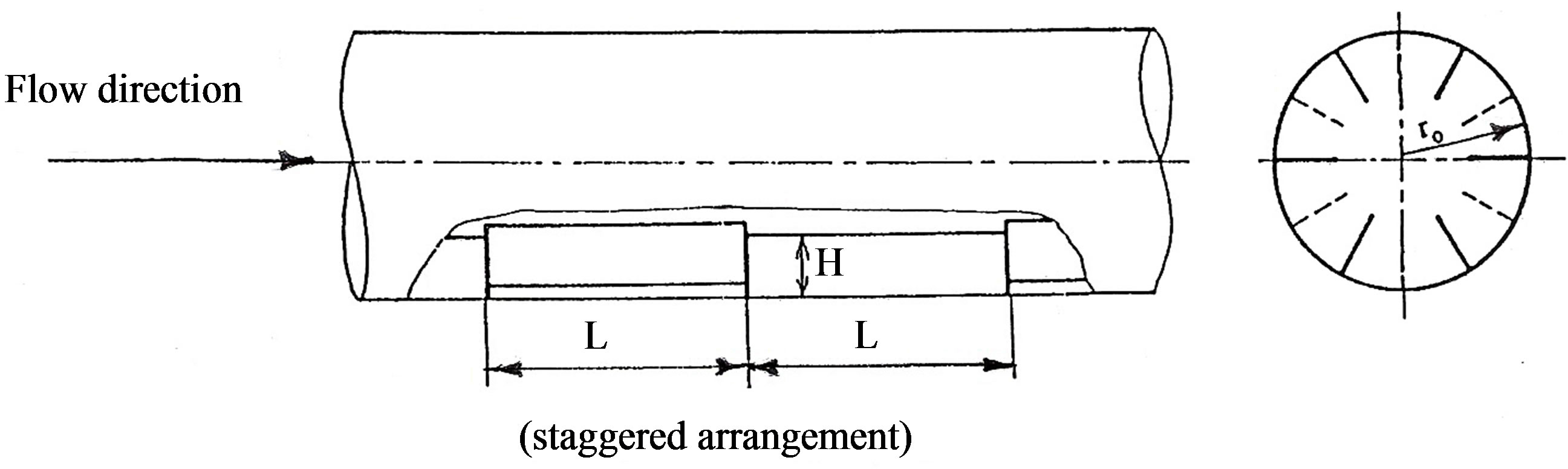
The tested tubes were made of a brass plain tube (outer diameter = 31.8 mm, and inner diameter = 30.25 mm) in which axial slots were machined on its surfaces to insert 0.6 mm thick fins made also of brass strips. The plain tubes slots were made continuously and interrupted by using 0.6 mm thick cutter on a milling machine. The strips were sheared by CNC shearing machine. Special cores were used for fins insertion to ensure that 1) all fins inside the tube have the same height, and 2) all the recognized extensions of the fins passing through the centerline (see Figure 2). All tested tubes with interrupted fins have 16 modules, each of length equal to a tube diameter (≈30 mm). The continuous fins tube has fins of a length equal to 36 times a tube diameter. All tested tubes with interrupted fins have a distance equal to two and three tube diameter length free of fins at the tube entrance and exit respectively. On the other side, the tube with continuous fins has a distance equal to one and four tube diameter length free of fins at the tube entrance and exit respectively.
Axial pressure distribution was measured with aid of 9 static taps (0.5 mm inner diameter) for the interrupted finned tubes, and 37 static taps for the continuous fins
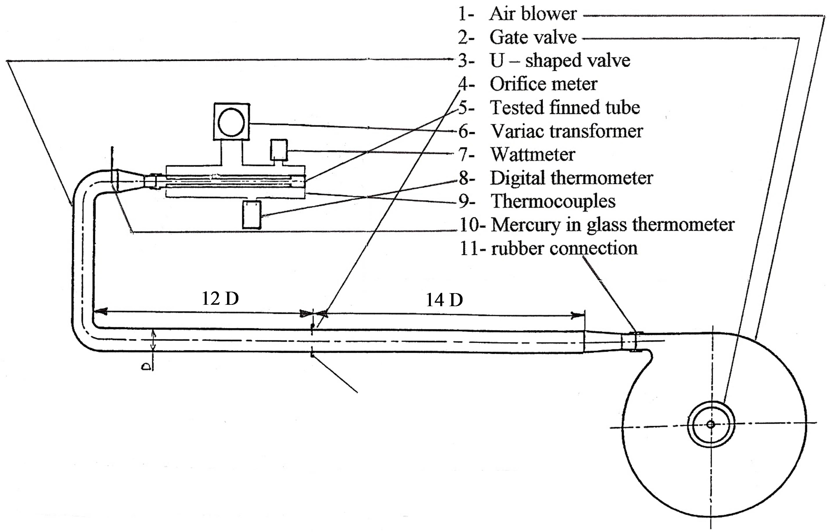
Figure 1. Schematic diagram of experimental apparatus.
 (a)
(a)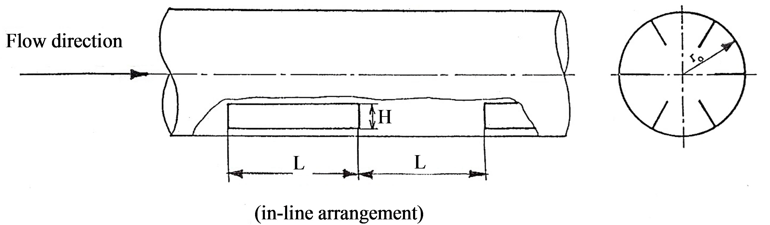 (b)
(b)
Figure 2. (a) Fins insertion in the tube and core; (b) Schematic of different geometries in this study.
tube distributed along the tube outer surface. Taps were installed along the line lies in the middle between two fins. The pressure signals from the taps are conveyed to the pressure selector switch via plastic tubes. The output signals of the pressure selector switch are sensed by a micro manometer with accuracy ± 0.01 mm of H2O.
3. Heating Units and temperature Aspects
The tested finned tube was heated by an Ohmic dissipation in an electric resistance tape (2 mm width, and 0.2 mm thickness). The tape heater power of 1900 Watts at 265 Volt, and 7.3 Ampere, was wound uniformly on the outer surface of the tube. The power of the heater was controlled by a variac transformer, which provides a controllable constant heat flux along the surface of the tested tubes. The electric power input to the heater was measured by an in-line digital wattmeter (accuracy ± 0.5%). Over the range of test conditions; the output-input air temperature difference was kept constant at approximately 32˚C. A 1.5 mm thick layer of asbestos insulated the outer surfaces of the tested finned tubes electrically. The outer surface of the heater was insulated thermally by a 35 mm thick glass wool (k = 0.041 W/m·k). The insulation layer and the heater tape covered all the outer surface of the tested tube except a two diameter length from the tube entrance. Copper-constantan calibrated thermocouples of 0.4 mm diameters were embedded at 0.5 mm depth from the outer surface of the tested finned tube to measure the local surface temperatures. Three thermocouples, distributed circumferentially, were used for each module at one traverse cross-sectional area. They were at the exit of the finned module as well as a distance equal to 60 percent of the un-finned module length as shown in Figure 3. Eighteen thermocouples at a six traverse cross-sectional areas (distributed uniformly and axially) for a one finned module in the periodic fully developed region were used to determine the local heat transfer coefficient of the module. Eighteen thermocouples were also distributed along the un-finned successive module of the in-line arrangements. Six of them are used to give the local fin base temperatures. The details of all thermocouples positions for both arrangements are shown in Figure 4. Six thermocouples were uniformly distrib-
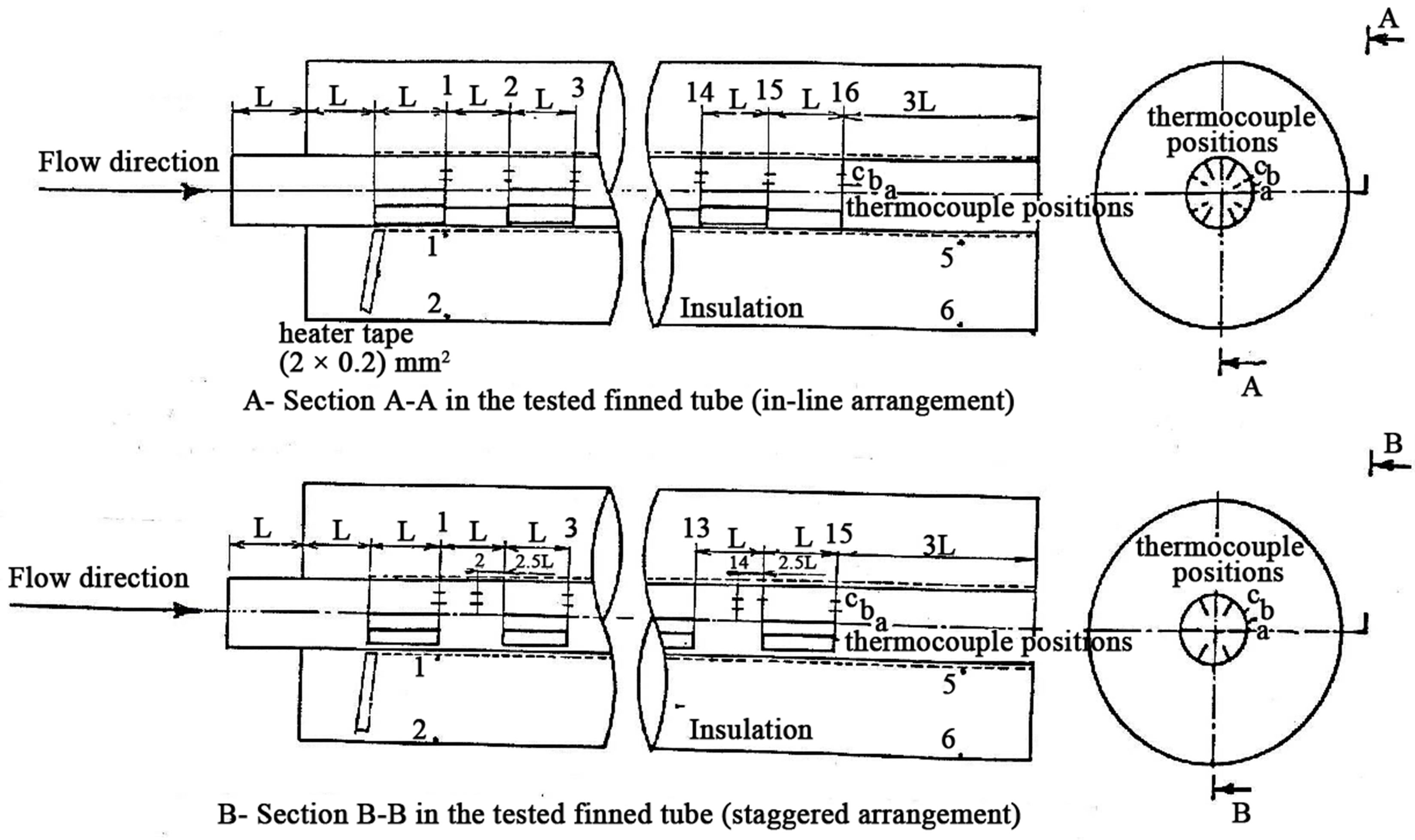
Figure 3. Schematic locations of the thermocouples junctions on the surface of the tested finned tubes.
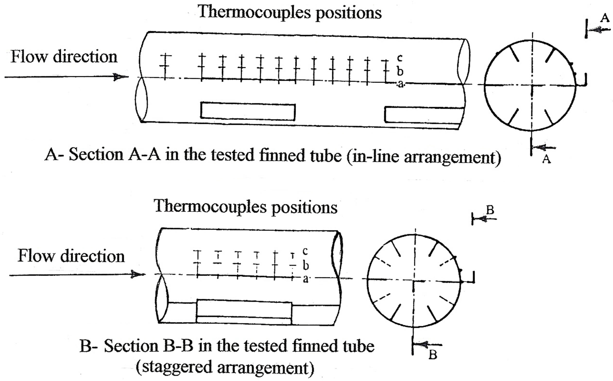
Figure 4. Schematic locations of the thermocouples junctions along the module for in-line and staggered arrangements.
uted along the inner and the outer surfaces of the insulation (glass wool) to determine the radial conduction losses. The reading of the thermocouples was taken out by a digital thermometer of accuracy ± 0.4˚C. A standard mercury thermometer was used to read the inlet temperature of the flowing air stream. Another five thermocouples were distributed at the tested finned tube exit to read the outlet temperature of the flowing air stream.
The total rate of heat generated from the heater (qt) was distributed into the heat transferred by convection to the flowing air (qc), and heat losses to the outside of the tested tubes. The heat transferred by convection to the air stream is given by:
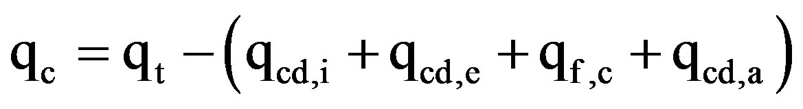 (1)
(1)
where:
qt = The total input power to the heater, W qcd,i = The heat lost by conduction through the insulation in the axial and radial directions, and it is given by:
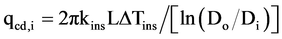 (2)
(2)
where:
kins = The thermal conductivity of the insulation, W/m·K.
L = The length of the insulated section of tube, m.
Di = Inner diameter of the insulation, m.
Do = Outer diameter of the insulation, m.
ΔTins = The average temperature difference between the inner and the outer surfaces of the insulation and it is given by:
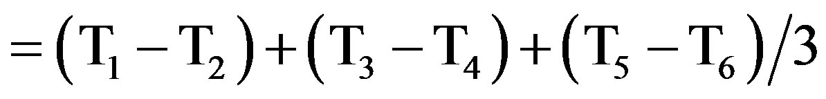 , K.
, K.
It was found that it represents about 7.6% of the total heat input for the maximum case at minimum Reynolds number.
qcd,e = The heat lost by conduction through the tube wall in the insulated entrance region retarded the flow. It is given by:
 (3)
(3)
where:
AW = The cross-sectional area of the tube wall, m2.
ΔTw = The wall temperature difference per one module length in the entrance region without heating, K.
Δx = The module length in the entrance region without heating, m.
k = The thermal conductivity of the tube material, W/m·K.
It was found that it represents about 0.03% of the total heat input for the maximum case at minimum Reynolds number.
qf,c = The heat lost by free convection from the rear face of the tested finned tube (W). It is given by:
 (4)
(4)
where:
hf = The heat transfer coefficient by free convection, W/m2·K.
Tr,f = The rear face surface temperature, K.
Ta = The surrounding air temperature, K.
It was found that it does not exceed 0.018 percent of the total heat input.
qcd,a is the heat lost by axial conduction through the tested finned tube wall. In our study, the Peclet number (Pe = Re·Pr) was typically greater than 1000. Therefore, the axial heat conduction loss through convection air is neglected as noted in [21].
Except qcd,i, the other heat losses can be neglected due to their small values as compared with the total heat input value.
The investigated parametric variations are: fins number (N), relative fin height ( ), and the arrangement manner. The arrangement may be classified into two geometries as shown in Table 1.
For a certain required rate of air discharge of air in the tested tube, the pressure difference across the orifice meter was determined. The gate valve opining was adjusted to giving that pressure difference. Throughout the experiment, this pressure difference was kept constant. The flow was characterized by Reynolds number based on hydraulic diameter (Reh), and on a velocity via the minimum cross-sectional area of the tested finned tube. The range of the hydraulic Reynolds number based on the plain tube diameter (Re) was 104 to 105 approximately. For each tested tube, groups of experiments were performed to determine the heat transfer coefficient per module. Both the velocity and the temperature distributions at two diameter lengths from the tube entrance were determined to check the uniformity of both the velocity and the temperature profiles.
4. Method of Calculation
The essential quantities, which were determined in this study, include the mass flow rate of air ( ), wall temperatures, and electric power input to the heater. The air mass flow rate was calculated from the measured values of pressure difference across the standard orifice plate (Cd = 0.64 ± 0.005), and the density of the flowing air
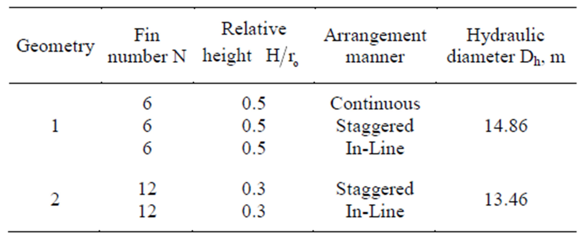
Table 1. Arrangements of fins inside the tested tubes.
according to its inlet temperature.
The bulk velocity can also be calculated from the continuity equation as:
 (5)
(5)
and
 (6)
(6)
For internal flow, the equivalent hydraulic diameter Dh is often used as the characteristic length. It is defined as
 (7)
(7)
The hydraulic Reynolds number Reh based on the Dh is defined as:
 (8)
(8)
Using the plain tube diameter, D, as the characteristic length, the Reynolds number based on it is defined as:
 (9)
(9)
The module-averaged friction factor based on the hydraulic diameter (fh) can be defined as
 (10)
(10)
while the module-averaged friction factor based on the plain tube diameter is defined as
 (11)
(11)
where Δp = The total pressure drop across a module length (2L).
The performance of the tested finned tubes is compared with the Blasius formula of the plain tube [22]
 (12)
(12)
also, the pressure distribution along the tested finned tubes is considered in the dimensionless form as
 (13)
(13)
where:
P = The dimensionless pressure drop.
Pi = The pressure at the tube entrance, N/m2.
Px = The pressure at an axial station x, N/m2.
The pressure is measured at a distance equal to the module length, starting from the entrance of the first module.
The Nusselt number was calculated from the measured values of the wall temperatures. The wall temperatures were also measured at the modules exit as well as at a distance equal to 0.6 L of the un-finned modules, as shown in Figure 4. At these positions, it was found that the value of the local Nusselt numbers is nearly equal to the value of the module averaged Nusselt numbers, along the modules. The module averaged Nusselt number can be obtained from the integration of the local Nusselt number along the module. Then, the module-averaged Nusselt number based on the hydraulic diameter can be defined as:
 (14)
(14)
where (ht,a) is the convective heat transfer coefficient based on the total heat transfer area (plain and finned area), and it is calculated as
 (15)
(15)
where:
ka = The thermal conductivity of the air. It is taken at the average temperature of the air stream .
.
qm = The rate of heat transfer per unit area for one module, W.
P = , the wetted perimeter, m.
It is a common practice in applications involving fins to de-rate the fin surface area by efficiency η [23] as we can see in the wetted perimeter equation.
Based on the diameter of the plain tube (D as the characteristics length), then the Nusselt number (Nu) can be given by:
 (16)
(16)
where (h) can be calculated from the following equation as
 (17)
(17)
where:
Tw = The wall temperature of the module which is determined from taking the average of the three thermocouple readings those distributed uniformly on the tube circumference, K.
Tb = The bulk temperature of air which was obtained from assuming a linear distribution of the air temperature rise along the tube [23] as:
 (18)
(18)
where:
Ti = Inlet air temperature, K.
cp = Specific heat of air at constant pressure, J/kg·K.
q″ = Rate of heat transfer per unit area, W/m2.
The performance of the tested finned tubes was compared with that of the plain tube. The module-averaged Nusselt number has been compared with respect to the modified Dittus-Bolter Equation [24]:
 (19)
(19)
Fin Efficiency (η)
Two approaches were employed to evaluate η. One was to set η = 1, and the other was to use the conventional one-dimensional fin model. The efficiency of the fin is given by
 (20)
(20)
 (21)
(21)
and
 (22)
(22)
where:
Hc = Corrected fin height, m.
t = Fin thickness, m.
An iterative procedure was required to implement the second approach. Since, the calculation of η from Equations (16) to (18) necessitates that (h) must be known. Starting with η = 1.0, the heat transfer area (PL) was determined from Equation (15), and (h) was evaluated from Equation (13), using the values of (qL) and (Tw – Tb) from the experiments. Substituting (h) in the equation of wetted perimeter, (η) can be calculated, and thus enabling successive re-evaluations of (PL) and (h). The new value of (h) was used to initiate another cycle of the iteration, and this process was continued until convergence, produced both (h) and (η).
5. Uncertainty Analysis
The minimum inlet temperature during the experiments was 32˚C, and the accuracy of the mercury thermometer was ±0.5˚C. Therefore, the relative uncertainty ( ) was 1.56%. The minimum measured temperature by the thermocouple thermometer during experiments was 25˚C. The accuracy of the thermocouple thermometer was ±0.4˚C. Therefore, the maximum relative uncertainty (
 ) in measuring temperature was 1.6%. The relative uncertainty in the bulk velocity (
 ) was 1.84%. The relative uncertainty in the mass flow rate of air (
 ) was 1.84%. The relative uncertainty in the friction factor (
 ) was 4.97%. The relative uncertainty in the Reynolds number (
 ) was 1.84%. The relative uncertainty in Nusselt number (
 ) was 5%.
6. Results and Discussion
Presentation of the experimental results and their analyses will be divided into the following groups:
A: The friction factor in hydrodynamic periodic fully developed flow region.
B: The pressure drop distribution along the tested finned tubes.
C: The averaged Nusselt number in thermally periodic fully developed region for all tested finned tubes.
D: The variation of the averaged Nusselt number with the number of modules in the fully developed flow region for all tested finned tubes.
E: The local Nusselt number along the module for all tested interrupted finned tubes.
F: The fin efficiency as a function of Reynolds number (i.e. fin performance).
Regarding to (A), Figure 5 shows the module-aver-
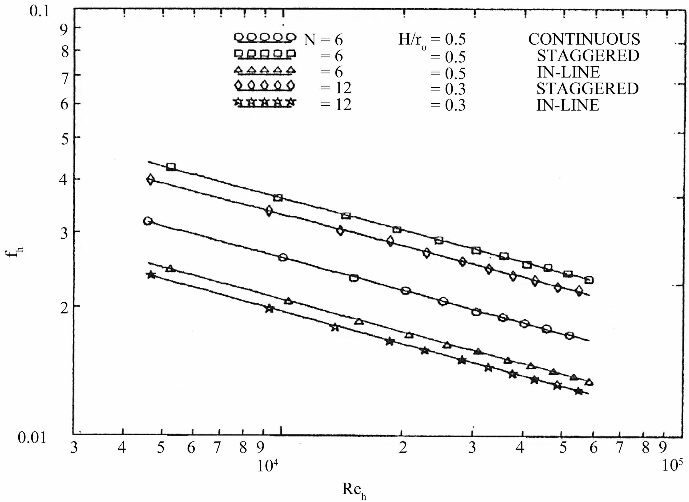
Figure 5. Module-averaged friction factor in the periodic fully developed region as a function of the hydraulic Reynolds number for all tested finned tubes.
aged friction factor in the periodic fully developed region for all tested tubes. The value of (fh) for the tubes with staggered arrangement is highly higher than that for tubes with in-line arrangement. This is because of increasing the area available for friction as well as increasing the number of leading and trailing edges of the fins, for two successive modules. The value of (fh) for the tubes with the staggered arrangement is higher than that for the tubes with continuous fins. Because staggering of the fins causes extra friction on the fin surface at the starting of each module. As the number of fins increases, the available area for friction increases and so the values of (fh) increase. Figure 6 shows the module-averaged friction factor based on the plain tube diameter for all tested finned and plain tubes. It is found that the values of (f) are 1.6, 2.0, and 2.8 of that for the plain tube for inline, continuous and staggered arrangement, respectively.
Regarding to (B), Figures 7 to 9 show the dimensionless pressure drop against the dimensionless axial distance ( ) for all tested finned tubes. The flow characteristics exhibit a periodically repeating behavior after some initial developing region. For periodic geometries of the type considered here, the fully developed pressure distribution along the tube versus axial distance is not a straight line as for conventional duct flows. The pressure distribution lies on a straight line in the fully developed region at axial stations x, (x + 2L), (x + 4L), etc. Since the average friction, factor decreases with increasing Re, so the pressure increases. Except for the first module, the pressure at the successive module ends decrease linearly along the tested interrupted finned tubes. For all tested finned tubes, it can be seen that the pressure drop for the staggered arrangement is larger than that for the in-line arrangement, while the continuous fins tube lies in between.
Regarding to (C), the augmentation of heat transfer caused by the additional of continuous fins on the inside of a circular tube surface, is significant. The module-averaged Nusselt number for all tested interrupted finned tubes is always lower than that for continuous fins tube. This may be attributed to the effect that the addition of fins with more interruptions causes the axial flow to escape from the tube wall and fin surface to the core region and thus reduces the washing flow on these surfaces. Figure 10 shows the module-averaged Nusselt number (based on hydraulic diameter) as a function of hydraulic Reynolds number in the thermally periodic fully developed region for all tested finned tubes. The solid lines represent the fin efficiency of the analytical conventional model (η < 1), while the dashed lines represent the fin efficiency model (η = 1).
From the experimental results, it is found that the Nusselt number versus Reynolds number for each tested finned tube can be represented by straight line, in a loglog scale so that the power-low can be used as follows;
 (23)
(23)
where (c) and (n) may be determined from the least square fit. Further more, for each arrangement (staggered or in-line) the straight lines for two test geometries are nearly parallel. The constant n and c in the power-low representation differ slightly for η =1 and η < 1 models as shown in Table 2.
For comparison with the plain tube, the module-aver-
Figure 6. Module-averaged friction factor in the periodic fully developed region as a function of Reynolds number for all tested finned tubes.
Figure 7. Axial variation of the module-averaged dimensionless pressure drop (In-line arrangement: N = 6, and  = 0.5).
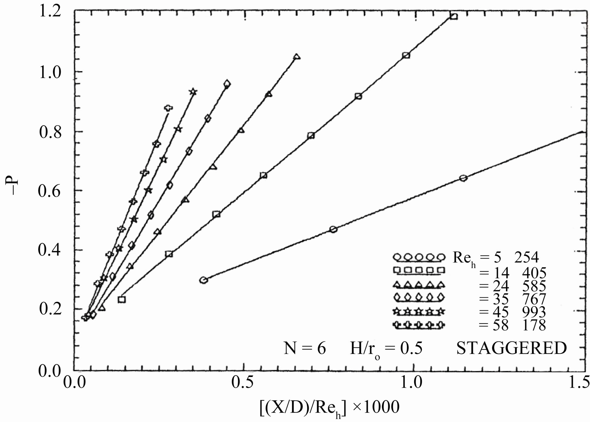
Figure 8. Axial variation of the module-averaged dimensionless pressure drop (Staggered arrangement: N = 6, and  = 0.5).
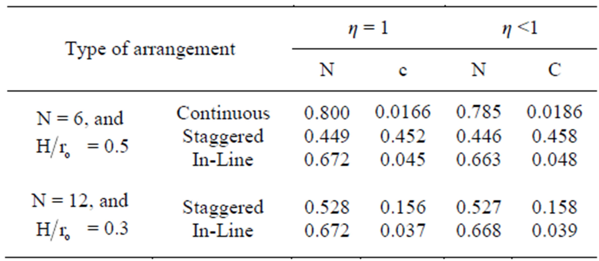
Table 2. Values of constants (c) and (n) of Equation (23).
aged Nusselt number is calculated based on the plain tube diameter. Figure 11 shows the module-averaged Nusselt number (based on the plain tube diameter) in the periodic thermally fully developed region for all tested finned tubes. The values of module-averaged Nusselt number for the in-line arrangement tubes are higher than those for the staggered arrangement tubes, at high Reynolds number, (Reh > 3.2 × 10⁴) for (N = 6, and  =
=
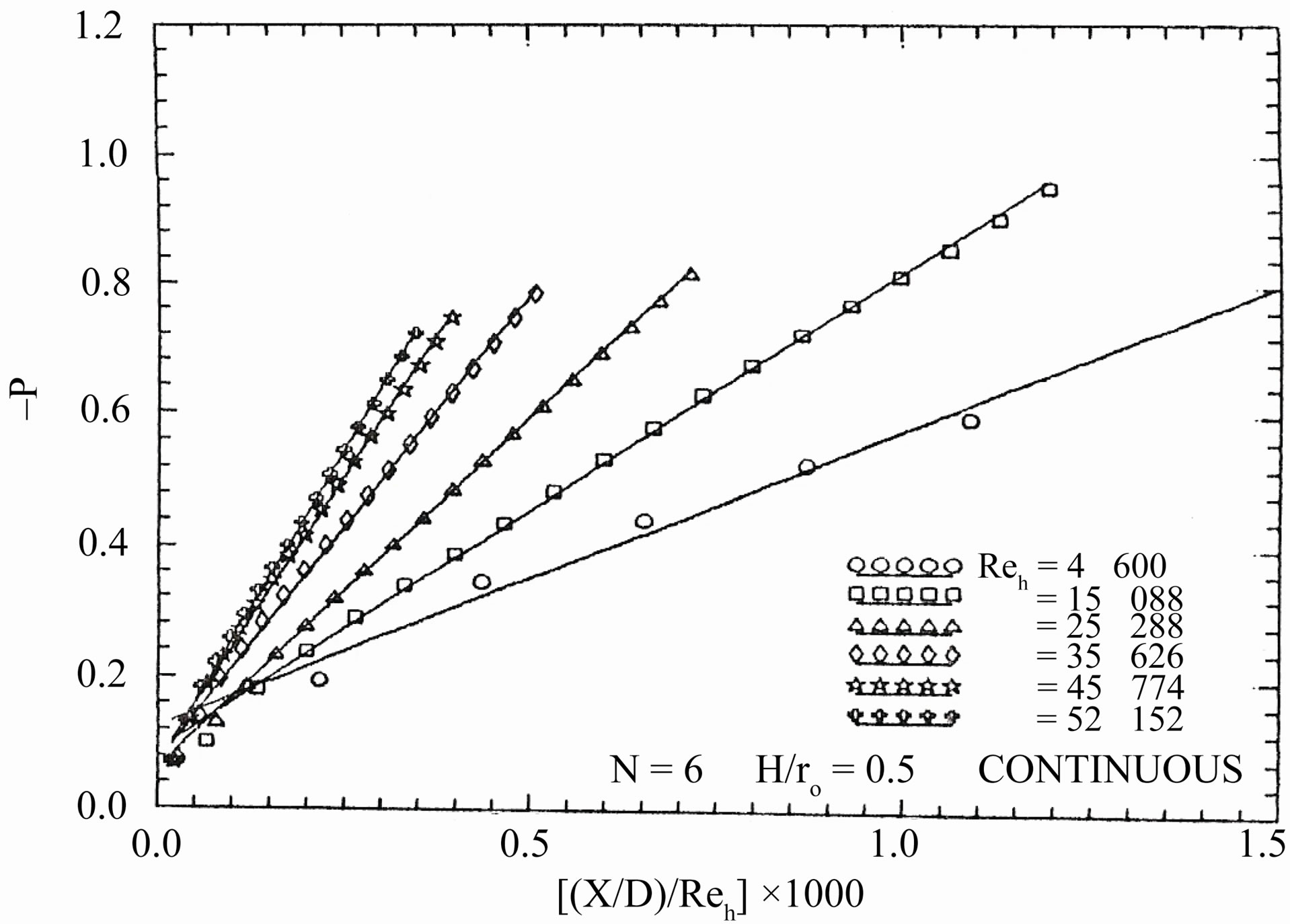
Figure 9. Axial variation of dimensionless pressure drop (continuous fins: N = 6, and  = 0.5).
0.5) and (Reh > 2 × 10⁴) for (N = 12, and  = 0.3). On the other hand, the values of the module-averaged Nusselt number for staggered arrangement tubes are higher than those for a tube with continuous fins at low Reynolds number (Reh > 1.2 × 10⁴) for (N = 6, and
  = 0.5). Also, geometry 1) for both arrangements (staggered and in-line) have higher values of module averaged Nusselt number than that for geometry 2). The effective values of module-averaged Nusselt number for the inline arrangement, which can be compared with the corresponding values for the others arrangements are obtained by averaging the values of two successive modules with and without fins.
Regarding to (D), the module-by-module heat transfer results are presented in Figures 12 to 16 for all tested finned tubes. In these figures several general characteristics of the results are evident. It is noticed that for all tested interrupted finned tubes, the module-averaged Nusselt number decreases from module to module in the stream wise direction until it reaches an asymptotic value, then it remains constant regardless of the module number. It is also shown that the value of Nusselt number increases with increasing the value of Reynolds number.
Two conflicting factors may be identified, which influence the variation of Nusselt number in the thermal entrance region. One of these factors is resulting from the module-by-module development of pattern of flow acceleration, wake shedding and impingement, which augment the heat transfer. The other factor is resulting from the migration of flow from the relative constrained inter-fin region to the core region. This migration occurs in the initial part of the fins array and then ceases as the flow becomes periodic thermally fully developed. Thus, the conflicting effects of the two factors discussed here are clear; one tends to increase the heat transfer, and the other tends to decrease it.
The number of modules, in the thermal entrance region,
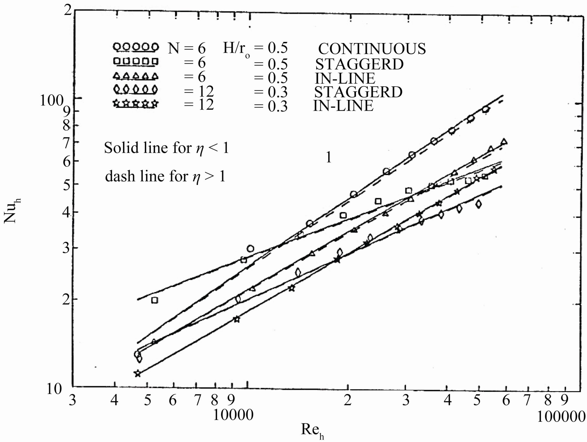
Figure 10. Module-averaged Nusselt number in the periodic fully developed region as a function of Reynolds number for all tested finned tubes.
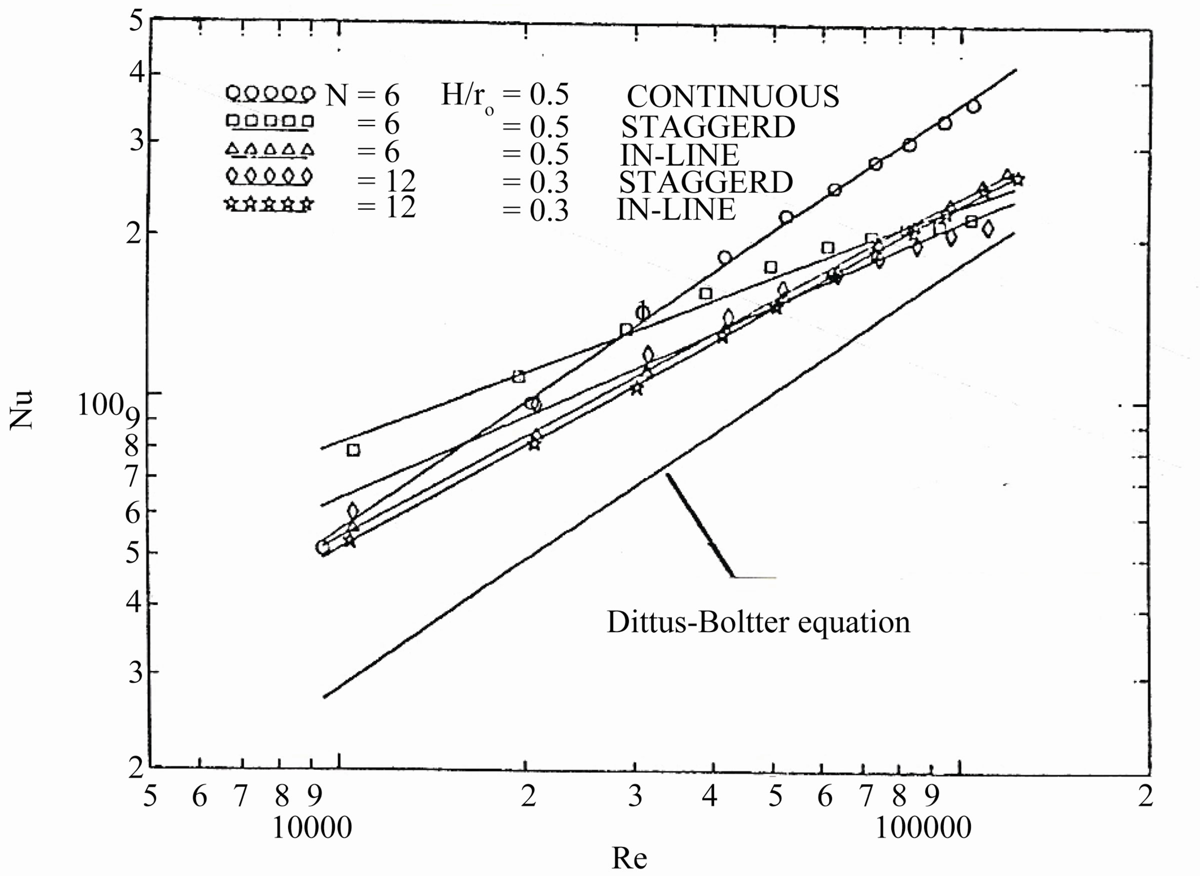
Figure 11. Module-averaged Nusselt number in the periodic fully developed region as a function of Reynolds number for all tested finned tubes.
required to make the flow periodic thermally fully developed depends on the fin height, the number of fins, the arrangement manner, and the Reynolds number. It is desired to have an overall indication of the thermal entrance region that will serve for all tested finned tubes investigated. The number of modules required for the flow to be periodical, thermally fully developed extends from about 8 to 12 modules. For the in-line arrangement, the value of the module-averaged Nusselt number is averaged over two successive modules, so that the value of (Nu) at even values of (M) only is meaningful.
Regarding to (E), the local Nusselt number along the module in the stream wise direction is shown for five values of the Reynolds numbers in Figures 17 and 18 as an example for the staggered and in-line arrangements for geometry 1) (N = 6, and  = 0.5). In the in-line arrangement as shown in Figure 17, the local Nusselt number along the module is calculated for two successive modules (finned and un-finned). The results show that, the value of the local Nusselt number in the finned module is slightly higher than that in the un-finned module. Moreover, if the Nusselt number is calculated based on the hydraulic diameter, the increase in Nusselt number in the finned module becomes larger than that in the un-
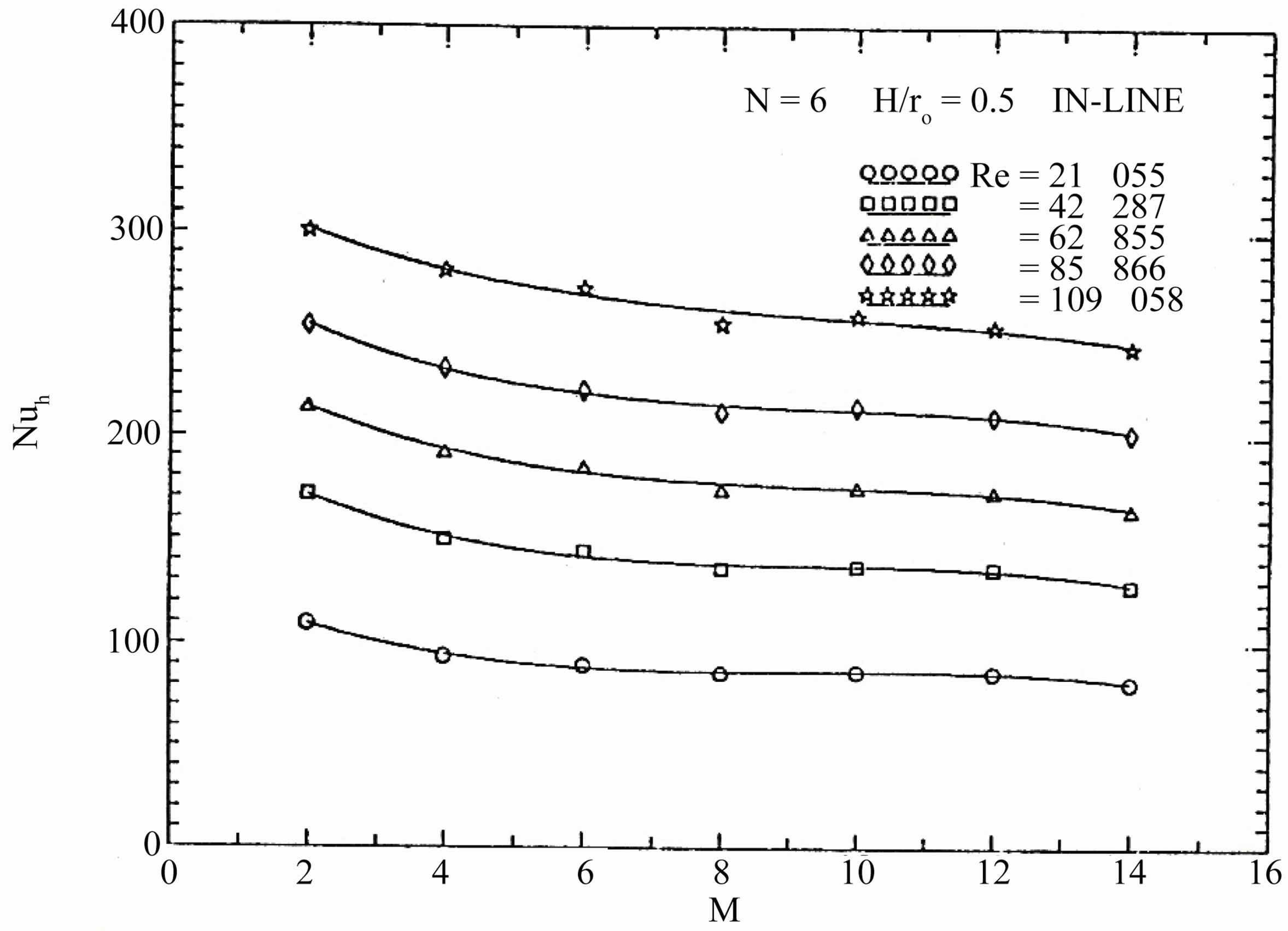
Figure 12. variations of the module-averaged of Nusselt number with number of modules.
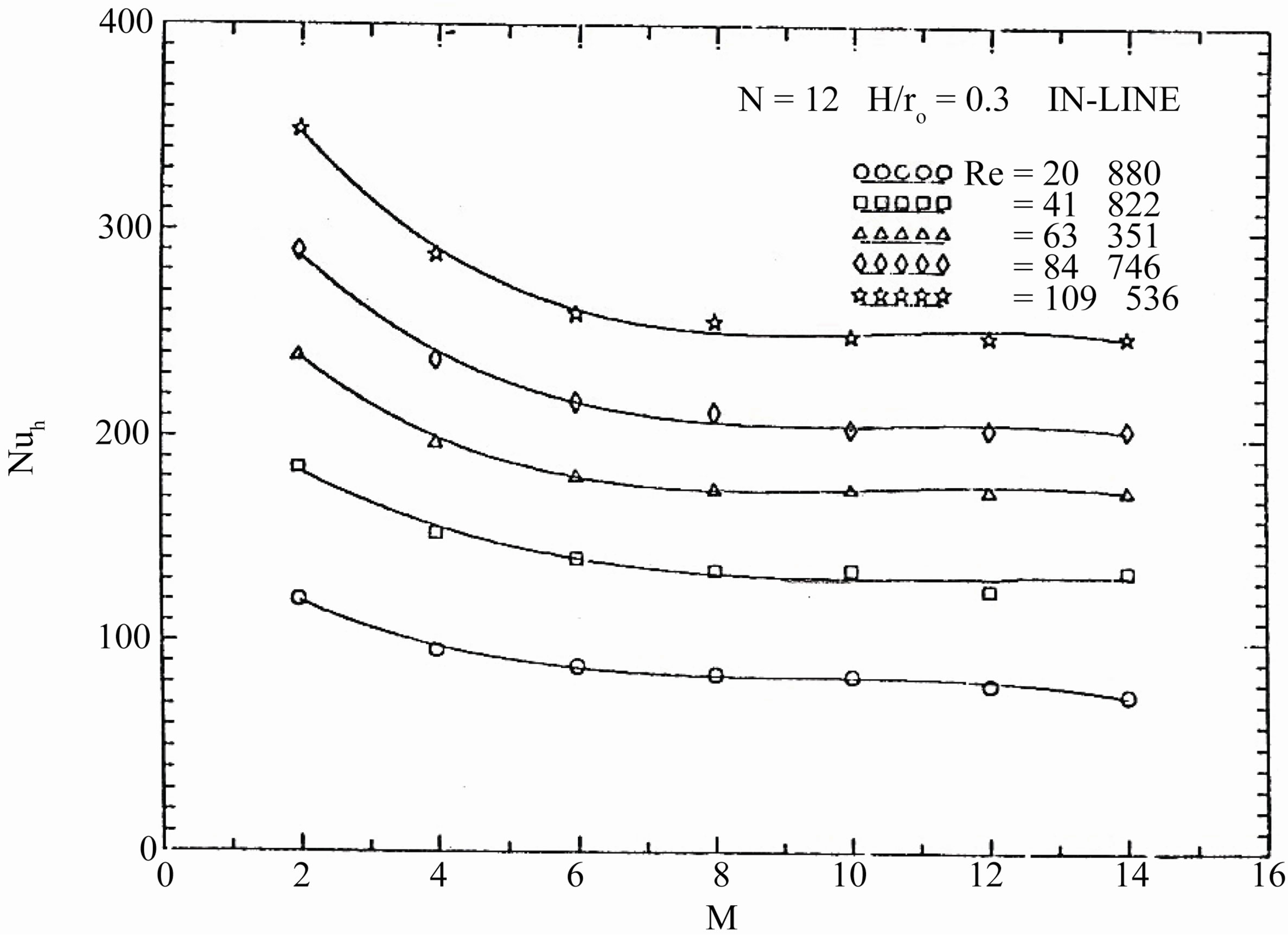
Figure 13. Variations of the module-averaged of Nusselt number with number of modules.
finned module. The value of the Nusselt number at the finned module entrance is slightly higher than that at the finned module exit. This is because the thermal boundary layer thickness is very thin at the leading edge of the fins. The value of the Nusselt number after the finned module exit is decreased suddenly, due to the absence of the fins in the un-finned module. Finally, the Nusselt number can be considered almost uniform along the finned module, and then dropped to another value in the un-finned module. This uniformity comes from the fact that in a short module, the growth of the thermal boundary layer thickness may not reach to large values along its length.
In the staggered arrangement as shown in Figure 18, the values of local Nusselt numbers at both of the module entrance and exit are higher than that at the middle of the module. Because the module has more heat transfer area at both the module entrance and exit. Also, both the module entrance and exit have high level of the turbulence due to increasing the number of fins cuts.
Regarding to (F), fin efficiency measurements are difficult to be obtained. Because the temperature measurements within the fin or on its surface are inherently difficult, using the available techniques, to be made without disruption of the heat transfer behavior. Thermocouples on the surface can significantly alter the flow and heat transfer over the surface, and thermocouples within the fin alter its heat conduction behavior. Analytical models of heat exchanger can be used to predict the efficiency with suitable accuracy. These models incorporate several simplifying assumption. The mainly
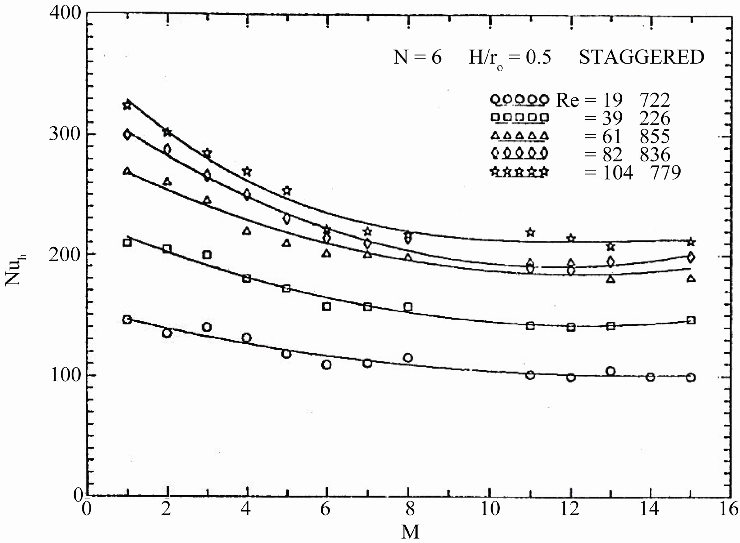
Figure 14. variations of the module-averaged of Nusselt number with number of modules.
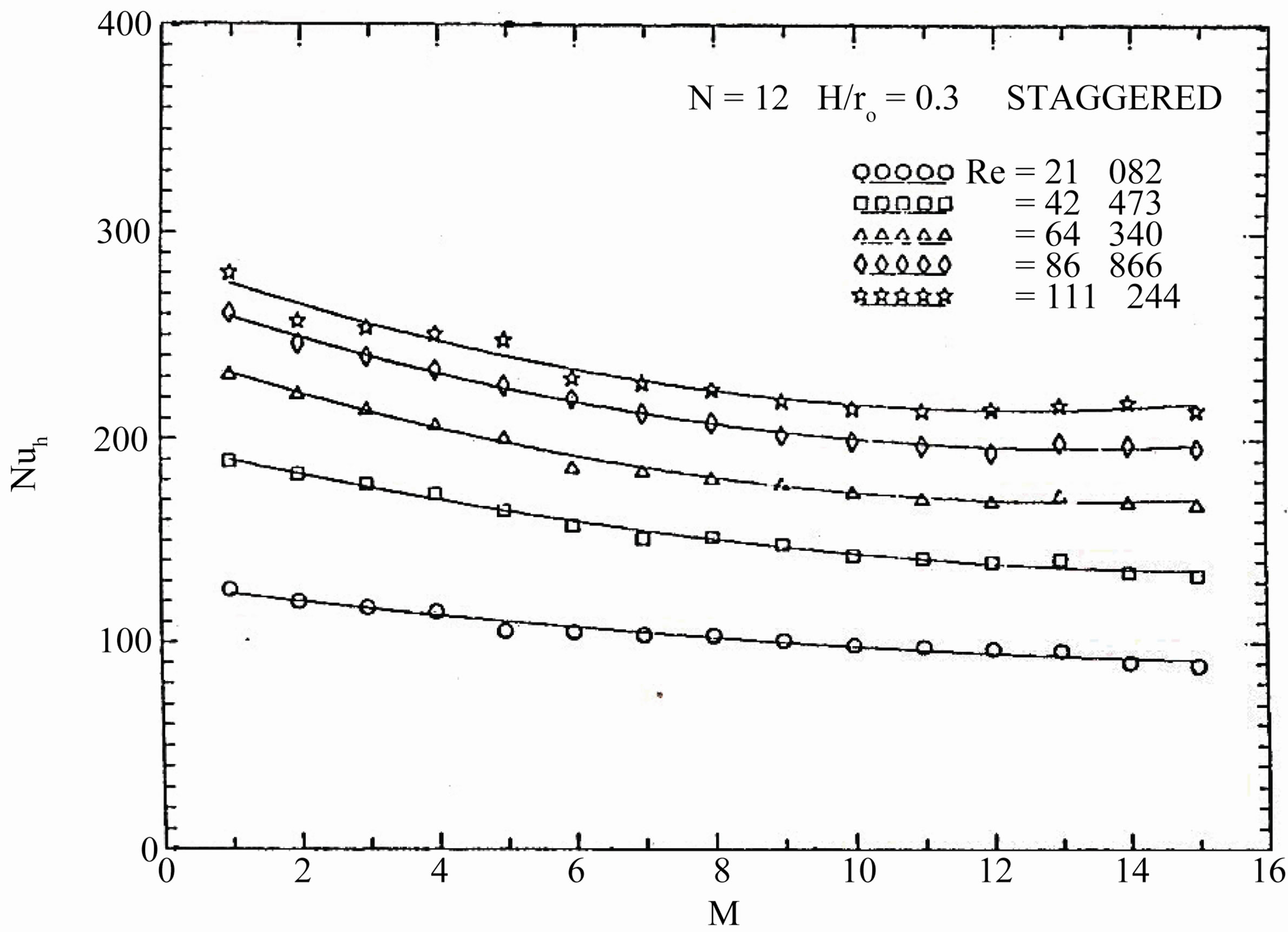
Figure 15. Variations of the module-averaged of Nusselt number with number of modules.
one considered that the temperature distribution within the fin is one-dimensional in the direction of heat flow. In addition, the expressions for evaluating the fin efficiency ignore the existence of wall and the other resistance affecting the heat flow. Figure 19 presents the fin efficiency, calculated from the iterative method, as a function of Reynolds number based on the plain tube diameter, for all tested finned tubes. Figure 20 conveys the fin temperature distributions which are plotted in the dimensionless from  versus the dimensionless distance
 . As expected, the values of efficiency are substantially lower for the longer fins. In particular, the value of efficiency for fins with
  = 0.3 generally exceeded 98 percent, while values as high as 94 percent obtained for fins with
  = 0.5, for both arrangements at the maximum Reynolds number. The continuous fins tube has lower values of η than that of the interrupted finned tubes, because its fins efficiency is calculated in the fully developed region. But for interrupted finned tubes, each fin can be dealt as if it is in the entrance regions. It is seen that the fin efficiency decreases with increasing Reynolds number. This is due to the increase in the air mass flow rate that increases the heat transfer coefficient.
7. Conclusions
The heat transfer for turbulent flow in a circular tube with staggered and in-line arrangements of longitudinal
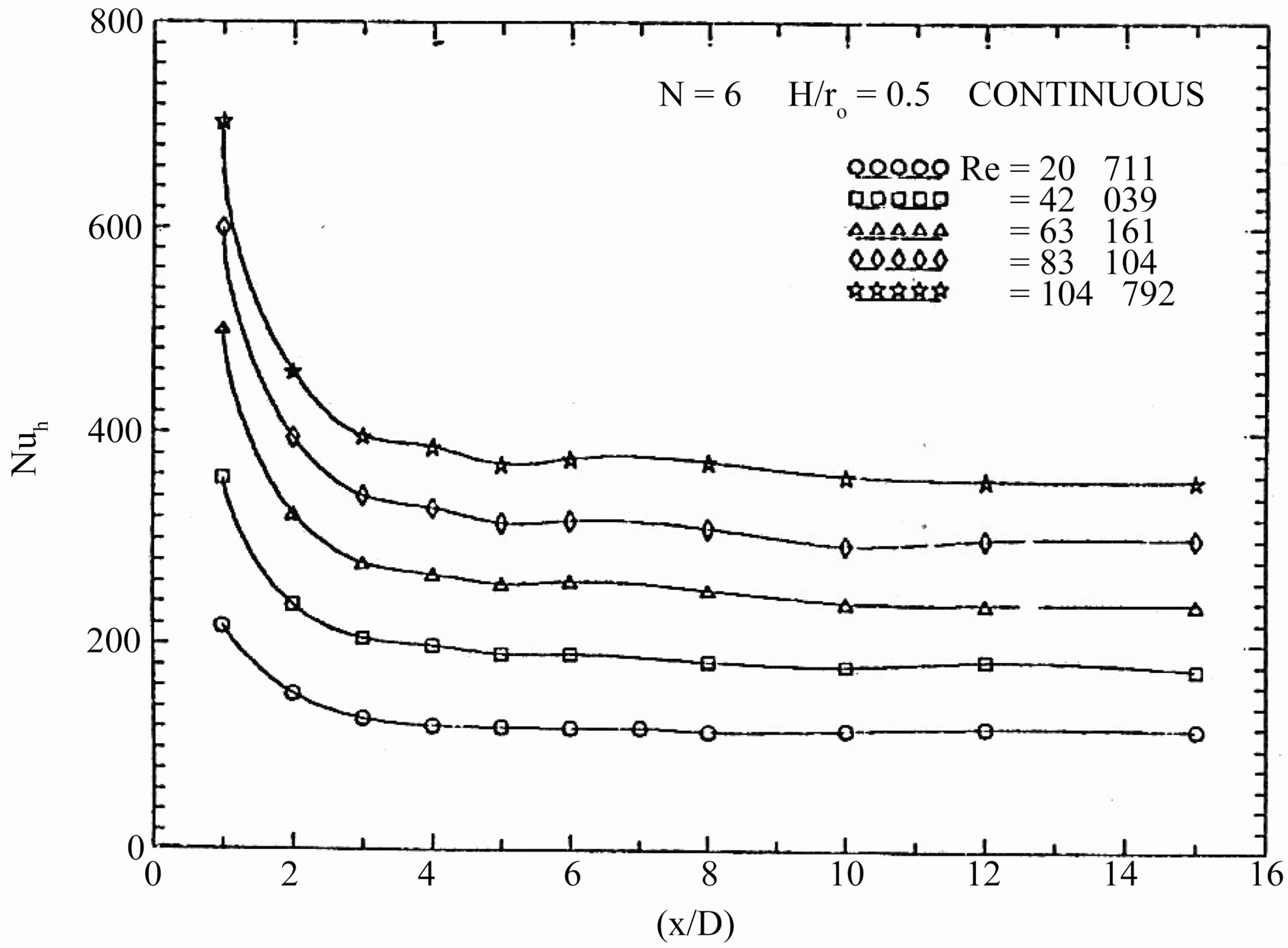
Figure 16. Variations of Nusselt number with the dimensionless axial length.
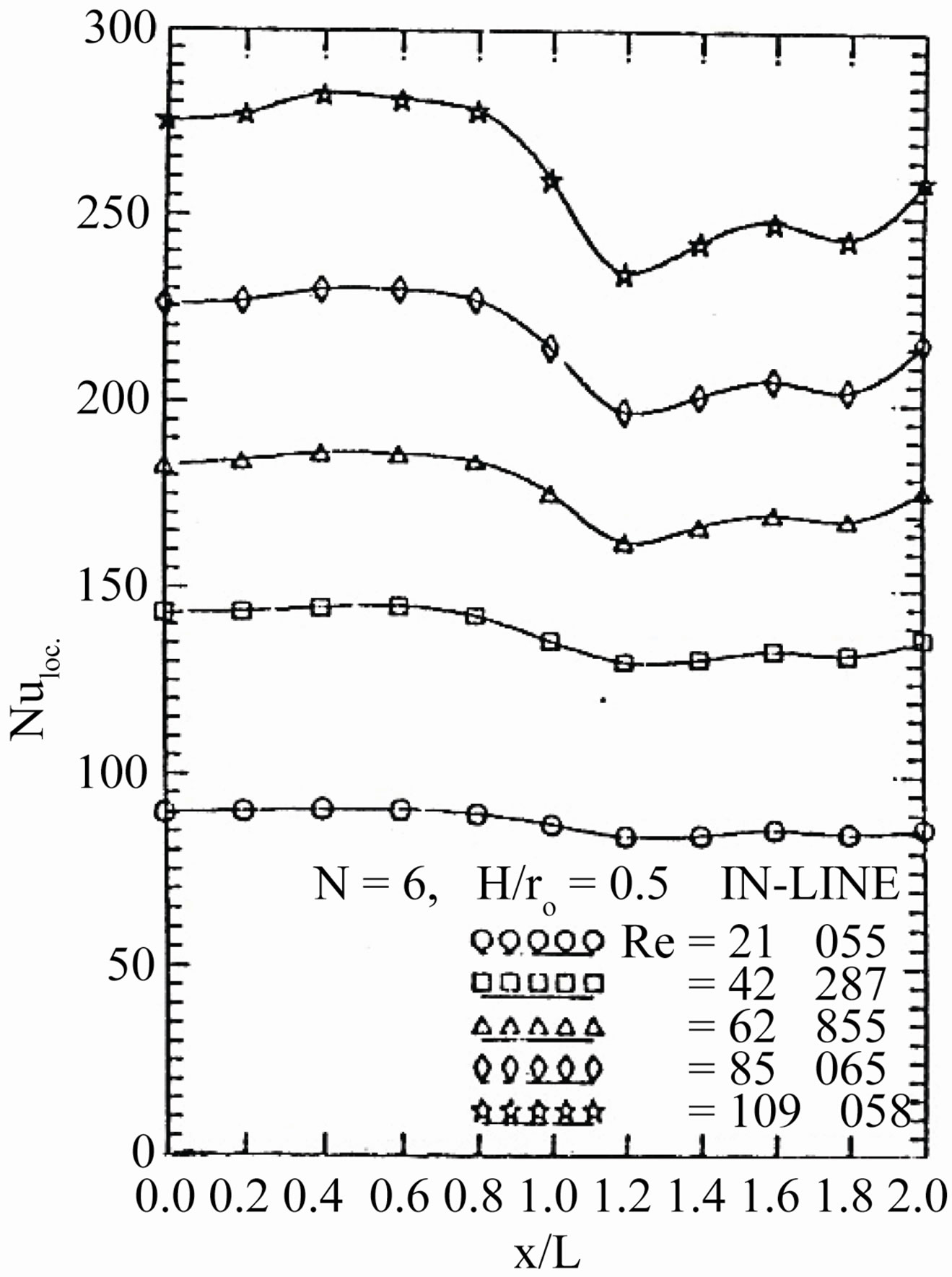
Figure 17. Variations of the local Nusselt number with the dimensionless axial module length.
continuous and interrupted fins on the inside surface of the tube is investigated experimentally. The experiments are performed to determine the detailed module-bymodule heat transfer characteristics. Detailed temperature measurements are made, from which the moduleaveraged Nusselt number are determined. As results of the present study, the following conclusions are derived:
1) The results showed that in the periodic hydrodynamic fully developed region, the value of the pressure drop along a tube with continuous fins is higher than that of the in-line arrangement, and lower than that of the staggered arrangement.
2) After a certain initial length, the flow characteristics
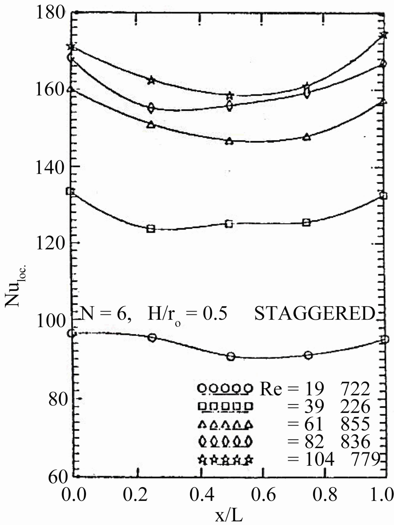
Figure 18. Variations of the local Nusselt number with the dimensionless Axial module length.
show periodically repeating behavior due to the periodicity in the geometry. Results showed that the moduleaveraged Nusselt number starts with a high value and then decreases gradually towards an a symptomatic value, which relates to the thermal periodic fully developed flow. The number of modules required for the flow to become thermally periodic fully developed extends from about 8 to 12 modules.
3) The values of the module-averaged Nusselt number for the tube with in-line arrangement fins are higher than that of the staggered arrangement, at high Reynolds numbers, (5 × 10⁴ > Reh > 3.2 × 10⁴) for geometry (1) (n = 6,  = 0.5) and (5 × 10⁴ > Reh > 2 × 10⁴) for ge-
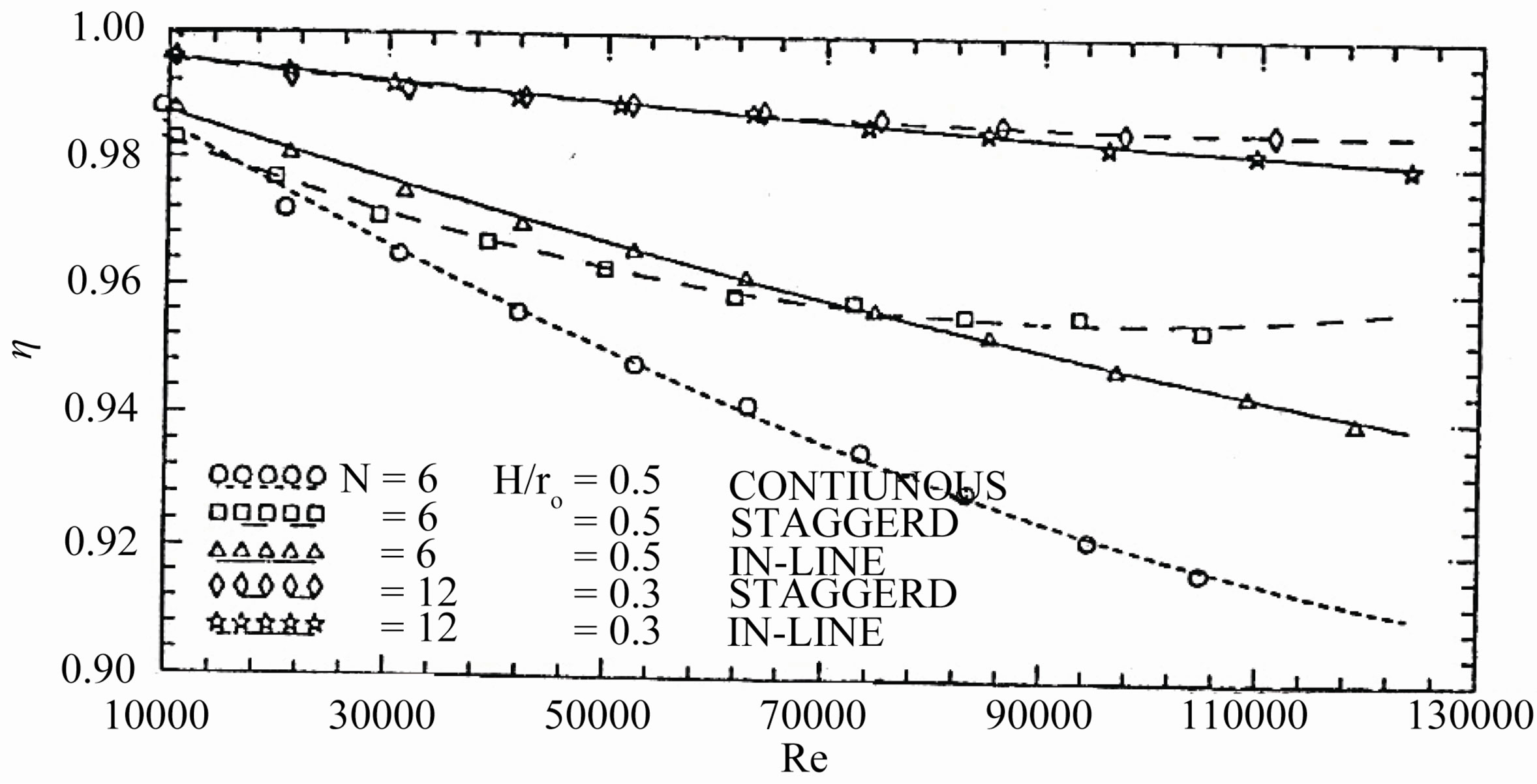
Figure 19. Fin efficiency for all tested finned tubes with Reynolds number.
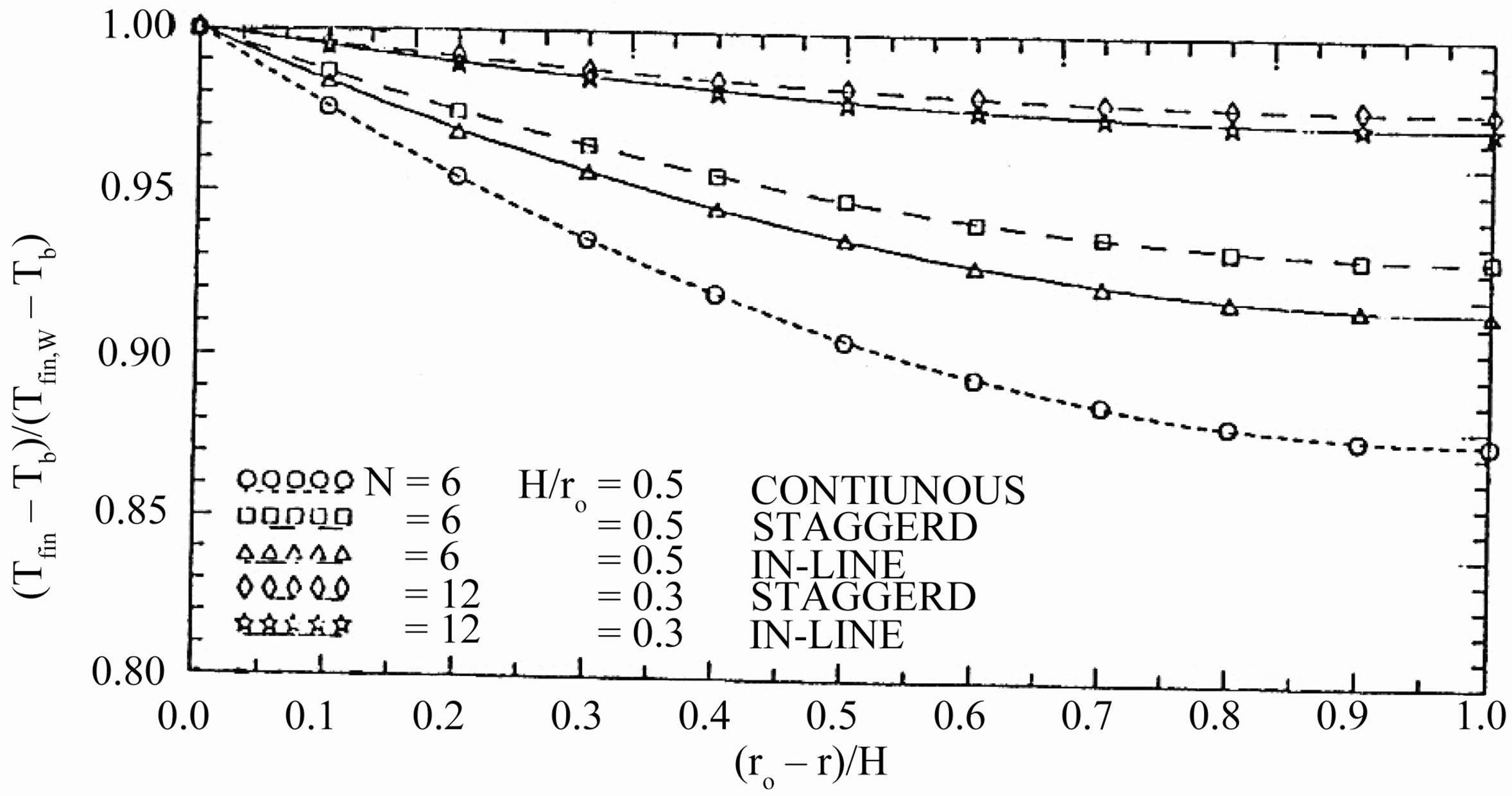
Figure 20. Fin temperature distributions in the radial direction for all tested finned tubes for Re = 1.1 × 10⁵.
ometry (2) (N = 12, and  = 0.5).
4) The values of module-averaged Nusselt number for staggered arrangement tubes are higher than that for a tube with continuous fins at low Reynolds numbers (Reh > 1.2 × 10⁴) for geometry (1) (N = 6, and  = 0.5).
5) For both arrangements (staggered and in-line), geometry (1) (N = 6, and  = 0.5) has higher values of the Nusselt number than that for geometry (2) (N = 12, and
  = 0.3).
6) The augmentation of heat transfer caused by the addition of continuous fins inside a circular plain tube is significant. The value of the module-averaged Nusselt number, for a tube with continuous fins is about one and half that for the plain tube. The tested interrupted finned tubes have module-averaged Nusselt number equal to about one and third that for the plain tube.
REFERENCES
- I. M. Rustom and H. M. Soliman, “Numerical Analysis of Laminar Forced Convection in the Entrance Region of Tubes with Longitudinal Internal Fins,” ASME Journal of Heat Transfer, Vol. 110, No. 2, 1988, pp. 310-313. doi:10.1115/1.3250485
- A. Campo and J. C. Morales, “Analysis/Numerical Prediction of the Three-Dimensional Temperature Variation in Tube Having Stream Wise Internal Fins,” Journal of Numerical Heat Transfer, Part A: An International Journal of Computation and Methodology, Vol. 23, No. 3, 1993, pp. 319-339. doi:10.1080/10407789308913675
- C. Prakash and Y. D. Liu, “Analysis of Laminar Flow and Heat Transfer in the Entrance Region of an Internally Finned Circular Tubes,” ASME Journal of Heat Transfer, Vol. 107, No. 1, 1985, pp. 84-91. doi:10.1115/1.3247407
- D. Choudhury and S. V. Patankar, “Analysis of Laminar Flow and Heat Transfer in Tubes with Radial Internal Fins,” Proceedings of the 23rd National Heat Transfer Conference, Denver, 1985, pp. 57-64.
- N. H. Hu and Y. P. Chang, “Optimization of Finned Tubes for Heat Transfer in Laminar Flow,” ASME Journal of Heat Transfer, Vol. 95, No. 3, 1973, pp. 332-338. doi:10.1115/1.3450060
- J. H. Masliyah and K. N. Nandakumer, “Heat Transfer in Internally Finned Tubes,” ASME Journal of Heat Transfer, Vol. 98, No. 5, 1976, pp. 257-261. doi:10.1115/1.3450528
- H. M. Soliman, T. S. Chau and A. C. Trupp, “Analysis of Laminar Heat Transfer in Internally Finned Tubes with Uniform outside Wall Temperature,” ASME Journal of Heat Transfer, Vol. 102, No. 4, 1980, pp. 598-604. doi:10.1115/1.3244358
- S. V. Patankar, M. Ivanovic and E. M. Sparrow, “Analysis of Turbulent Flow and Heat Transfer in Internally Finned Tubes and Annuli,” ASME Journal of Heat Transfer, Vol. 101, No. 1, 1979, pp. 29-37. doi:10.1115/1.3450925
- N.-H. Kim and R. L. Webb, “Analytic Prediction of the Friction and Heat Transfer for Turbulent Flow in Axial Internal Fin Tubes,” ASME Journal of Heat Transfer, Vol. 115, No. 3, 1993, pp. 553-559. doi:10.1115/1.2910723
- E. M. Sparrow, B. R. Baliga and S. V. Patankar, “Heat Transfer and Fluid Analyses of Interrupted Wall Channels, with Application to Heat Exchangers,” ASME Journal of Heat Transfer, Vol. 99, No. 1, 1977, pp. 4-11. doi:10.1115/1.3450654
- E. M. Sparrow and C. H. Liu, “Heat Transfer, Pressure Drop and Performance Relationships for In-Line, Staggered, and Continuous Plate Heat Exchangers,” International Journal of Heat and Mass Transfer, Vol. 22, No. 12, 1979, pp. 1613-1625. doi:10.1016/0017-9310(79)90078-4
- A. L. London and R. K. Shah, “Offset Rectangular PlateFin Surface-Heat Transfer and Flow Friction Characteristics,” ASME Journal of Engineering for Power, Vol. 90, 1968, pp. 218-228.
- H. M. Joshi and R. L. Webb, “Heat Transfer and Friction in the Offset Stripfin Heat Exchanger,” International Journal of Heat and Mass Transfer, Vol. 30, No. 1, 1987, pp. 69-84. doi:10.1016/0017-9310(87)90061-5
- S. V. Patankar and C. Prakash, “An analysis of the Effect of Plate Thickness on Laminar Flow and Heat Transfer in Interrupted-Plate Passage,” International Journal of Heat and Mass Transfer, Vol. 24, No. 11, 1981, pp. 1801-1810. doi:10.1016/0017-9310(81)90146-0
- K. M. Kelkar and S. V. Patankar, “Numerical Prediction of Heat Transfer and Fluid Flow in Rectangular Offset-Fin Arrays,” Journal of Numerical Heat Transfer, Part A: Applications: An International Journal of Computation and Methodology, Vol. 15, No. 2, 1989, pp. 149- 164. doi:10.1080/10407788908944682
- H. M. Joshi and R. L. Webb, “Heat Transfer and Friction in the Offset Strip-Fin Heat Exchanger,” International Journal of Heat and Mass Transfer, Vol. 30, No. 1, 1987, pp. 69-84. doi:10.1016/0017-9310(87)90061-5
- K. M. Kelkar and S. V. Patankar, “Numerical Prediction of Fluid Flow and Heat Transfer in a Circular Tube with Longitudinal Fins Interrupted in Stream Wise Direction,” ASME Journal of Heat Transfer, Vol. 112, No. 2, 1990, pp. 342-348. doi:10.1115/1.2910383
- X. Liu and M. K. Jensen, “Geometry Effects on Turbulent Flow and Heat Transfer in Internally Finned Tubes,” ASME Journal of Heat Transfer, Vol. 123, No. 6, 2001, pp. 1035-1044. doi:10.1115/1.1409267
- S. K. Saha and P. Langille, “Heat Transfer and Pressure Drop Characteristics of Laminar Flow through a Circular Tube with Longitudinal Strip Inserts under Uniform Wall Heat Flux,” ASME Journal of Heat Transfer, Vol. 124, No. 3, 2002, pp. 421- 432. doi:10.1115/1.1423907
- O. Zeitoun and A. S. Hegazy, “Heat Transfer for Laminar Flow Internally Finned Pipes with Different Fin Heights and Uniform Wall Temperature,” Journal of Heat and Mass Transfer, Vol. 40, No. 3-4, 2004, pp. 253-259. doi:10.1007/s00231-003-0446-8
- W. M. Kays, “Convective Heat and Mass Transfer,” McGraw-Hill, Boston, 1966.
- W. M. Kays and H. G. Perkins, “Handbook of Heat Transfer,” McGraw-Hill, Boston, 1972.
- M. N. Ozisik, “Basic Heat Transfer,” McGraw-Hill, Boston, 1977.
- F. M. White, “Heat Transfer,” Addison-Wesley, Boston, 1984.
Nomenclature
A = Area, m2.
Ac = Minimum cross-sectional area of the tested finned tubes, m2.
Cd = Discharge coefficient of orifice meter.
cp = Specific heat of the air at constant pressure, J/Kg·k.
D = Inner diameter of the tested finned tubes, m.
Dh = Hydraulic diameter of the tested finned tube, m.
h = Local heat transfer coefficient, W/m2·K.
H = Height of the fin, m.
M = Number of modules.
N = Number of fins.
Nu = Nusselt number based on the plain tube diameter.
Nuh = Nusselt number based on the hydraulic diameter.
P = Wetted perimeter (m).
Pe = Peclet number (Pe = Re·Pr).
Pr = Prandtl number.
qc = Convection heat transfer, W.
r = Radial coordinate.
ro = Inner radius of the tested finned tubes, m.
Re = Reynolds number based on the plain tube diameter.
Reh = Reynolds number based on the hydraulic diameter.
T = Temperature, K.
v = Velocity, m/s.
x = Axial coordinate.
Greek Letters
η = efficiency of the fin.
μ = Viscosity, kg/m·s.
ρ = Density, kg/m3.
Subscripts and Superscripts
a = Air.
b = Bulk.
e = Entrance/exit conditions.
Fin, loc. = Fin local.
Fin, w = at the fin base.
i = Inlet condition.
L = Module.
o = Outlet condition.
w = Wall.
NOTES
*Corresponding author.