Advances in Materials Physics and Chemistry
Vol.07 No.04(2017), Article ID:75403,14 pages
10.4236/ampc.2017.74009
Study of the Contact and the Evaporation Kinetics of a Thin Water Liquid Bridge between Two Hydrophobic Plates
Etienne Portuguez1, Arnaud Alzina1, Philippe Michaud1, Djamila Hourlier2, Agnès Smith1*
1Université de Limoges, SPCTS, CNRS, ENSCI, Limoges, France
2 Institut d’Electronique, de Micro-électronique et de Nanotechnologie, CNRS, VILLENEUVE d’ASCQ, France
![]()
Copyright © 2017 by authors and Scientific Research Publishing Inc.
This work is licensed under the Creative Commons Attribution International License (CC BY 4.0).
http://creativecommons.org/licenses/by/4.0/


Received: December 15, 2016; Accepted: April 8, 2017; Published: April 14, 2017
ABSTRACT
The evaporation of sessile water droplets on hydrophobic surfaces is a topic which led to numerous investigations. However, how does the liquid behave when the evaporation occurs between two of these particular substrates? The drying stage is governed by capillary phenomena which takes place in a confined space. In the field of material shaping, it is also possible that some regions of a green body exhibit hydrophobic properties. As part of a better understanding of the local mechanisms during drying, liquid bridges have been reproduced in an ideal case. Drying kinetics and parameters measurements from 303 to 343 K (relative humidity of 55%) of deionized water liquid bridges between two plates of hydrophobic substrates are presented. Experi- mental work was carried out using a specific device to create liquid bridges, coupled with image analysis within an adapted instrumented climatic cham- ber. While the volume and the exchange surface of liquid bridges decrease regularly throughout the process, contact angles constantly diminish and more significantly at the end. This is different from the evaporation between two hydrophilic plates. From these measurements, the change of curvature of the liquid bridges during evaporation is highlighted.
Keywords:
Liquid Bridge, Hydrophobic Substrate, Volume, Contact Angle, Evaporation

1. Introduction
Hydrophobic materials arouse interest as their applications are widespread, from limiting friction in the aeronautic field, self-cleaning surfaces or modifying heat transfer properties. The main interesting characteristics are then the static contact angle and tilting angles. However, how does the liquid evaporate from these surfaces? The behavior of a liquid deposited on a solid substrate depends on its wetting properties. The investigation of liquid/solid interfaces was widely discussed in the literature [1] [2] , but still remains a current topic. Wetting phenomena, and the resulting surface forces are responsible for many crucial effects in material science, such as capillary actions (adhesion forces between a liquid and a solid or between two solids) and dynamic liquid flow (impregnation, drying) [3] [4] . Among the different types of contacts that can be realized, an increasing interest appears for the study of hydrophobic surfaces (contact angle with water > 90˚) [5] [6] [7] . These surfaces often mimic nature, for instance the super-hydro- phobic surface of a lotus leaf (Figure 1(a)). Such materials can be created using several methods, among which surface treatments, coatings or by controlling the initial composition. These water-repellent surfaces have widespread and practical applications, as self-cleaning materials, limiting the fog or the deposition of dirt, preventing frost formation. Recently, hydrophobic materials, coatings, textured surfaces were used in microelectromechanical systems and in microfluidic fields. Indeed, they promote dropwise condensation instead of liquid spreading, which prevents water damage in electronics (Figure 1(b)). In the case of a microfluidic device, they greatly facilitate liquid flow by eliminating the capillary forces, whereas hydrophilic materials usually prevent liquid displacement at local scales (Figure 1(c)). In this study, the evaporation of liquid bridges between two hydrophobic substrates and under various temperatures of the drying air is investigated. In particular, focus is made on the local capillary phenomena during the departure of the liquid phase.
When temperature evolves, surface tension at the liquid/gas interface is modi- fied [8] . Recently, experimental studies pointed out that relative humidity was
 (a) (b) (c)
Figure 1.Three examples for the use of hydrophobic surfaces: (a) an almost spherical water droplet deposited on an hydrophobic lotus leaf, the leaf surface has a multiscale texturing with spikes at a micrometric scale and wires of stearic acid at a nanometric scale which produce superhydrophobicity (image acquistions realized with an optical camera and ESEM equipment described in the materials and methods section); (b) hydrophobic materials are used in electronic devices in order to prevent any damage from water or water based liquids; (c) microfluidic channel using hydrophobic materials in order to ease the flow in confined geometries.
also acting as a surfactant [9] [10] . This article provides new local data about the behavior of liquid bridges in hydrophobic contacts in a confined geometry. Such data could be used to create accurate numerical models based on representative experimental values of local scale mechanisms. To the best knowledge of the authors, the evaporation of liquid bridges between two hydrophobic substrates has never been reported in the literature, the only observations were on drying liquid bridges between hydrophilic substrates.
2. Materials and Methods
We encourage the interested reader to find more details about the specific device used in this study in our previous work [11] .
2.1. Climatic Chamber
Experiments are made within an environmental chamber presented in Figure 2, at a given temperature between 303 and 343 K (accuracy of 0.1 K) and a fixed relative humidity of 55% (accuracy of 0.1%) which are controlled by computer. The zero diopter glass door allows the observation of the liquid bridges during the drying stage.
In order to create liquid bridges in hydrophobic contacts, a specific module was created and is described in the following section.
2.2. Liquid Bridges Creation
A detailed view of the specific liquid bridges creation module is presented in Figure 3 and illustrated in the case of a liquid bridge between two hydrophobic substrates. This module includes a rotating movable part attached to a fixed

Figure 2. Experimental device for the observation of liquid bridges between hydrophobic plates.

Figure 3. Schematic representation of the liquid bridges module used to create menisci.
frame. The movable part can make a vertical translation using a 20 mm ± 1 μm of travel micrometer, and a rotation with an accuracy of 0.1˚ along an axis perpendicular to that of the translation. The two required substrates are fixed on the system and their parallelism is checked using the optical camera. After a pendant drop was slowly deposited on the lower substrate, the upper substrate is moved towards the drop and the liquid bridge is created. An Eppendorf Multipette® plus allowed to create pendant drops with an initial volume of 4 μL with a precision of 1%. Deionized water (conductivity < 1 mS∙m−1) was used for drops and for the water tank providing humidity into the climatic chamber, thus the studied liquid and surrounding vapor have the same composition. Water density is of 1.000 ± 0.005 g∙mL−1 at 293 K and for the presented work it can decrease to 0.977 ± 0.005 g∙mL−1 at 343 K.
2.3. Substrates
In this study, four different substrates have been used. To illustrate the transition between hydrophilic and hydrophobic contacts, silicon wafer substrates were used as hydrophilic substrates. The first hydrophobic surfaces are polytetrafluoroethylene (PTFE) substrates. Higher hydrophobic contacts were realized using organosiloxane based gel deposited on a PTFE coated silicon wafer. Finally, super-hydrophobic contacts were created on silicon wafers covered by a commercial polymer coating (Ultra Ever Dry®). This coating, deposited on both the bottom and the upper substrates, consists in applying two coats: afirst coat and a second coat which crosslinks to form a nanostructured layer. These different surfaces are presented on Figure 4.
2.4. Image Acquisition
A high resolution monochrome camera with charge-coupled device (CCD) was used, model UI-148SE-M from manufacturer IDS Imaging. The camera has a 5 M pixel 1/2" sensor, a resolution of 2560×1920 pixels and a rate of 6 images∙s−1. It was coupled with a QIOPTIC optical of 100 mm/0.062 1/2".
Microscope images were realized with an environmental scanning electron microscope (ESEM) QuantaTM 450 FEG. With this equipment, the substrates do not need to be metallized, so the surfaces are not altered before observation. Samples are just beforehand cleaned. Silicon wafers are cleaned with ultrasounds in an acetone bath and the surface is then washed with ethanol before being dried. PTFE substrates are cleaned with ultrasounds in an ethanol bath. The organosiloxanegel is washed with deionized water and the superhydrophobic coatings are used right after their preparation.
2.5. Liquid Bridge Volume and Area Evaluation
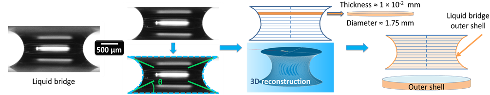
The volume and the area of the liquid bridge during drying are evaluated. These measurements consist in a three steps procedure. First, liquid bridges with an initial volume of 4.0 μL ± 0.1 μL were produced and observed during drying (varying the initial volume is investigated in our previous work in the case of hydrophilic contacts [11] ). The dimensions are given in Figure 5(a) in the case of a hydrophilic contact. Images were taken each minute and with a narrower interval of time at the end of drying. Then, pictures were cropped in order to retain the liquid part. A threshold allowed to detect the edge of the liquid bridge (Figure 5(b)). Using the 0.5 mm of distance between the two substrates as a standard to convert pixels values in meters, a computer program evaluates the volume and the area of the liquid bridge. More precisely, the liquid bridge was divided into subsections and a circular revolution allowed the evaluation of all
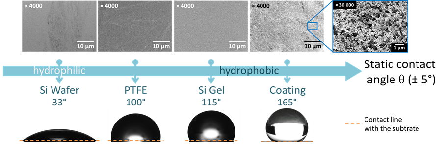
Figure 4. Presentation of the different surfaces and their ESEM images used in the present study: they allow to scan a large range of contact angles, from silicon wafer (33˚) to superhydrophobic coating (165˚), in order to compare the different evaporation kinetics.
 (a) (b) (c) (d)
Figure 5. Water liquid bridge volume and area evaluation in the case of an hydrophilic contact: (a) liquid bridge of deionized water; (b) cropped image, edge detection (dashed line) and evaluation of the four contact angles; (c) liquid bridge volume evaluation (gravity center in dashed line) and three-dimensionnal reconstruction; (d) liquid bridge outer shell evaluation (exchange surface). The same operation is realized on hydrophobic contacts.
the subvolumes. The volume then resulted from their addition. To be implemented, the present hypothesis consisted in local revolution symmetry. Volume comparisons at the initial time, where the introduced volume was known, indicated a volume measurement accuracy of ±0.1 μL.
The liquid bridge was then rebuilt in three dimensions (Figure 5(c)). Only the outer shell was retained in order to evaluate the exchange surface (Figure 5(d)).
Liquid bridges are observed until they break. No measurements are performed after the liquid bridges breaking. The measurements presented in the following section are realized at a fixed relative humidity of 55%.
3. Results and Discussion
3.1. Contact Angle Hysteresis
Before any evaporation study, the behavior between the different substrates was investigated at room temperature (293 K) by observing the contact angle hysteresis through compressing and stretching the deionized water menisci. Such measurements were recently studied in the literature and aim at evaluating the stability of the liquid bridges and how the liquid interacts with the substrates [12] [13] . After depositing a 4 μL droplet on the inferior substrate, the image acquisition starts when the liquid bridge is created. The liquid bridges are first compressed to a height value of 0.5 mm. Then, they are stretched until they break. From the initial contact, an image acquisition is performed every 0.1 mm. Compressing and stretching are realized at a speed of 0.01 mm∙s−1. The four observed contact angles are then measured by image analysis (±0.1˚) and plotted as a function of the separation between the two substrates. The results are presented in Figure 6, accompanied with the corresponding images. In the case of silicon wafer (Figure 6(a)), the four initial contact angles are about 42˚. By compressing the liquid bridges to a separation distance of 0.5 mm, contact angles slightly increase to 44˚. Then, stretching make them decrease to about 30˚. Finally, the contact angles remain constant with a value around 30˚ until the liquid bridge breaks.
For PTFE substrates (Figure 6(b)), upper and bottom contact angles do not behave in the same way. After the contact is realized, the upper contact angles
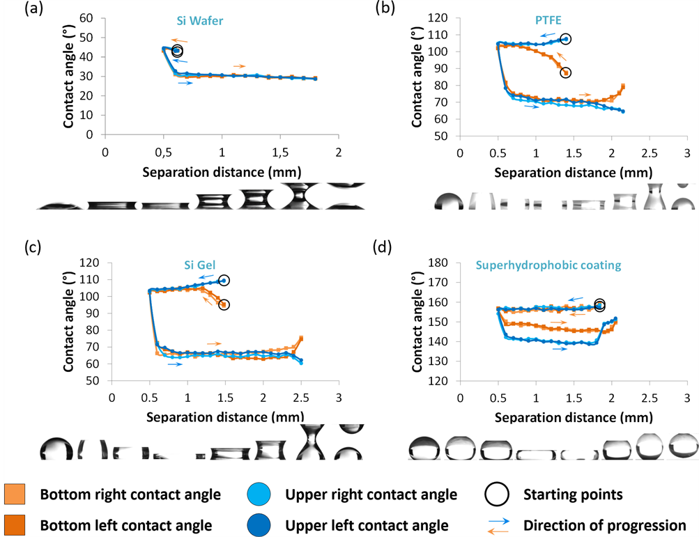
Figure 6. Evolution of the four contact angles of the liquid bridges during compressing and stretching of a water drop between four pairs of identical surfaces, at a fixed liquid bridge height of 0.5 mm, a fixed temperature of 293 K and a fixed relative humidity of 55 %: (a) silicon wafer substrates; (b) PTFE substrates; (c) organosiloxane gel subtrates; (d) polymer coated substrates.
appear to be higher than bottom contact angles, this is due to the initial configuration of the study, where the droplet is first deposited on the bottom substrate. Thus, when the contact is made, the hydrophobic nature of the upper substrate first repels the liquid. Consequently, while reaching the separation distance of 0.5 mm, the upper contact angles decrease and the bottom contact angles increase until they reach a stable value of about 105˚. When compression stops and stretching starts, the liquid bridges curvatures are reversed, the contact angles decrease around 70˚, then they slightly decrease until the separation in two drops starts. At this moment and as the drop deposited on the bottom substrate reforms itself, the bottom contact angles increase while the upper contact angle decreases. The same situation is observed in the case of the Si Gel substrates (Figure 6(c)), with the difference that the values between compressing mode and stretching mode are higher than PTFE substrates. Finally, the same study on superhydrophobic substrates also reveals a change of contact angles after stretching the liquid. However in this last case, the contact stays hydrophobic and the separation gives back a unique drop, this time on the upper substrate. Thus, for hydrophilic (<90˚) and superhydrophobic (>150˚) substrates, the wettability condition stays unchanged. Nonetheless, for hydrophobic substrates (90˚ < θ < 150˚), a change of curvature is observed after stretching. The contact angle gaps between compressing and stretching modes for silicon wafer, PTFE, organosiloxane gel and super hydrophobic coating are respectively about 14˚, 26˚, 32˚ and 10˚. These observations were at room temperature. A drying study is proposed so as to observe the liquid bridges during evaporation.
3.2. Liquid Bridge Volume and Exchange Surface Evolution
Liquid bridges have been created between four pairs of parallel and identical plates (silicon wafer, PTFE, organosiloxane gel, superhydrophobic coating). As presented in the hysteresis study, the substrates can present hydrophilic or hydrophobic contacts with deionized water. Thus, the resulting shape of the liquid bridges differs from one pair of substrates to another, as illustrated Figure 7.
From the image acquisition, the evolution of different geometrical parameters was followed (Figure 8).
In this study, the liquid bridges height used is 0.5 mm. The initial inserted volume to create the liquid bridge was 4 μL. From these conditions, liquid bridges were evaporated, at temperatures from 303 K to 343 K and at a fixed relative humidity of 55 % (variations of relative humidity were previously discussed in a recent study [11] ). The results are given in Figure 9. As a first observation, it appears that the volume and surface evolutions as a function of time have similar behavior, whatever the substrates are. Regarding the exchange surface curves, they all present a concave shape. However, due to the contact with the two substrates, the initial surfaces are less than the surface of a spherical water drop with

Figure 7. Liquid bridge created between different substrates: (a) hydrophilic substrates (concave shape); (b) quasi-hydrophobic substrates (slightly concave shape); (c) hydrophobic substrates (convex shape).
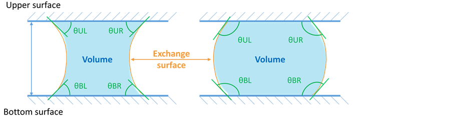
Figure 8. Evolution of different geometrical parameters (volume, exchange surface and contact angles.
![]()
Figure 9. Evolution of the volume and exchange area of the liquid bridges as a funtion of time, from 303 K to 343 K at a fixed liquid bridge height of 0.5 mm and a relative humidity of 55%: (a) silicon wafer substrates (results from [11] ); (b) PTFE substrates; (c) organosiloxane gel subtrates; (d) polymer coated substrates.
the same initial volume. It is worth mentioning that the initial surface of a perfect spherical drop of 4 μL is 12.19 mm2, while here in the case of a 0.5 mm height liquid bridge with an initial volume of 4 μL, the exchange surface with the drying air is around 5 - 6 mm2, whatever the temperature is. For the same initial volume, the exchange surface is more important in the case of the silicon wafer and the super hydrophobic coating (Figure 9(a) and Figure 9(d)), where the respective concave and convex shapes present an important curvature and give an initial value around 6 mm2. For PTFE and organosiloxane substrates, the exchange surface is less curved, which explains why the initial surfaces are between 5 and 5.7 mm2. In the case of silicon wafer, PTFE and organosiloxane gel (Figures 9(a)-(c)), the breaking of the liquid bridges occurs when the exchange surface is around 1 mm2, while the breaking point exchange surfaces for the super hydrophobic coating (Figure 9(d)) are higher (>2 mm2). This is due to the formation of a droplet which still presents a hydrophobic state between the two substrates.
These different variations are dictated by the nature of the contact between the substrates and the liquid. In order to gain a better understanding of the drying behavior, the observed contact angles were measured. The results are the subject of the following section.
3.3. Contact Angle Evolution
From image acquisition, the four contact angles of each observed liquid bridge were evaluated by image analysis. Compared to the hysteresis study presented in the first part, here the liquid bridge is compressed to a height value of 0.5 mm. When evaporating, the liquid bridge volume decreases and according to the wettability of the contact, it can be more and more in tension, which is similar to the stretching stage previously described. The results between silicon wafers come from a previous study and are presented in Figure 10. In a first step, from the initial values usually between 20˚ and 40˚, contact angles slightly decrease. Then, when the liquid bridges become unstable and are about to break, the contact angles decrease drastically. The behavior does not change with temperature. One of the four contact angles may present a different evolution compared to the others, due to the pinning of the contact line around the observed region, as noticed for the liquid bridge evaporation at 313 K. This reveals a local change of the surface state.
The results obtained on PTFE substrates are presented in Figure 11. Initial contact angles values are usually between 60˚ and 80˚. Whatever the temperature is, the behavior is unchanged. Unlike the silicon wafer substrates, the four contact angles decrease during all the drying process.
![]()
Figure 10. Evolution of the four contact angles of liquid bridges between two plates of silicon wafer, from 303 K up to 343 K at fixed relative humidity of 55% and a liquid bridge height of 0.5 mm.
![]()
Figure 11. Evolution of the four contact angles of liquid bridges between two plates of PTFE, from 303 K up to 343 K at fixed relative humidity of 55% and a liquid bridge height of 0.5 mm.
The same behavior is observed in the case of organosiloxane gel substrates (Figure 12), from initial contact angles values around 100˚ to the separation values under contact angles values of 50˚.
This decrease in contact angle is reflected by the change of curvature of the deionized water liquid bridge through the drying stage, where the exchange surface evolves from a convex shape to a concave shape, as illustrated in Figure 13 in the case of organosiloxane gel substrates at a temperature of 323 K and a fixed relative humidity of 55%.
The results obtained on super hydrophobic substrates in Figure 14. Initial contact angles values are usually between 130˚ and 150˚. Between two superhydrophobic plates, the contact angles almost do not vary and the wettability conditions stays hydrophobic, except at the very end of the liquid bridge existence where a slight decrease is observed before creating a unique residual sessile drop on one of the two surfaces, contrary to the other three substrates. However, at
![]()
Figure 12. Evolution of the four contact angles of liquid bridges between two plates of organosiloxane gel, from 303 K up to 343 K at fixed relative humidity of 55% and a liquid bridge height of 0.5 mm.
![]()
Figure 13. Evolution of curvature of a 0.5 mm height deionized water bridge between two plates of organosiloxane gel, at a temperature of 323 K and a relative humidity of 55%.
![]()
Figure 14. Evolution of the four contact angles of liquid bridges between two plates of superhydrophobic coating, from 303 K up to 343 K at fixed relative humidity of 55% and a liquid bridge height of 0.5 mm.
the temperatures of 303 K and 313 K, one of the four contact angles has a different evolution. The authors link this observation to the temperatures at which the measurements are realized. Indeed, at low drying temperatures such as 303 K and 313 K, volume variations are reduced, thus the evaporation front is slowly progressing. Consequently, the friction on the two surfaces is more important, and more time is left to the liquid to create a pinning of the contact line and a greater affinity with the two substrates. This behavior does not appear at the temperatures of 313, 323 and 333 K. Besides, in this particular case of a super hydrophobic contact, no change in curvature is observed during drying.
Generally, a change of curvature during drying occurs for the substrates with the largest gaps when realizing the hysteresis study, according to Figure 6. The liquid develops a greater affinity with the substrates for these surfaces, which leads to suggest that these particular evolutions are not necessary due to the rugosity but mostly to their surface chemistry.
4. Research Interest and Future Work
This study points out that even in the particular case of hydrophobic contact, a higher affinity for those particular substrates will lead to more hydrophilic contacts. Thus, capillary forces appear during drying, resulting in the change of curvature of the liquid/air interface. This could be related to a change in surface chemistry. This hypothesis, as well as the modification of the surface adhesion are currently being studied. These considerations are the subject of an increasing number of studies [14] [15] [16] [17] [18] . Accurate representations of the liquid behavior during evaporation in confined spaces is a topical issue. However, we noticed a lack of effective data to propose innovative models. Recently, modeling methods allowed realistic representation of liquids, whether in the case of modeling a liquid in contact with a substrate or just the liquid behavior [19] [20] . Yet, there is still no general approach to reproduce all the effects due to the interaction between the liquid and the air or the substrate. This study is part of a project which aims at providing data for these new innovative models.
5. Conclusion
Using a specific device to create liquid bridges within a humid environment and between hydrophobic surfaces, values of geometrical parameters, namely the volume, the exchange surface and contact angles of liquid bridges as a function of the drying time have been evaluated for temperatures from 303 to 343 K and a fixed relative humidity of 55%. Drying time decreases when temperature increases. The measurement of the four contact angles at a given time reveals that they don’t always follow the same trend, due to different substrate surface states. More precisely, a change of curvature is observed in the case of hydrophobic substrates. This suggests that even in the case of a liquid contained between locally hydrophobic regions, an affinity or a pinning can occur during drying, leading to classic concave menisci shapes observed in the case of hydrophilic contacts. Finally, the proposed study aims at providing new data for innovative models close to real cases, such as liquid flows and liquid evaporation in the particular case of hydrophobic materials.
Acknowledgements
The authors gratefully acknowledge the financial support provided by the Limousin region as part of the PhD of Etienne Portuguez.
Cite this paper
Portuguez, E., Alzina, A., Michaud, P., Hourlier, D. and Smith, A. (2017) Study of the Contact and the Evaporation Kinetics of a Thin Water Liquid Bridge between Two Hydrophobic Plates. Advances in Materials Physics and Chemistry, 7, 99-112. https://doi.org/10.4236/ampc.2017.74009
References
- 1. De Gennes, P.-G., Brochard-Wyart, F. and Quéré, D. (2004) Capillarity and Wetting Phenomena-Drops, Bubbles, Pearls, Waves. Springer-Verlag, New York.
https://doi.org/10.1007/978-0-387-21656-0 - 2. Erbil, H.Y. (2006) Surface Chemistry of Solid and Liquid Interfaces. Blackwell Publishing, Oxford.
- 3. Richards, L.A. (1931) Capillary Conduction of Liquids through Porous Mediums. Journal of Applied Physics, 1, 318-333.
https://doi.org/10.1063/1.1745010 - 4. Deegan, R.D., Bakajin, O., Dupont, T.F., Huber, G., Nagel, S.R. and Witten, T.A. (1997) Capillary Flow as the Cause of Ring Stains from Dried Liquid Drops. Nature, 389, 827-829.
https://doi.org/10.1038/39827 - 5. Quéré, D. and Reyssat, M. (2008) Non-Adhesive Lotus and Other Hydrophobic Materials. Philosophical Transactions of the Royal Society of London A: Mathematical, Physical and Engineering Sciences, 366, 1539-1556.
https://doi.org/10.1098/rsta.2007.2171 - 6. Feng, L., Li, S., Li, Y., Li, H., Zhang, L., Zhai, J., Song, Y., Liu, B., Jiang, L. and Zhu, D. (2002) Super-Hydrophobic Surfaces: From Natural to Artificial. Advanced Materials, 14, 1857-1860.
https://doi.org/10.1002/adma.200290020 - 7. Dash, S. and Garimella, S.V. (2014) Droplet Evaporation on Heated Hydrophobic and Superhydrophobic Surfaces. Physical Review E, 89, Article ID: 042402.
https://doi.org/10.1103/physreve.89.042402 - 8. Vargaftik, N.B., Volkov, B.N. and Voljak, L.D. (1983) International Tables of the Surface Tension of Water. Journal of Physical and Chemical Reference Data, 12, 817-820.
https://doi.org/10.1063/1.555688 - 9. Pérez-Díaz, J.L., álvarez-Valenzuela, M.A. and García-Prada, J.C. (2012) The Effect of the Partial Pressure of Water Vapor on the Surface Tension of the liquid Water-Air Interface. Journal of Colloid and Interface Science, 381, 180-182.
- 10. Portuguez, E., Alzina, A., Michaud, P., Oudjedi, M. and Smith, A. (2017) Evolution of a Water Pendant Droplet: Effect of Temperature and Relative Humidity. Natural Science, 9, 1-20.
- 11. Portuguez, E., Alzina, A., Michaud, P. and Smith, A. (2016) Evaporation Kinetics and Breaking of a Thin Water Liquid Bridge between Two Plates of Silicon Wafer. Advances in Materials Physics and Chemistry, 6, 157-166.
https://doi.org/10.4236/ampc.2016.67017 - 12. Qian, B. and Breuer, K.S. (2011) The Motion, Stability and Breakup of a Stretching Liquid Bridge with a Receding Contact Line. Journal of Fluid Mechanics, 666, 554-572.
https://doi.org/10.1017/S0022112010004611 - 13. Chen, H., Amirfazli, A. and Tang, T. (2013) Modeling Liquid Bridge between Surfaces with Contact Angle Hysteresis. Langmuir, 29, 3310-3319.
https://doi.org/10.1021/la304870h - 14. Bormashenko, E.Y. (2013) Wetting of Real Surfaces. Walter de Gruyter.
https://doi.org/10.1515/9783110258790 - 15. Mielniczuk, B., Hueckel, T. and El Youssoufi, M.S. (2014) Evaporation-Induced Evolution of the Capillary Force between Two Grains. Granular Matter, 16, 815-828.
https://doi.org/10.1007/s10035-014-0512-6 - 16. Rabinovich, Y.I., Esayanur, M.S. and Moudgil, B.M. (2005) Capillary Forces between Two Spheres with a Fixed Volume Liquid Bridge: Theory and Experiment. Langmuir, 21, 10992-10997.
https://doi.org/10.1021/la0517639 - 17. Zhou, Z., Li, Q. and Zhao, X.S. (2006) Evolution of Interparticle Capillary Forces during Drying of Colloidal Crystals. Langmuir, 22, 3692-3697.
https://doi.org/10.1021/la052934c - 18. Butt, H.J. (2008) Capillary Forces: Influence of Roughness and Heterogeneity. Langmuir, 24, 4715-4721.
https://doi.org/10.1021/la703640f - 19. Tartakovsky, A. and Meakin, P. (2005) Modeling of Surface Tension and Contact Angles with Smoothed Particle Hydrodynamics. Physical Review E, 72, Article ID: 206301.
https://doi.org/10.1103/physreve.72.026301 - 20. Akinci, N., Akinci, G. and Teschner, M. (2013) Versatile Surface Tension and Adhesion for SPH Fluids. ACM Transactions on Graphics, 32, Article No. 182.
https://doi.org/10.1145/2508363.2508395