Open Journal of Safety Science and Technology
Vol.4 No.2(2014), Article
ID:46603,11
pages
DOI:10.4236/ojsst.2014.42009
Assessment of Head Injury Criterion Score of Shock Attenuation Material Employed around Playground Equipment Using Nonlinear Spring Contact Model
Yuji Ohue1*, Keita Miyoshi2
1Faculty of Engineering, Kagawa University, Takamatsu, Japan
2Graduate School of Engineering, Kagawa University, Takamatsu, Japan
Email: *ohue@eng.kagawa-u.ac.jp
Copyright © 2014 by authors and Scientific Research Publishing Inc.
This work is licensed under the Creative Commons Attribution International License (CC BY).
http://creativecommons.org/licenses/by/4.0/


Received 28 February 2014; revised 28 April 2014; accepted 12 May 2014
ABSTRACT
In order to investigate the influence factors on HIC (Head Injury Criterion) score of shock attenuation materials employed around playground, impact tests were carried out in accordance with ASTM standard. Four kinds of the commercial shock attenuation materials were employed for the test. The apparatus is composed of the missile made from aluminum alloy with a mass of 4.6 kg and a tri-axial accelerometer. The higher the missile was dropped, the more HIC score increased. The HIC score depended on the peak deceleration in collision. From the time-frequency analysis, it was obvious that HIC score depended on the characteristic frequency of the vibration system in collision between the missile and the shock attenuation material. There was sufficient evidence to suggest that the use of a simple vibration system with a nonlinear hardening spring is beneficial to assess HIC score and peak deceleration for the shock attenuation material.
Keywords:HIC, Playground, Shock Attenuation Material, Collision, Nonlinear Spring Contact Vibration Model, Wavelet Transform

1. Introduction
Fall injuries in playground are a significant public health issue resulting in traumatic experiences for children and substantial medical costs for the community [1] -[3] . Height of equipment from which children fall, and the playground surfacing onto which they land are two important risk factors for playground injury. Figure 1 shows the chronological table of safety criteria for playground equipment in industrially advanced nations. In European Union and United States of America, the safety criteria for playground equipment have been standardized from 1998. The safety criteria for playground equipment in Japan were established 4 years later. Intracranial injuries due to fall, which comprise almost 60% of playground injuries in Japan, represent most of the now rare fatal playground injuries [3] . From 2008, current playground standards in Japan recommend a peak deceleration gmax less than or equal to 200 G, which corresponds to 200 times of the acceleration of gravity g, and a maximum head injury criterion (HIC) score less than or equal to 1000 to prevent severe head injury. The two factors HIC score and gmax are defined in ASTM F1292 or EN 1176 and 1177 in 1998. JPFA (Japan Park Facilities Association) has adopted ASTM F1292 to evaluate the above mentioned two factors. Those factors are measured by an instrument including hemispherical missile attached tri-axial accelerometer, and are calculated from deceleration during collision between the missile and surfaces by software.
Several previous studies which were based on shock attenuation of playground surfaces have been reported [4] -[6] . These papers employed wood mulch, wood chip, sand, gravel, grass sod and rubber for the surfaces to attenuate the shock of fall. Ramsey et al. investigated a several playground surfacing materials including manufactured mats, asphalt and concrete to determine their shock absorbing properties [4] . Bullen et al. reported the safe fall heights for surface materials under dry and wet conditions. Mack et al. found that shock attenuation of several surface materials improved as surface depth of the materials was increased. From these studies, rubber was superior to wood chips and so forth. However, those papers have not discussed the relationship between mechanical properties of rubber and HIC score. Usually, the shock attenuation material made from rubber chips has been produced by small companies. The companies do not have enough funds to prepare for the instrument of the HIC test to assess the shock attenuation material, since the tri-axial accelerometer and the software including the instrument are expensive. While, a static mechanical property of the shock attenuation material such as a relationship between applied force using dead weight and displacement due to deformation is measured at lower cost. Assessing the dynamic HIC score by the static mechanical property of the shock attenuation material enables the small companies to develop and design new shock attenuation material at low cost.
Therefore, the above mentioned factors HIC and gmax require discussing the collision behavior on the playground surfacing in view of dynamic and tribological contacts. In this study, in order to estimate the HIC (Head Injury Criterion) score of the shock attenuation materials employed for playground, impact tests were carried out and a vibration system with a nonlinear hardening spring was discussed to assess HIC score and the peak deceleration value. The method which evaluates HIC score of the shock attenuation material made from rubber chips relatively using a universal testing machine with a hemisphere indenter was proposed.
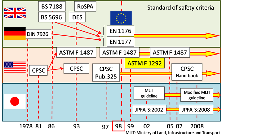
Figure 1. Chronological table of safety criteria for playground equipment.
2. Experimental Method on HIC
Four kinds of the shock attenuation materials made of rubber chips were prepared from a routine commercial lot to investigate the HIC performance of the materials. Figure 2 shows the surface, the side and the back of each shock attenuation material. The shock attenuation materials were bilaminate surfaces comprising a top layer of fine rubber granules and a bottom layer of large shredded rubber particles. The materials had a square shape with each side being 500 mm long. The notations of the materials were defined as J110, J75, J50, C50 corresponding to the thickness of the material. The head characters “J” and “C” of the notations express the difference on the kind of the rubber particle.
Current playground standards conforming to ASTM F1292 recommend a maximum HIC score less than or equal to 1000 and a peak deceleration value less than or equal to 200 G to prevent severe head injury. The standard ASTM F1292 comes from the study by McElhaney [7] . Figure 3 shows the measuring system of HIC score in this experiment. HIC score and peak deceleration gmax corresponding to free-falls from drop heights of 0.5 m to 1.2 m were measured using a standard missile. The missile made of aluminum alloy 6061-T6 has a hemis-
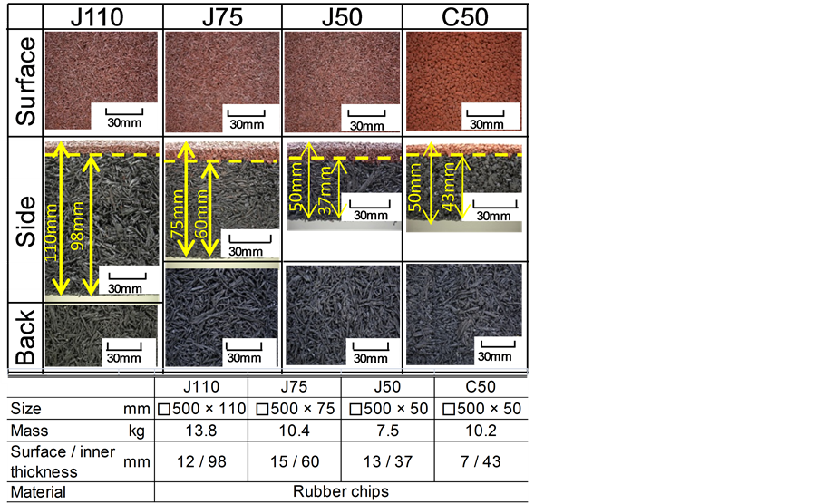
Figure 2. Specifications of shock attenuation materials made from rubber chips.
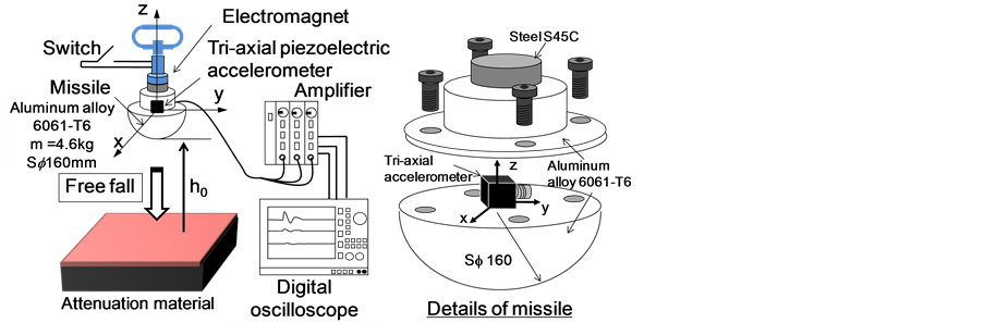
Figure 3. Apparatus and method for HIC measurement.
phere shape with a diameter of 160 mm and a mass of 4.6 kg. The tri-axial accelerometer was attached to the center position on the flat of the missile. The missile can be dropped from a predetermined height h0 to the shock attenuation material using a switch with electromagnet. The acceleration data during the collision between the missile with free fall and the material were stored using a digital oscilloscope through an amplifier.
Figure 4 shows an example of acceleration waves. The acceleration waves a obtained by tri-axial accelerometer were divided by the acceleration of gravity g as shown in Equation (1). The composition acceleration AR was calculated by Equation (2). After that, HIC score was calculated by Equation (3) conforming to ASTM F1292. The peak deceleration gmax was defined as the maximum of wave AR.
 (1)
(1)
 (2)
(2)
 (3)
(3)
where, ax, ay and az (m/s2) are accelerations in each direction, and subscript character z indicates the vertical direction of the flat surface of the missile. Ax, Ay and Az (G) are accelerations denoted by the standard of the acceleration of gravity g (9.81 m/s2). HIC intervals t1 – t0 (s) is defined as time span, when HIC score becomes maximum. The Equation (3) shown in the standard ASTM F1292 comes from the study by McElhaney [7] .
3. HIC Score and gmax of Shock Attenuation Material
Figure 5 shows the relationship between drop height h0 and HIC score. When the missile is dropped from h0 = 1.2 m, the impact velocity of the missile on the shock attenuation material reaches 4.9 m/s since the potential energy of the missile is 54.2 J. The higher the missile was dropped, the more HIC score increased. The increase in thickness of the material brought about the decrease in HIC score. Comparing J50 with C50, HIC score of J50 was less than that of C50, since the rubber type of J50 was different from that of C50.
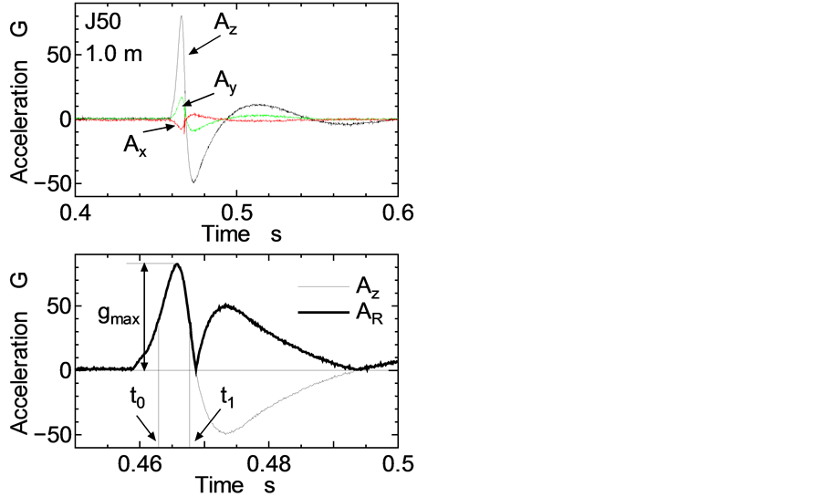
Figure 4. Acceleration waves and composition wave in collision.
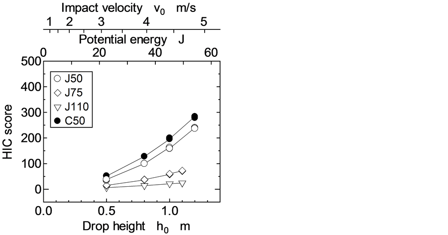
Figure 5. Relationship between HIC score and drop height.
Figure 6 shows the relationship between drop height h0 and coefficient of restitution e given by Equation (4).
 (4)
(4)
where, h1 is maximum bounce height and was measured by a motion analysis using a video camera. The e was independent of the drop height and the thickness of the material in the case of same rubber chips. While, the e was affected by the rubber type since e of J50 was larger than that of C50. This result shows that the potential energy of the missile due to free-fall was consumed at a shallow depth below the surface of the shock attenuation material during the collision, and the depth was independent of the thickness of the shock attenuation material.
Figure 7 shows the relationship between HIC score and gmax. In this experiment, gmax was directly proportional to HIC score according to the expression shown in Figure 7. Therefore, HIC score can be evaluated using gmax. Furthermore, HIC score was not determined by energy absorption in collision between the missile and the material, since the coefficient of restitution was constant in spite of drop height from the results shown in Figures 5-7.
In order to investigate the dynamic performance in collision between the missile and the material, the acceleration wave Az in the direction of free fall was analyzed by time-frequency analysis using wavelet transform (WT) [8] -[10] . WT is given by Equation (5).
 (5)
(5)
where,  is mother wavelet function,
  is complex conjugate of
 , a and b are time and frequency parameters, respectively. Gabor function was adopted as
  in this calculation [8] -[10] .
Figure 8 shows the waves Az and its time-frequency analysis in the case of J75 under three drop heights, which are of (a) h0 = 0.5 m, (b) h0 = 0.8 m and (c) h0 = 1.0 m. The peak intensity in time-frequency domain changed during the collision between the missile and the shock attenuation material. The peak intensity after the collision converged at the frequency fmn = 15 Hz, which is the natural frequency of the missile calculated by finite element analysis, for any drop heights and any kinds of the shock attenuation material. The frequency fn at maximum intensity was adopted as the characteristic one in the collision as shown in Figure 8(d). The intensity in time-frequency domain became maximum the moment the amplitude of the wave Az indicated maximum.
Figure 9 shows the relationship between the frequency fn and the drop height h0. The frequency fn increased
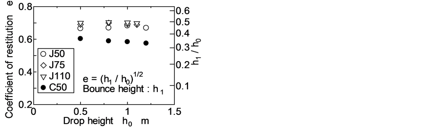
Figure 6. Relationship between coefficient of restitution and drop height.
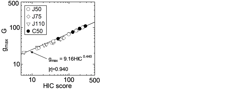
Figure 7. Relationship between HIC score and gmax.
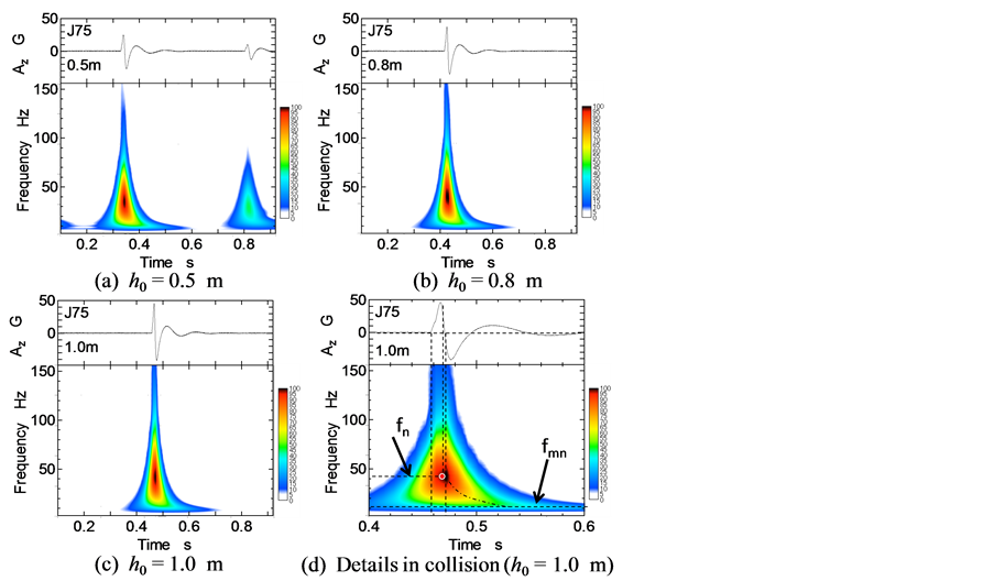
Figure 8. Time-frequency analysis of impact wave by wavelet transform.
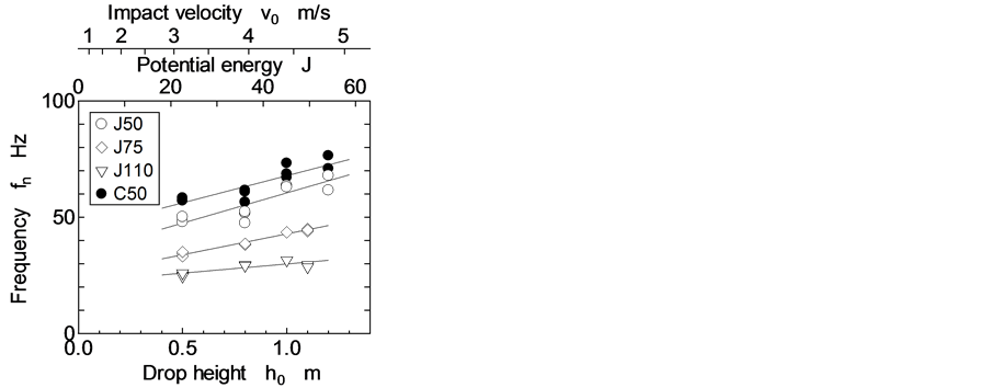
Figure 9. Change in characteristic frequency in collision.
as the drop height became higher. The slope of the relationship between fn and h0 gradually decreased as the thickness of the shock attenuation material became thicker. Although the slope of J50 was almost the same as that of C50, the value of fn was different from each other due to the rubber type.
Figure 10 shows the relationship between the HIC score and the frequency fn. The frequency fn was directly proportional to the HIC score. Furthermore, The fn was also proportional to gmax, since the HIC score was proportional to gmax as shown in Figure 7. Therefore, it is obvious that the HIC score and gmax depend on the frequency fn, which is one of the dynamic characteristics in collision between the missile and the shock attenuation material.
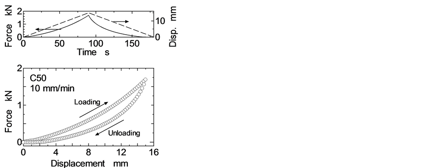
In order to discuss the collision between the missile and the shock attenuation material, the static stiffness of the material was measured using a universal testing machine employed for the missile (hemisphere indenter), which is the same as one used for HIC test. Figure 11 shows the relationship between displacement and force in the case of C50. The material was loaded by the missile with a loading speed of 10 mm/min, since the HIC score and gmax was obtained by the collision of the missile and the shock attenuation material in this experiment. The path on the stiffness of the material between loading and unloading was different from each other as shown in Figure 11(a). For both loading and unloading, the relationship between the loading force F and the displacement z on a graph of a logarithmic scale obeyed each power law given by Equation (6).
 (6)
(6)
where, k (N/mn) and n are the stiffness constant and the slope of a relationship between F and z on a graph of a logarithmic scale, respectively.
Figure 12 shows the relationship between the thickness of the shock attenuation material and both k and n. When a spherical body contacts with a flat surface, which have elasticity, the slope n of the relationship between F and z on a graph of a logarithmic scale becomes 1.5 according to Hertzian elastic contact theory. However, the slope n became larger than 1.5 for unloading, since the shock attenuation materials made from rubber ships have viscoelasticity. Both parameters k and n were smaller as the thickness of the shock attenuation material became thicker. The parameters k and n of J50 were slightly smaller than those of C50. The frequency fn occurred during unloading in collision as shown in Figure 8(d). Therefore, the dynamic performance in collision is dependent of the stiffness in unloading.
4. Assessment of HIC Score and gmax Using Vibration System with Nonlinear Spring
From the results shown in Figures 10-12, the dynamic behavior of the collision between the missile and the shock attenuation material depended on the frequency fn. The impact velocity of the missile brought about the change in the frequency fn. Furthermore, the stiffness of the shock attenuation material had the characteristics of nonlinear hardening spring. The stiffness showed the static load-displacement curve for a nonlinearly hardening spring. Therefore, the free vibration of an undamped system with a nonlinearly elastic spring in collision is
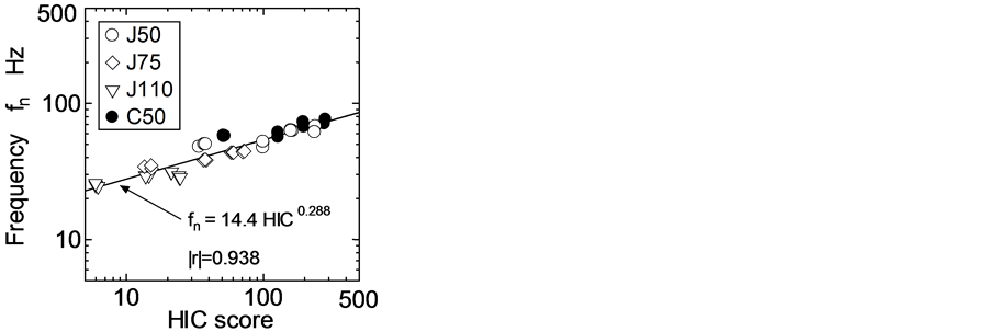
Figure 10. Relationship between HIC score and characteristic frequency in collision.
 (a)
(a) (b)
(b)
Figure 11. Relation between force and displacement using universal testing machine employed for missile, (a) Force and displacement; (b) Force and displacement plotted on log-log graph.
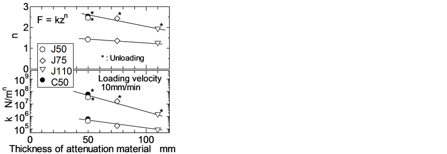
Figure 12. Characteristics of nonlinear spring of shock attenuation materials.
adopted as shown in Figure 13. The equation of motion in collision of the situation from (a) to (d) as shown in Figure 13 in this study was defined as Equation (7) [11] .
 (7)
(7)
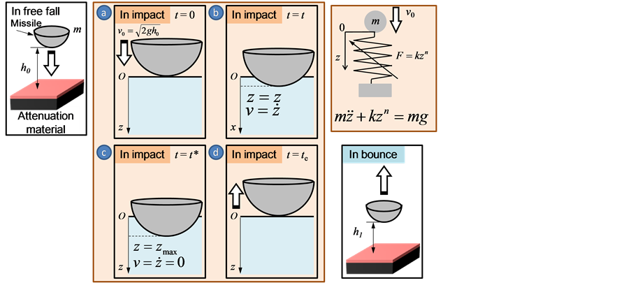
Figure 13. Model for contact vibration system using nonlinear hardening spring.
where, m is mass of the missile, k and n are stiffness and its power of the material obtained by universal testing machine as shown in Figure 12, respectively. Expressing the acceleration  in Equation (7) as the derivative of the velocity
 , Equation (7) is modified as the following.
 (8)
(8)
Equation (8) is integrated from z = 0 to z = zmax to obtain kinematic energy up to  at z = zmax where gmax becomes maximum.
 (9)
(9)
Assuming that the potential energy mgzmax during the collision is ignored since mgzmax during the collision is too smaller than that at initial drop height of the missile and that the velocity of the missile corresponding to zmax in an extreme position is zero. Substituting  at z = 0 and
  at z = zmax into the result on the integration of Equation (9), zmax is given by Equation (10). From Equations (7) and (10), gmax is given by Equation (11).
 (10)
(10)
 (11)
(11)
Equation (11) enables to calculate gmax from initial velocity v0 of the missile due to drop height and the parameters k and n of a nonlinearly hardening spring of the shock attenuation material expressed by Equation (7), and to estimate HIC score from gmax as shown in Figure 7.
Figure 14 shows the change in estimated gmax and the experimental one against the impact velocity v0. The estimated values were larger than the experimental ones, since the proposed vibration model did not include any damping terms. However, the tendency of the estimations (thick lines) against v0 agreed almost with that of the experiments (marks), although the estimated values were calculated by the proposed model without any damping terms. Especially, although the parameters k and n of the spring for J50 were slightly less than those for C50, the proposed model enabled to assess the slight difference in gmax between J50 and C50. Therefore, there was sufficient evidence to suggest that the use of a simple vibration system with a nonlinearly hardening spring as
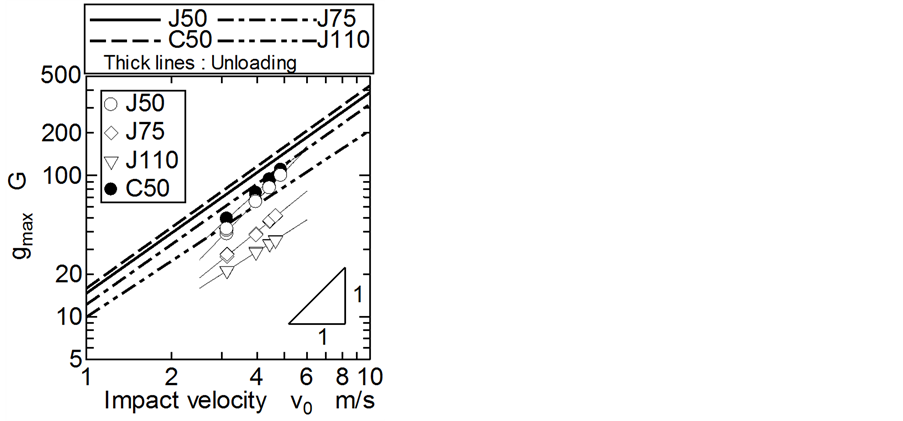
Figure 14. Assessment of and gmax using vibration system with nonlinear hardening spring.
given by Equation (7) is beneficial to assess HIC score for the shock attenuation materials relatively, since HIC score can be evaluated using gmax as shown in Figure 7.
5. Conclusions
In order to estimate the HIC (Head Injury Criterion) score of shock attenuation materials used for playground, impact tests were carried out. Peak deceleration gmax and HIC score corresponding to free-falls from drop heights of 0.5 m to 1.2 m were measured using a standard missile, conforming to ASTM F1292. The obtained results are summarized as follows:
1) The higher the missile was dropped, the more HIC score increased. The HIC score depended on the peak deceleration gmax in collision.
2) From the time-frequency analysis, it was obvious that HIC score depended on the natural frequency of the vibration system in collision between the missile and the shock attenuation material.
3) The static stiffness of the shock attenuation material was measured using a universal testing machine employed for the missile, which is the same as one used for HIC test. The stiffness was smaller as the thickness of the shock attenuation material became thicker.
4) The estimated values obtained by the vibration model with nonlinear hardening spring were larger than the experimental ones, since the proposed vibration model did not include any damping terms. However, the tendency of the estimations agreed almost with that of the experiments, although the estimated values were calculated by the proposed model without any damping terms. Therefore, there was sufficient evidence to suggest that the use of a simple vibration system with a nonlinear hardening spring is beneficial to assess peak deceleration and HIC score for the shock attenuation materials. Furthermore, assessing HIC score by the static mechanical property enables to develop and design new shock attenuation material at low cost.
Acknowledgements
The authors are very grateful to Tsumura Co., Ltd. for providing shock attenuation materials and their encouragement.
References
- Altman, A., Ashby, K. and Stathakis, V. (1996) Childhood Injuries from Playground Equipment. Hazard, 29, 1-13.
- Macarthur, C., Hu, X., Wesson, D.E., et al. (2000) Risk Factors for Severe Injuries Associated with Falls from Playground Equipment. Accident Analysis & Prevention, 32, 377-382. http://dx.doi.org/10.1016/S0001-4575(99)00079-2
- Japanese Ministry of Health, Labour and Welfare (2001) Investigation Report of Accidents in Playground 2001. (In Japanese) http://www.mhlw.go.jp/houdou/0110/h1029-3.html
- Ramsey, L.F. and Preston, J.D. (1990) Impact Attenuation Performance of Playground Surfacing Materials. US Consumer Product Safety Commission, Washington, D.C.
- Bullen, F. and Jambunathan, J. (1991) The Design and Selection of Undersurfacing Systems for Children’s Recreational Areas, Australian Civil Engineering Transactions. The Institution of Engineers, CE33, 263-268.
- Mack, M.G., Sacks, J. and Thompson, D. (2000) Testing the Impact Attenuation of Loose-Fill Playground Surfaces. Injury Prevention, 6, 141-144. http://dx.doi.org/10.1136/ip.6.2.141
- McElhaney, J. (1976) Biomechanics—Head Injury Criteria. Polymer Mechanics, 12, 411-429.
- Mallat, S. (1998) A Wavelet Tour of Signal Processing. Academic Press, Cambridge.
- Ohue, Y., Kounou, T. and Yazama, K. (2011) Diagnosis on Pitting Failure in Gear Equipment Using Time—Frequency Domain Analysis. TRIBOLOGIA—Finnish Journal of Tribology, 30, 51-59.
- Ohue, Y. and Yoshida, A. (2003) New Evaluation Method on Gear Dynamics Using Continuous and Discrete Wavelet Transforms. ASME, Journal of Vibration and Acoustics, 125, 274-281.
- Weaver, W., Timoshenko, S.P. and Young, D.H. (1990) Vibration Problems in Engineering. 5th Edition, John Wiley & Sons, Hoboken, 139-221.
NOTES

*Corresponding author.