Open Journal of Safety Science and Technology
Vol.3 No.3(2013), Article ID:37085,8 pages DOI:10.4236/ojsst.2013.33005
Effect of Beam Length and Braced Length on Moment-Rotation Behavior of Castellated Beams
1Civil Engineering Department, Semnan University, Semnan, Iran
2Civil Engineering Department, Islamic Azad University, Fars Science and Research Branch, Shiraz, Iran
Email: Saberi.hamid@gmail.com
Copyright © 2013 Mohsen Gerami et al. This is an open access article distributed under the Creative Commons Attribution License, which permits unrestricted use, distribution, and reproduction in any medium, provided the original work is properly cited.
Received November 27, 2012; revised December 25, 2012; accepted January 8, 2013
Keywords: Castellated Beam; Finite Element Method; Rotational Capacity; Braced Length; Monotonic Loading; Numerical Modeling; Moment-Rotation Behavior
ABSTRACT
The presence of web openings in castellated beams introduces different modes of failure at the perforated sections such as excessive stresses in tee-sections, excessive stresses in mid-depth of the web post, web-post buckling, developing plastic Vierendeel mechanism. This paper presents nonlinear behavior of castellated beams under moment gradient loading and investigates the effect of beam length and braced length on moment-rotation behavior and ductility of this type of beams. Accuracy of finite element models of plain-webbed beams is evaluated comparing moment-rotation behavior and failure mode of other researchers’ numerical models and cleared a satisfactory accuracy. Rotational capacity of castellated beams, derived from numerical modeling, is compared with corresponding I-shaped plain-webbed steel beams and it is cleared that for the short beams, web openings reduce energy absorbance and plastic moment capacity of the beams more than long ones.
1. Introduction
Using castellated I-shaped steel beams as main girders in moment resisting frames necessitates to observe some seismic code provisions, which is together with some erection difficulties. However this type of beams has a vast application as simply supported gravity girders [1].
Web buckling failure mode of castellated beams under shear force is studied in [2] by R. Redwood and S. Demirdjian, testing four simply supported castellated beams with concentrated loads at beam mid length. The tests showed that the web buckling is depending on restraining effect of beam flanges and lateral torsional bracing of upper flange. A parallel parametric finite element modeling was done ignoring material nonlinearity and residual stresses. Elastic buckling modeling consume was based on the fact that due to sharp widening of the web post above and below the mid depth, shear and bending combination is unlikely yield inelastic buckling of web posts. Based on the results of 27 parametric models, a relationship between web posts horizontal shear capacity, which is depend on post geometry and its mechanical properties, and applied vertical load is determined and a procedure proposed to check the web post buckling failure mode of the simply supported beams subjected to uniformly distributed loads.
W. Zaarour and R. Redwood [3] have investigated the web post buckling failure mode on 12 simply supported castellated beams loaded at mid-span of the beam. Their study also contains finite element simulation of a web post and flanges adjacent to mid-span, using NASTRAN. Four sided shell element was used in finite element modeling considering material nonlinearity. Their study showed that the web post buckling is a potential failure mode and should be considered in design.
A. Mohebkhah [4] has studied the inelastic lateral torsional buckling of castellated beams subjected to concentrated and uniformly distributed loads using finite element method. First order shell43 element of ANSYS5.4 element library was used to model beam flanges and web. Results of numerical models were verified comparing with experimental data of Nethercot and Kedral tests. Results of parametric study showed that for analyzed models, the factor of Cb, proposed by AISC-LRFD to compute moment capacity of beams, is not accurate and so equations proposed to evaluate Cb factor for each case of loading.
Ductility of steel I-shaped beams under moment gradient and constant moment loading is studied for high strength steels [5-7]. In these studies several failure modes of the beam failure is extracted and categorized depend on the inherent imperfections of the beams.
In this paper a parametric study is done to investigate the moment-rotation behavior and ductility of castellated beams under moment gradient loading for different beam lengths using experiments data and finite element modeling.
2. Parametric Study
To investigate the rotational behavior of standard Iranian castellated beams with hexagonal openings, a parametric inelastic finite element model has been developed. Both the beam length and bracing length ratio were considered as parameter. The simply supported beams are investigated under moment-gradient loading applying concentrated load at the midpoint of it.
The results of castellated beam models are compared with corresponding traditional I-shaped steel beams with no web perforations, to have a better understanding of moment-rotation behavior of this type of beams. Since there were not available test results of plain-webbed steel beam, the FE models of these beams verified comparing with numerical models of other researchers.
2.1. Finite Element Models of Castellated Beams
A standard castellated beam, similar to the tested beams, CPE14 (d = 14, bf = 7.3, tf = 0.69, tw = 0.47 cm) is chosen to this study and its schematic form is shown in Figure 1. To have a comparison with plain-webbed beams behavior, the models loading and boundary conditions defined similar to the simply supported beam model of C. J. Earls [7], explained later.
Full depth 2.5 mm of thickness stiffeners are considered in both sides of web at beam tips and mid span.
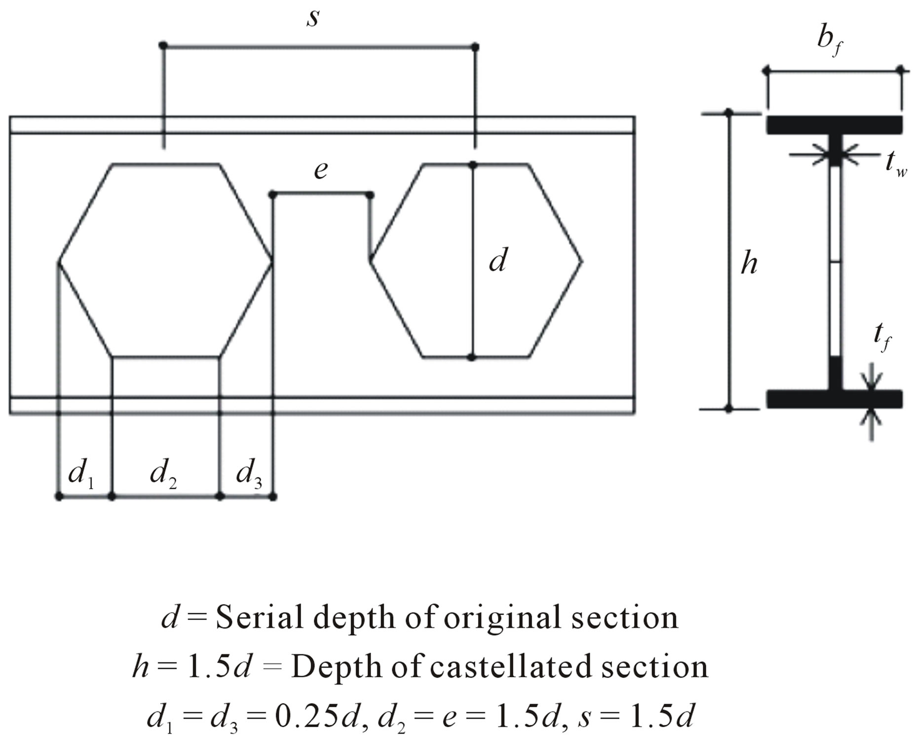
Figure 1. Castellated beam opening geometry [4].
Specimens named with SX which X dominates number of web opening and are listed in Table 1. Figure 2 shows FE modeling of specimens S8.
2.2. Loading Pattern and Boundary Conditions
To impose moment-gradient loading on finite element models, the simply supported specimens subjected to a concentrated load at mid span which yields a maximum moment of PL/4 at mid-span with linearly decrease up to zero at supports. Figure 3 shows loading pattern of models.
Two bracing conditions are considered in this study:
Case1: In this bracing condition all nodes in both supports and bottom flange nodes are restrained against out of web plane deformations. Specimens S14 and S18 have additional restrain at mid span under concentrated load.
Case2: This bracing condition has top flange nodes restrained against out of web plane deformation in addition with restrained nodes mentioned in case1.
2.3. Verification of Numerical Modeling
Since the results presented in this study are based on modeling and FE analysis using the ANSYS software, the ability of the software to predict the behavior of castellated beams should be examined by comparing the results with that of numerical and experimental results.
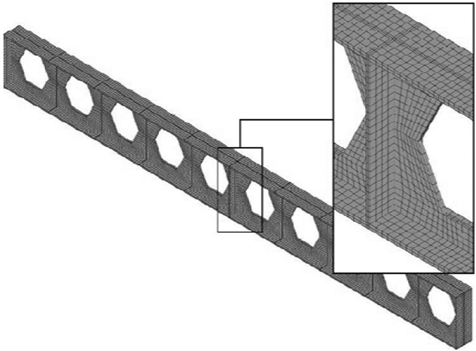
Figure 2. Finite element modeling and mesh pattern of model S8.
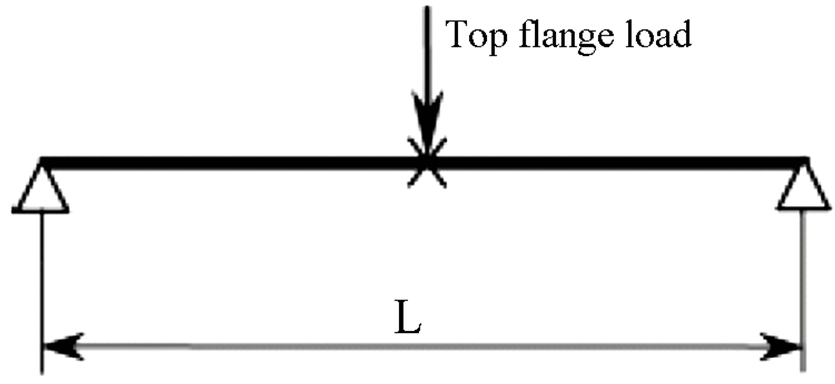
Figure 3. Loading of models.
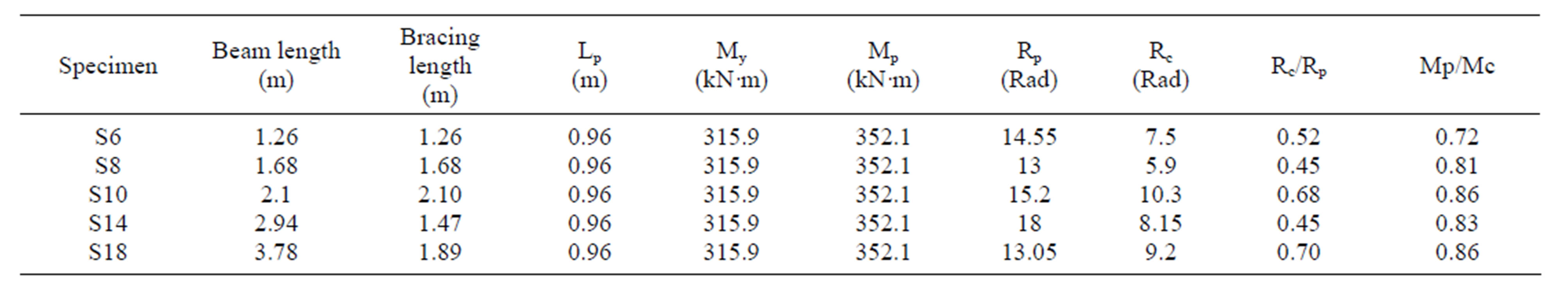
Table 1. General properties of specimens.
2.3.1. Verification of FE Modeling with Experimental Results
To evaluate the accuracy of FE models, the numerical results are compared with experimental results of Specimens tested by Saedi Daryan [8].
Two castellated beams are fabricated from hot-rolled IPE14 steel beams in 2 and 3 meter lengths. The specimens are welded to a relatively rigid stub column to make a cantilever configuration and are loaded monotonically on their tips. To remove undesirable possible failure modes such as connection weld fracture, full depth web plates and top-seat bracket plates are used to strengthening connection of the specimens. The stiffeners have just 10 cm weld on beam flange. Two specimens were restrained in 1meter far from the column stub edge. Figure 4 shows configuration of the specimen and its lateral support.
The specimens mentioned as “A” for 2 meter length beam and “B” for 3 meter. The yield stress of beam materials according to the tension test results is reported as 235 MPa with a 796 MPa at 15% strain.
The loading process is stopped accruing lateral torsional buckling of the specimens. The deflection of bottom flange in the adjacent of the lateral braces is measured.
The results of the tests are used to verify the results of later finite element models. Finite element modeling of specimens is done using general finite element software ANSYS 5.4 which has ability to consider both geometric and material nonlinearities in a given model (Figure 5). All beam flanges, web and stiffeners were modeled using first order eight node brick element, SOLID45, which can consider large stain and large deformation effects. Having two segments through the thickness of beam components, considering local buckling effects and local flexural deformation is possible. Beam flanges were modeled with four elements across the width. To avoid convergence difficulties raised from stress concentration at the corners of web openings, these regions were meshed more refined [9,10].
One of the important subjects that affect the accuracy and applicability of the FE modeling results is the proper definition of materials in nonlinear area. Consequently, steel is assumed to behave as an elasto-plastic material with strain hardening.
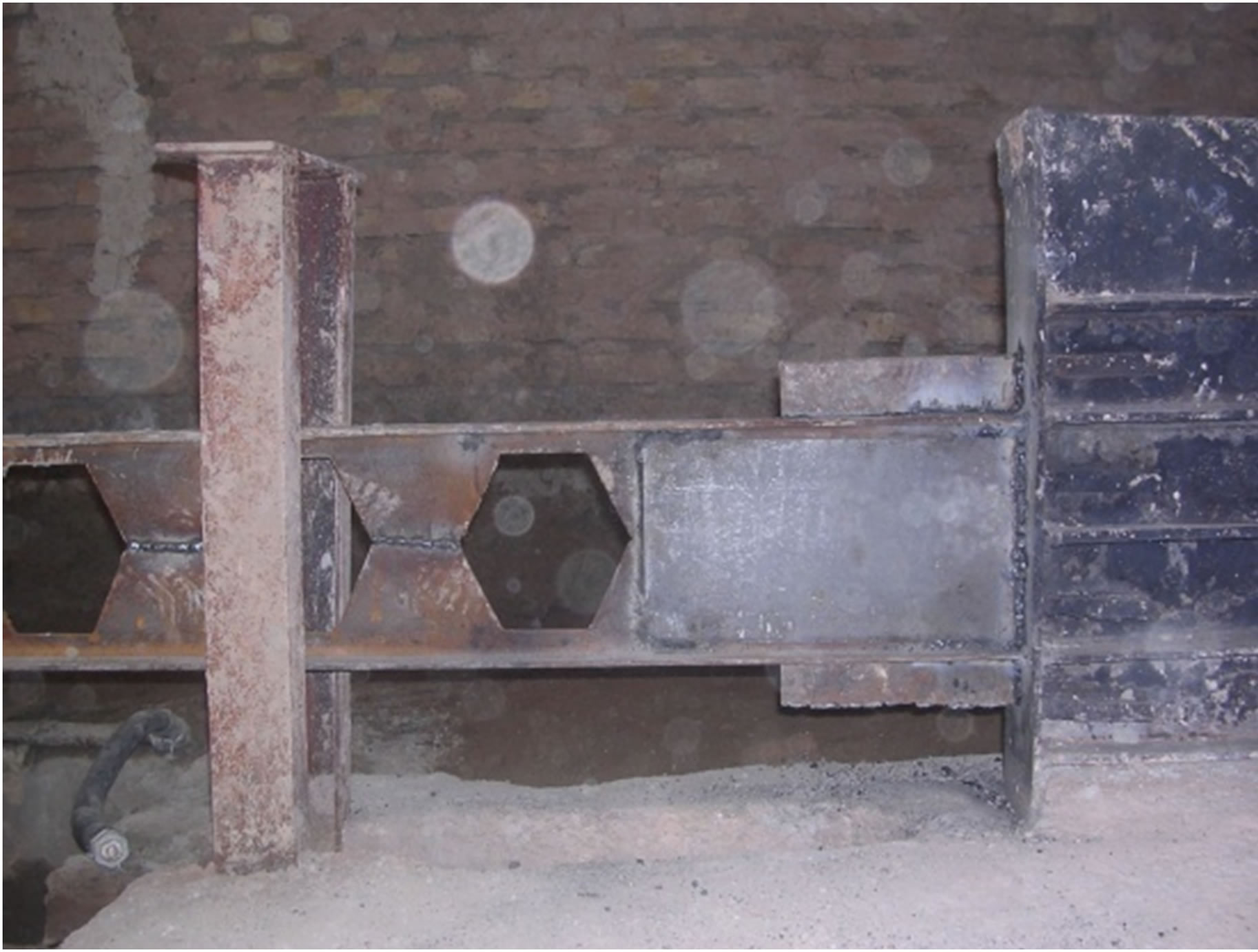
Figure 4. Experimental specimen “A” and its test setup.
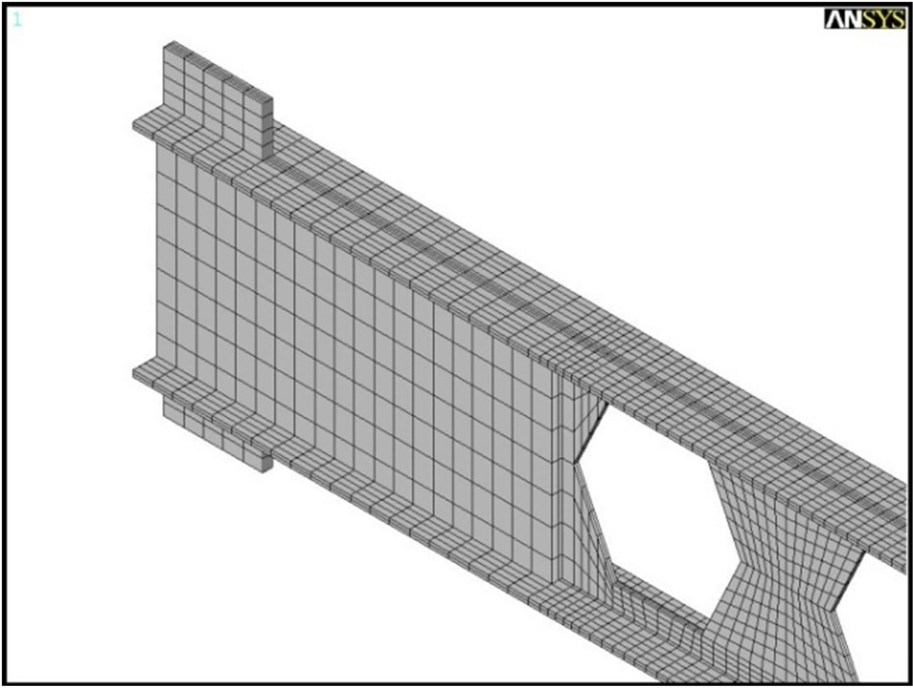
Figure 5. Finite element model of specimens.
Since the experimental tests showed that the final failure mode is lateral-torsional buckling, the required considerations should be accounted for in modeling and analysis; that is, an element should be used in a simulation that is capable of considering all geometrical nonlinearities including lateral-torsional buckling, and an initial defect is also considered in beam modeling. This initial defect is applied by a very slight displacement in out of plane direction imposed on the beam web to disturb the complete symmetry of the beam and provide the possibility of torsion in the beam.
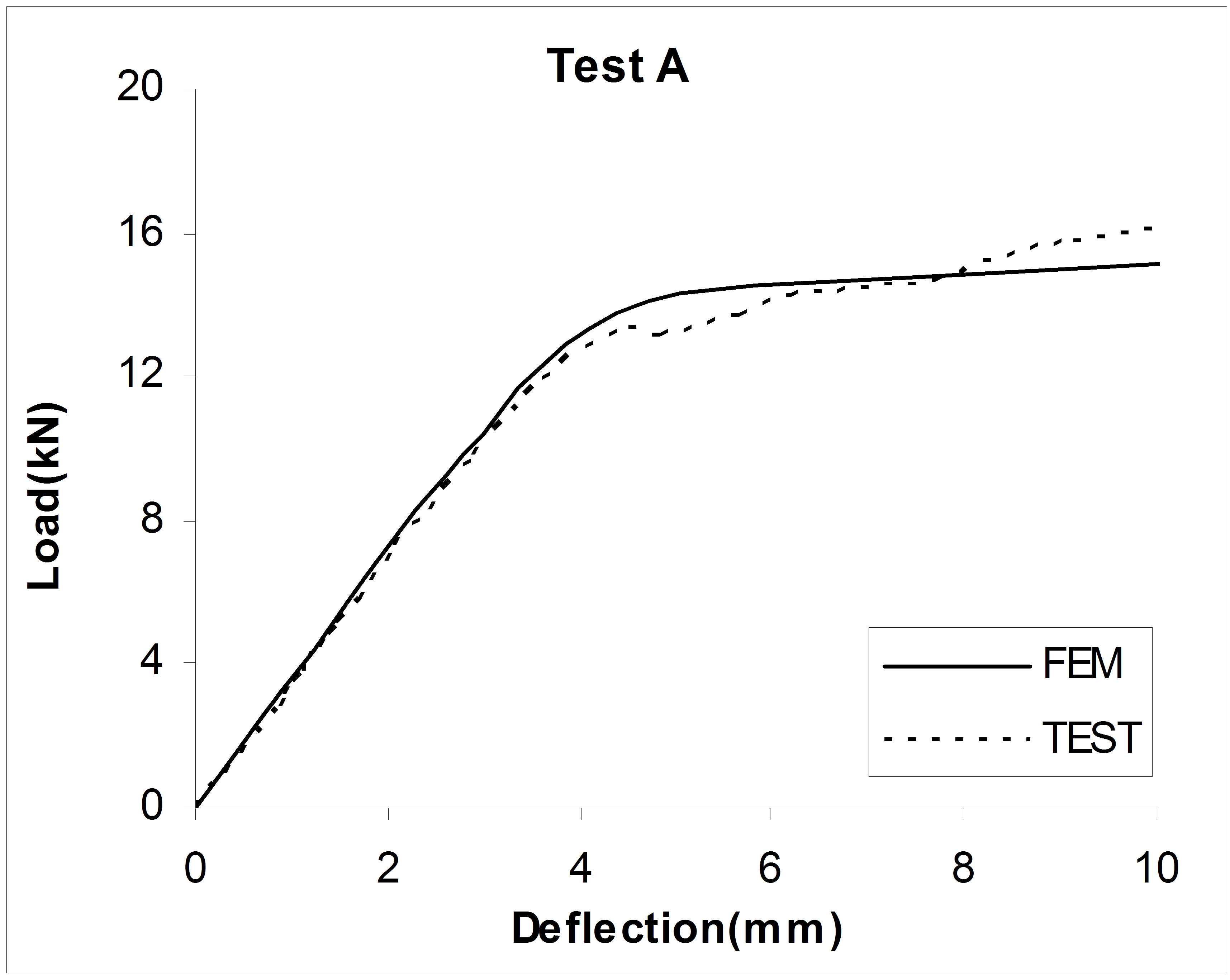
Load-deflection curves of the specimens are shown in Figure 6. From the figures, finite element model and test results have a good agreement in linear range but in nonlinear range numerical modeling overestimates beam strength.
Both specimens had lateral torsional buckling mode. Final state of specimen “B” is shown in Figure 7.
2.3.2. Verification of FE Modeling with Numerical Results
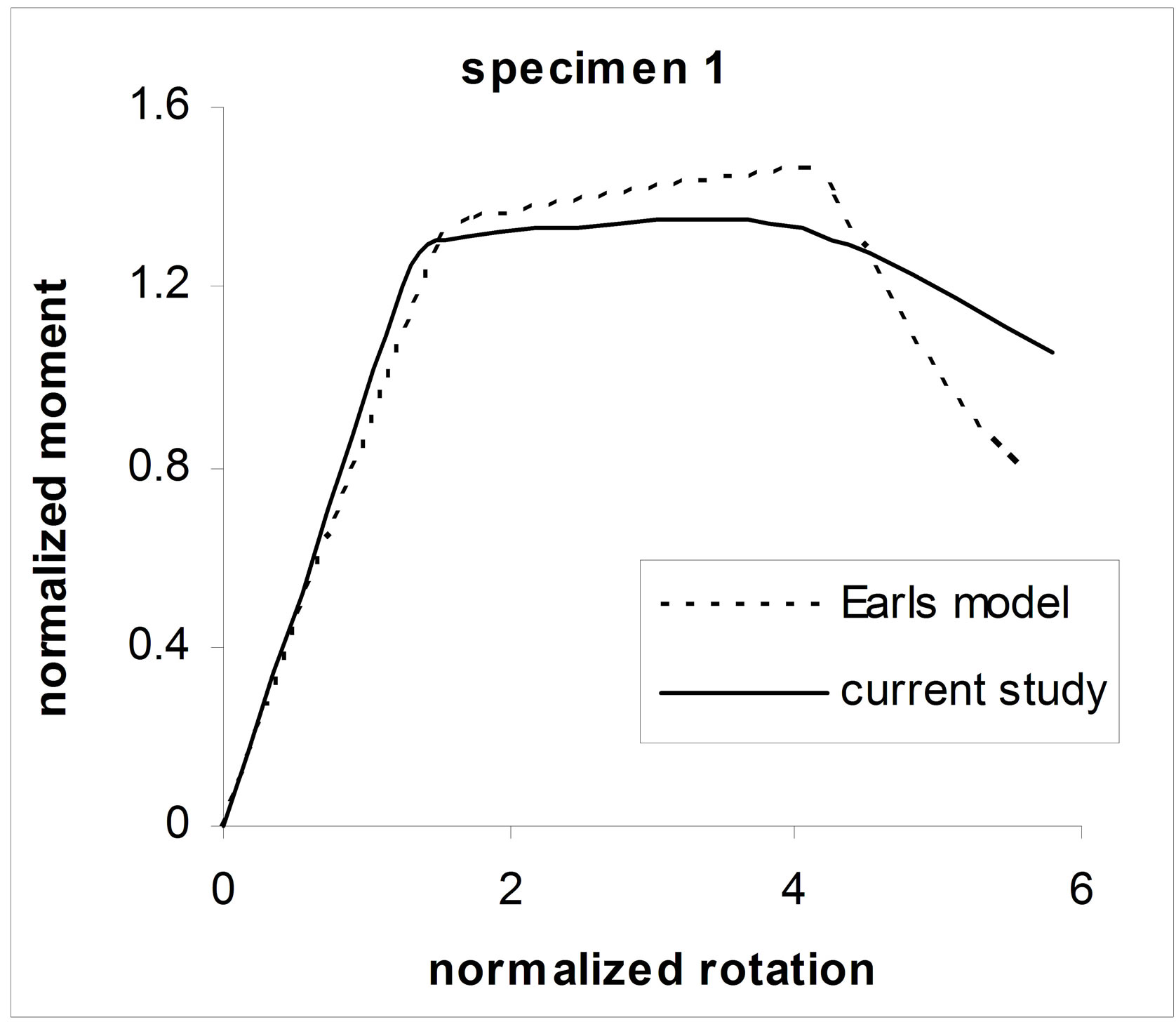
The results of numerical study of C.J. Earls [7] are used to evaluate the accuracy of modeling technique. Selected numerical study is done, to evaluate the inelastic failure of high strength I-shaped beams. The two specimens are used to verification of numerical modeling. The beams were 10WF25 hot-rolled sections made from A441 steel. These data resulted in a modeling idealization in which the yield stress was 354.4 MPa, and the ratios fu/fy = 1.49, eu/ey = 72.4 and est/ey = 9.66 according to Figure 8. It should be noted that Lb/ry is 45 and 37.5 for specimen 1 and 2 respectively. Lb is braced length.
Since the results of the investigation carried out by C. J. Earls is used herein for the verification of FE models, two parameters, namely normalized moment and nor-
 (a)
(a) (b)
(b)
Figure 6. Comparing FEM results and test results.

Figure 7. Final state of specimen “B”.
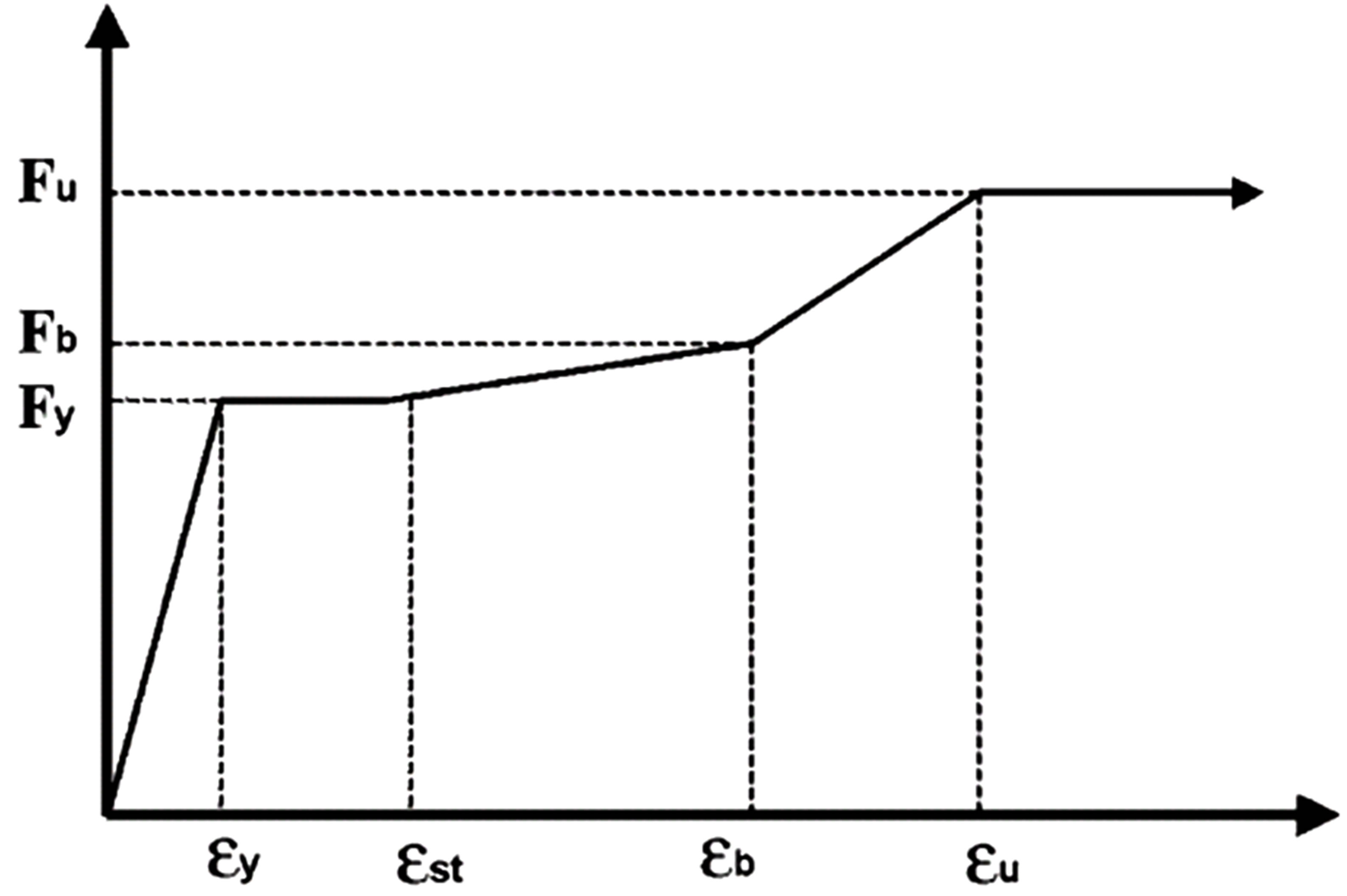
Figure 8. Uniaxial engineering stress-strain representation of the constitutive laws of the high-performance steels.
malized rotation, are used for presenting the beam moment-rotation behavior. Based on the definition of C. J. Earls, normalized moment is equal to M/My, where M is the moment applied on the member section at each instant and My is the moment causing the extreme crosssectional fiber to yield.
The normalized rotation is equal to θ/θy, where θ is the member section rotation at each instant and θy is the cross-sectional rotation resulting in the yield of the extreme fiber.
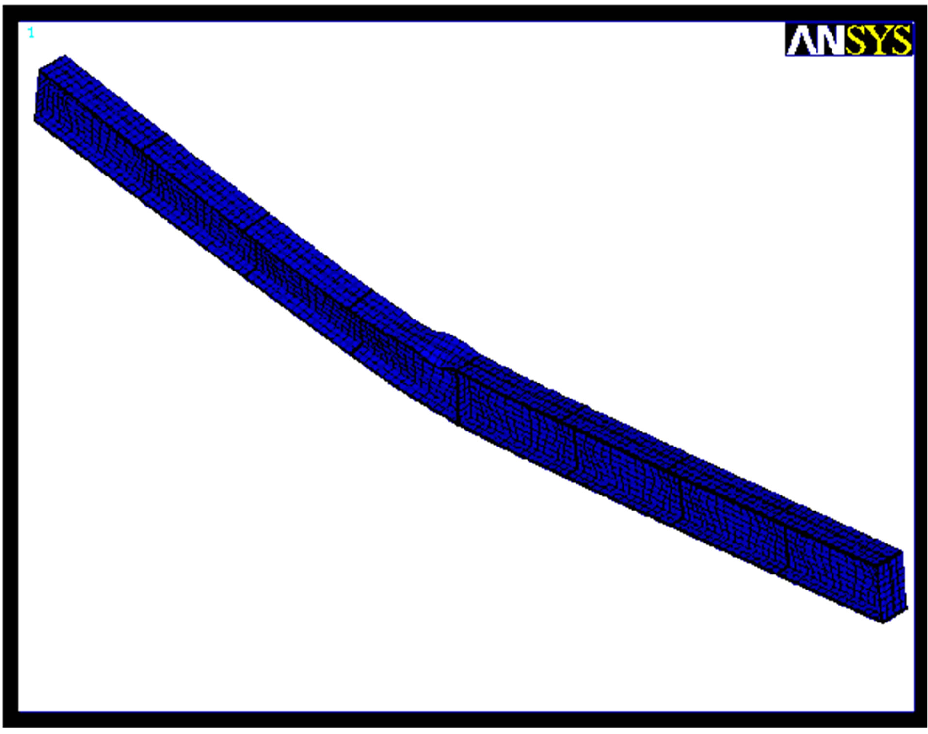
Figure 9 shows results of current modeling strategy in comparison with reference study. In linear range the both models have good agreement but in nonlinear range there a few different between two methods which rises from inherent difference between two finite element meshing and used elements, SOLID element and SHELL element that have different assumptions and basic theories. From Figure 10, the deformed shape of two models is conforming.
2.4. Results of Parametric Study
There are three models for each beam length: model of case1, model of case2 and plain-webbed model which the web of beam has no perforation.
 (a)
(a) (b)
(b)
Figure 9. Compression of two finite element models.
Rotation capacity of specimens calculated using Equation (1), given by AISC [1], where  is rotation when the moment capacity drops below Mp on the unloading branch of the
  plot, and
  is the rotation at which the full plastic capacity is first achieved.
 (1)
(1)
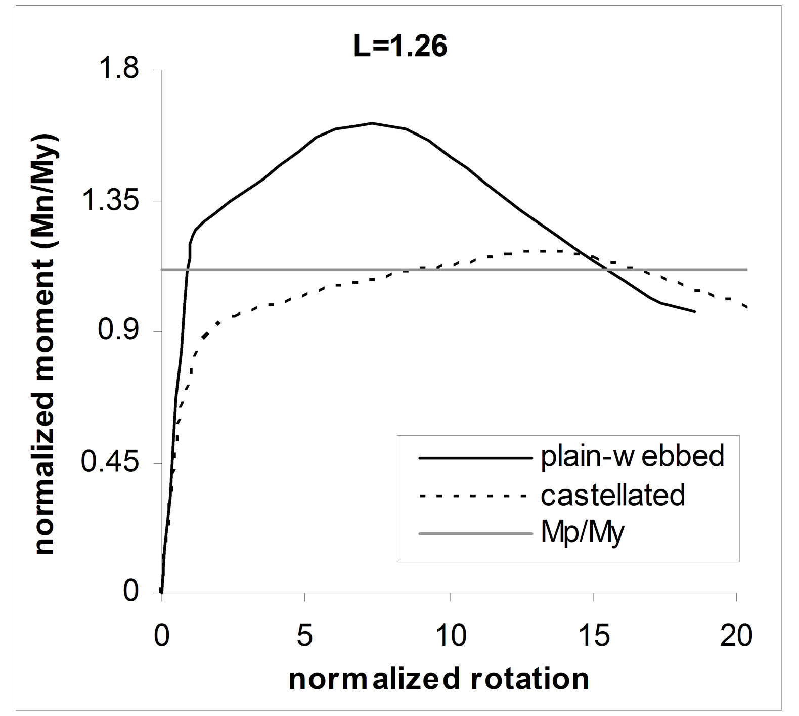
Case1: Moment-rotation curves of this type of bracing of beams are presented in Figure 11. In these plots the Mp/My refers to plain-webbed beams. The plots shows that for shorter beam lengths, the behavior of castellated beam is highly nonlinear before it reach to Mp/My. Increasing beam length yields more stiff behavior of beam in initial stages of loading and makes it closer to plainwebbed case. It may be because of the losing the effect of Vierendeel of the perforated regions. Increasing beam length heightens the flexural behavior of the specimens and as a result decreases the effect of Vierendeel mechanism. Buckling and failure modes of case1 specimens are combination of local buckling of top flange and out of
 (a)
(a)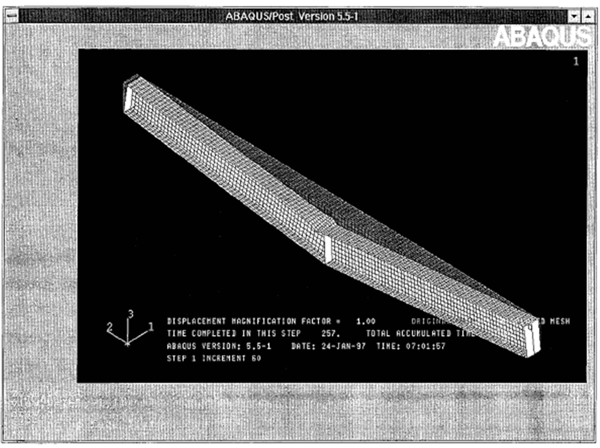 (b)
(b)
Figure 10. Compression of failure modes of current study whit Earls’ mode.
plane buckling of top flange.
Case2: This type of bracing is applied just for castellated beams and effect of web posts buckling on behavior of castellated beam is studied. Restraining top flange of beam against out of plane motion prevents it’s out of plane local buckling so in this condition there is just web buckling mode of failure. Moment-rotation plots of case2 models presented in “Figure 12”.
This bracing pattern yields more rotation capacity of specimens. Similar to case1 initial branch of curves are more nonlinear for shorter beam lengths.
General information of specimens is listed in Table 1. The Lp in the table dominates the bracing length needed to plastic buckling of the beam, My and Mp are yield moment and plastic moment capacity of the plain-webbed beam respectively. Rp and Rc are the Rotation capacity of plain-webbed and castellated beams restrained as case1 respectively. The term Mp/Mc ratio in last column of Table 1 is the respect of the maximum moment capacity of
 (a)
(a) (b)
(b)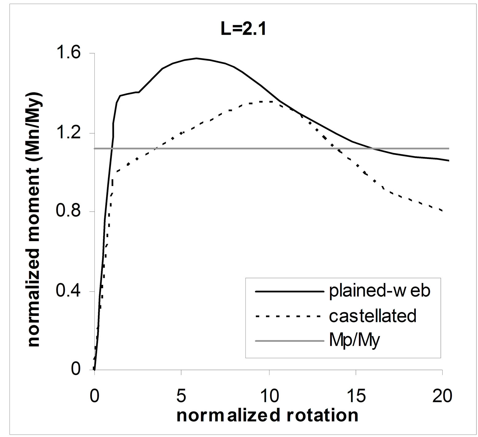 (c)
(c) (d)
(d) (e)
(e)
Figure 11. Moment-rotation curves of case1 type of bracing.
the plain webbed beam to case1 castellated beam.
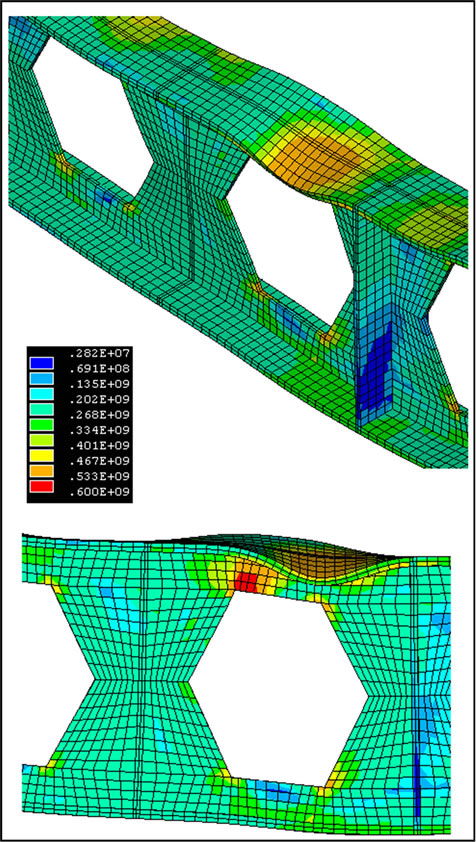
From Table 1, it is cleared that web perforations affects the rotational capacity of the beams more than moment capacity especially for shorter bracing length. Figure 13 shows Von Misses stress distribution and deformed shape of S10 specimen. Figure 13(a) shows the state of the specimen at its maximum strength. Local buckling of compression flange at mid span near adjacent the stiffener, causes stress concentration in top-right corner of web post. Increasing the load, increases the stress intensity in
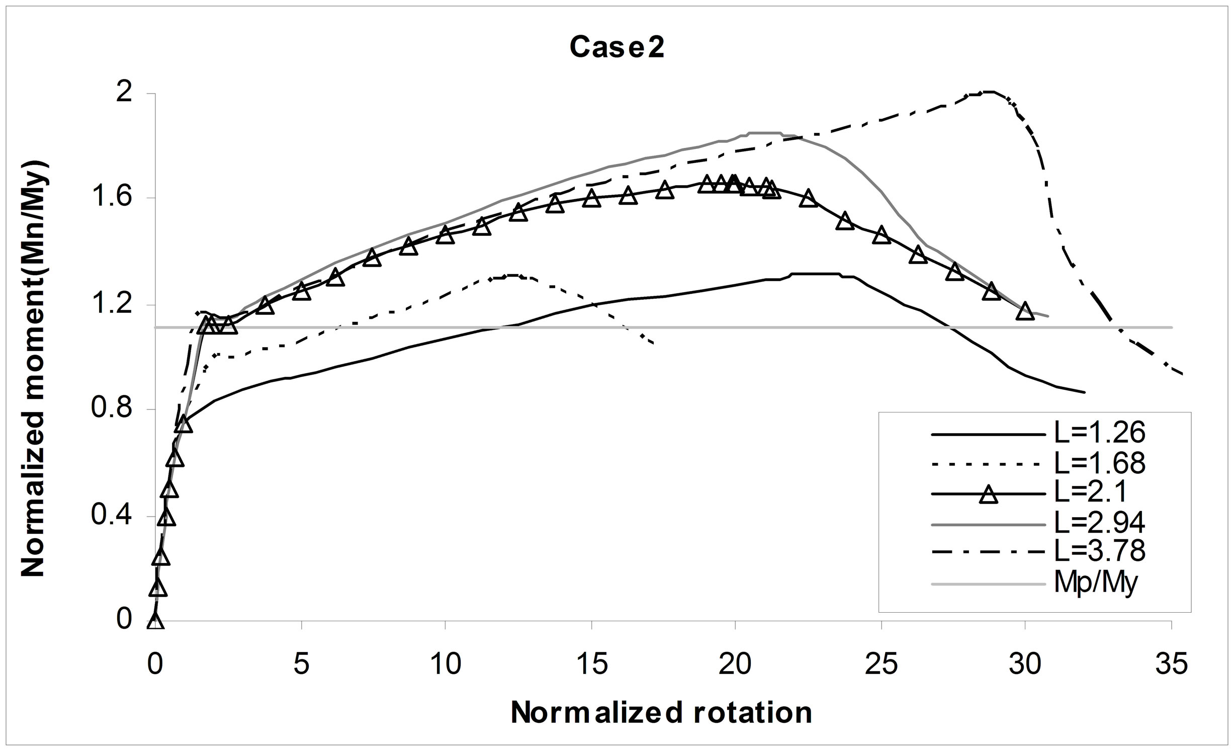
Figure 12. Moment-rotation plots of case2 models.
 (a)
(a) (b)
(b)
Figure 13. Von Misses stress distribution and deformed shape of model S10-C1 mid span. (a) At the maximum strength; (b) At the ultimate strength.
buckled region, web post corner and beam deformations till the occurrence of the combined three failure modes: local buckling of top flange, web post buckling and out of plane buckling of web post, at the final state Figure 13(b).
3. Conclusion
Moment-rotation behavior of castellated steel beams were compared with corresponding plain-webbed beams in this research. The numerical modeling of plain-webbed beams has verified comparing numeral model of other researchers. The comparisons has shown a better agreement in linear range than nonlinear range of beam behavior during, material constitutive models, residual stresses and applied basic theories. Simply supported castellated beams have modeled subjected to concentrated central load at mid-span to study the rotational capacity of this type of beams. Two types of restraining of castellated beams were studied: Case1: restrained out of web plain all nodes at supports and bottom flange nodes. This bracing was applied to plain-webbed specimens also. Case2: restrained top flange nodes in addition to case1 restraining. In this case being out of plain buckling of web posts was possible. The results of case1, for both of the castellated and the plain-webbed models were used in comparison and it was cleared that web perforations, reduces the beam ductility till 54.7% and also the ratio of maximum flexural capacity of plain-webbed beams to the castellated beams is 1.39. For case2, the results of analyzing models showed that increasing beam length increases the rotational capacity due to increasing (M/V) ratio which dominates the reduction of shear force.
4. Acknowledgements
The authors would like to thank the Dr. Saedi Daryan for his kind help.
REFERENCES
- American Institute of Steel Construction (AISC), “Load and Resistance Factor Design Specification for Structural Steel Building,” AISC, Chicago, 1999.
- R. Redwood and S. Demirdjian, “Castellated Beam Web Buckling in Shear,” Journal of Structural Engineering, Vol. 124, No. 10, 1998, pp. 1202-1207. doi:10.1061/(ASCE)0733-9445(1998)124:10(1202)
- W. Zaarour and R. Redwood, “Web Buckling in Thin Castellated Beams,” Journal of Structural Engineering, Vol. 122, No. 8, 1996, pp. 860-866. doi:10.1061/(ASCE)0733-9445(1996)122:8(860)
- A. Mohebkhah, “The Moment-Gradient Factor in LateralTorsional Buckling on Inelastic Castellated Beams,” Journal of Constructional Steel Research, Vol. 60, No. 10, 2004, pp. 1481-1494. doi:10.1016/j.jcsr.2004.02.002
- C. J. Earls, “On the Inelastic Failure of High Strength Steel I-Shaped Beams,” Journal of Constructional Steel Research, Vol. 49, No. 1, 1999, pp. 1-24. doi:10.1016/S0143-974X(98)00204-1
- C. J. Earls, “Geometric Factors Influencing Structural Ductility in Compact I-Shaped Beams,” Journal of Structural Engineering, Vol. 126, No. 8, 2000, pp. 860-866.
- C. J. Earls, “Constant Moment Behavior of High-Performance Steel I-Shaped Beams,” Journal of Constructional Steel Research, Vol. 57, No. 7, 2001, pp. 711-728. doi:10.1016/S0143-974X(01)00012-8
- S. Daryan, “Parametric Study on the Moment-Rotation Behavior of Castellated Beams,” MS Thesis, K. N. Toosi University of Technology, Tehran, 2005.
- ANSYS User’s Manual, “Version 5.4. 201 Johnson Road,” ANSYS Inc., Houston, 1989.
- T. Belytschko, W. K. Liu and B. Moran, “Nonlinear Finite Elements for Continua and Structures,” John Wily & Sons, New York, 2001, pp. 317-43.