Open Journal of Safety Science and Technology
Vol.2 No.3(2012), Article ID:22585,4 pages DOI:10.4236/ojsst.2012.23009
Aspects of Transformer Fires in Brazil
Departamento de Engenharia de Mecânica, Universidade Federal de Pernambuco, Recife, Brazil
Email: duarte@ufpe.br
Received April 13, 2012; revised May 16, 2012; accepted May 28, 2012
Keywords: Transformer; Fire; Performance; Globalized Economy
ABSTRACT
For the last 20 years blackouts have been included in the list of major disasters that includes storms, hurricanes, earthquakes and floods. Therefore consumers have become increasingly aware of fires and explosions involving oil-filled transformers located in power plants or substations. Owing to several fires in transformers, the summer of 1997 became known to the people of Rio de Janeiro, Brazil, as the The Summer of Blackouts. The losses incurred by a blackout are not merely financial. In fact, the loss of operational utility by fire represents only a minor part of the total overall cost in terms of energy availability, human loss and organizational reputation. The costs resulting from the lack of fire risk management in the electrical power industry are no longer acceptable to Brazilian society. The objective of this paper is to address important aspects of transformer fire risk in the context of the Brazil. The aim is to help engineers recognize the implications of decisions concerning the operation of transformers over their life cycles.
1. Introduction
Transformers are crucial not only to power system performance and reliability of supply, but also to persons (i.e. employees and third parties) and property located in their immediate vicinity, in the event of a failure resulting in a fire or explosion. A transformer failure can sometimes have serious consequences on the environment due to the discharge of dielectric fluid. These consequences are a function of location (i.e. proximity to waterways, whether indoors, etc.) and the presence of passive measures, such as rock-filled pits. The direct impact of a transformer failure can jeopardize the image of the electricity company. The technical complexities, high capital cost and long life expectancy pose unique decision-making challenges to engineers and managers who are responsible for the safe operation and maintenance of transformers on a day-to-day basis.
As globalization has had a significant impact on transformer manufacture over the last 25 years, this paper has been designed to help engineers understand the failure mechanism of transformers and the consequences thereof.
2. The Brazilian Experience of Transformer Fires
Brazil has an installed capacity of about 94,000 MW. Most of this energy comes from hydroelectric power plants, accounting for around 81,000 MW. Demand in Brazil is approximately 60,000 MW and there are approximately 75,000 km of transmission lines. Transformer capacity is currently about 171 GVA, and in the next eight years it will increase by 50%.
In the fire design of our substations, the usual focus is compliance with national and international codes and standards. Although during construction the plans and specifications are duly followed, what is rarely done is a considered harmonization of fire defenses by trained and skilled fire safety professionals in order to provide identifiable performance criteria: damage indicators and goals based on those involved in the project design, construction, operation and maintenance, considering both the organizational viewpoint as well as outside needs and desires. Meanwhile, differences in opinion concerning code interpretation and the understanding of fire and fire defense behavior by engineering design teams lead to very different performances among substations. The vast inventory of existing substations that have been constructed under different codes and conditions enables us to recognize the fire risk variability that exists in the electrical power industry. Even though the design theme and organization may produce a substation compliant with codes, standards and good practice, these credentials do not assure safety from fire. The prevailing assumption among many employees, regulators and the organizational culture has been that fire safety can be achieved through a combination of common sense and enforcement of prescriptive codes and standards. These methods should suffice in a simple workplace producing simple and unchanging products. However, today’s power plants and substations are highly complex and constantly changing, requiring a more effective approach to fire safety.
It is not difficult to identify substations or hydroelectric power plants in which, despite both active and passive fire protection barriers, a fire has caused extensive destruction. In Figure 1, an autotransformer of 150 MVA protected by a spray system caught fire as a result of a bushing failure. The spray system did not operate when the fire began. Due to the oil leakage through the base of the bushing, this delay caused the fire to spread. NFPA 15 describes water spray design for transformers. Even if suppression systems are available, there are many uncertainties concerning their success or failure in controlling the fire. The questions that arise include: Can water be discharged from the spray system? Can water extinguish the fire? Water will be discharged from the spray system if all water supply valves are open, but when the sensor fuses, will enough water reach the spray head? Moreover, the violent nature of a transformer fire could render an automatic spray system useless. Although this has happened on a number of occasions, the automatic spray system survived the explosion and was credited with controlling the fire, limiting damage and minimizing system downtime. As the system in which the transformer is inserted has a dynamic behavior, the various fire scenarios are subject to many uncertainties.
Traditional fire defenses provide a tool kit for protecting the substation. Their installation and maintenance have an important influence on substation performance in the event of a fire (see Section 4). Evaluations should involve an understanding of individual component (micro) behavior and an interactive (macro) behavior of the complete electrical system.
Figure 2 shows the result of a transformer fire which rendered the substation unavailable and left about one million people without energy, because the structures that supported the overhead bus collapsed.
Figure 3, a fire in a generator step-up transformer spread to other units due to poor design of the fire wall
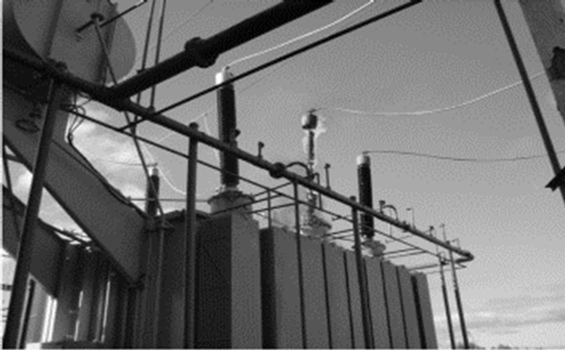
Figure 1. Escalation of a transformer fire.
and the rock-filled pits. Rock-filled pits are a passive control measure against soil contamination in the event of a major transformer oil leak and fire. As well as a flowing liquid fire, it is also important to prevent a Boiling Liquid Expanding Vapor Explosion (BLEVE). A rock-filled pit should use clean rocks of a certain size and extend to a defined depth in order to ensure that the flow of burning oil through the rock layer is sufficiently fast to cool the oil and extinguish the pool fire.
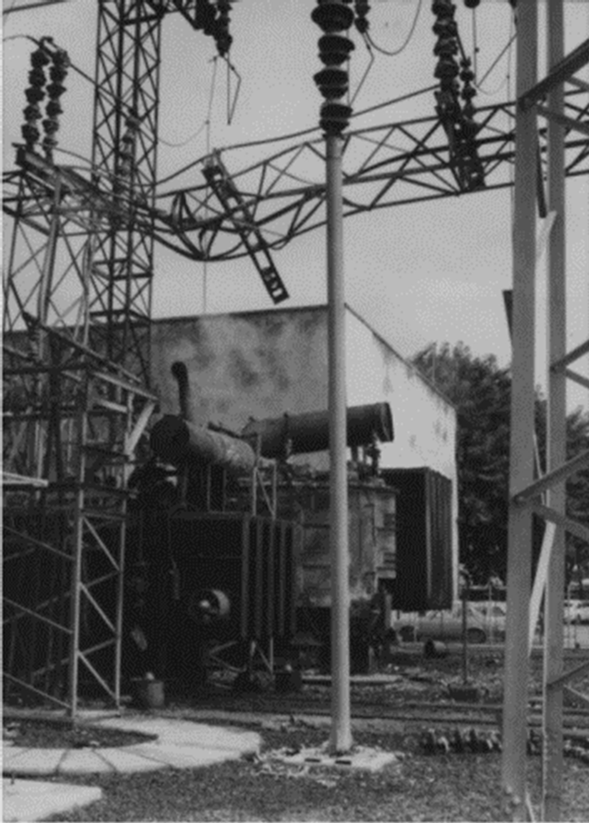
Figure 2. Collapse of overhead bus due to a fire.
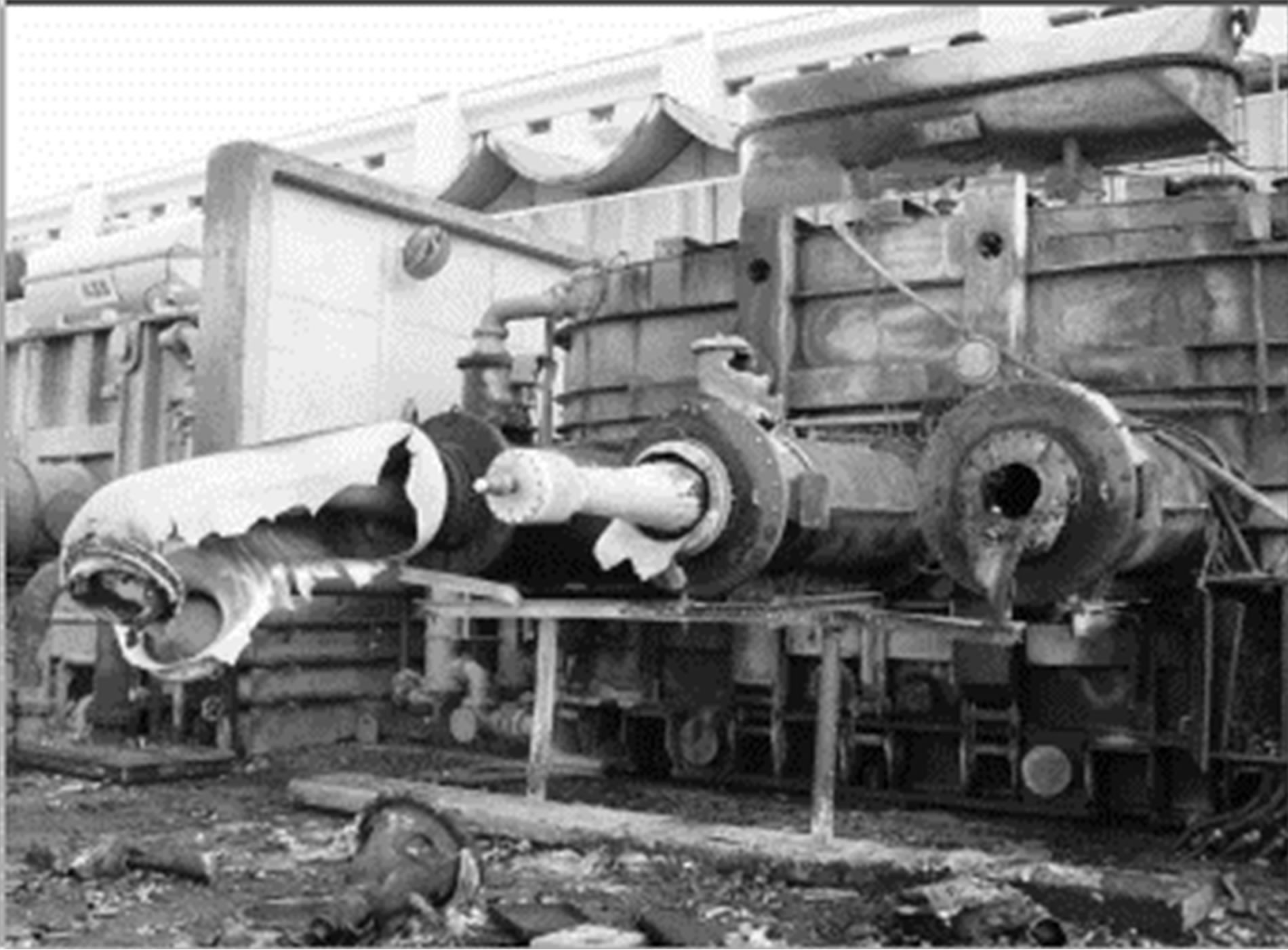
Figure 3. A transformer fire caused by bushing failure.
A transformer in a 500 kV substation was operating under normal conditions when the spray system was activated by a false alarm. As the sprinkler head was placed facing the bushing instead of the transformer tanker, an external arc was created which caused the rupture of the bushing and led to a fire. NFPA 15 states that nozzles must be positioned in such a way that the water spray envelope does not directly impinge on the energized bushing. The Brazilian experience shows without doubt that installation control is crucial.
Three transformers caught fire in a substation. Only one of the transformers was protected by a spray system, whilst the other two were not. The protected transformer’s spray system controlled the fire and the impact was minimized, i.e. the transformer was repaired. One of the unprotected transformers caught fire on a day of heavy rain and the other on a hot summer day (the ambient temperature was around 30˚C). The heavy rain protected the first unprotected transformer and it could be repaired. But the other unprotected transformer, which caught fire in summer, did not survive.
The location of a transformer in the context of a power plant may affect its mission and business objectives if a fire occurs. Some organizations ignore the fire risk in the hope that such an unfortunate event will not happen. Others assume that if a fire does occur, the decision on what to do will be taken at the time. Figure 4 shows the transformer location in the context of a power plant: if a transformer fire occurred in this case, the combustible products could flow into the turbine inlet system.
Transformer fires have resulted in unacceptable consequences for companies and society as a whole, such as:
1) A bushing failure resulted in fragments of bushing ceramic being propelled beyond the perimeter of the substation, thereby putting people and buildings at risk.
2) A transformer explosion created a blast pressure that impacted adjacent properties and structures. The blast waves also destroyed the fire protection measures around the transformer (such as the water spray system).
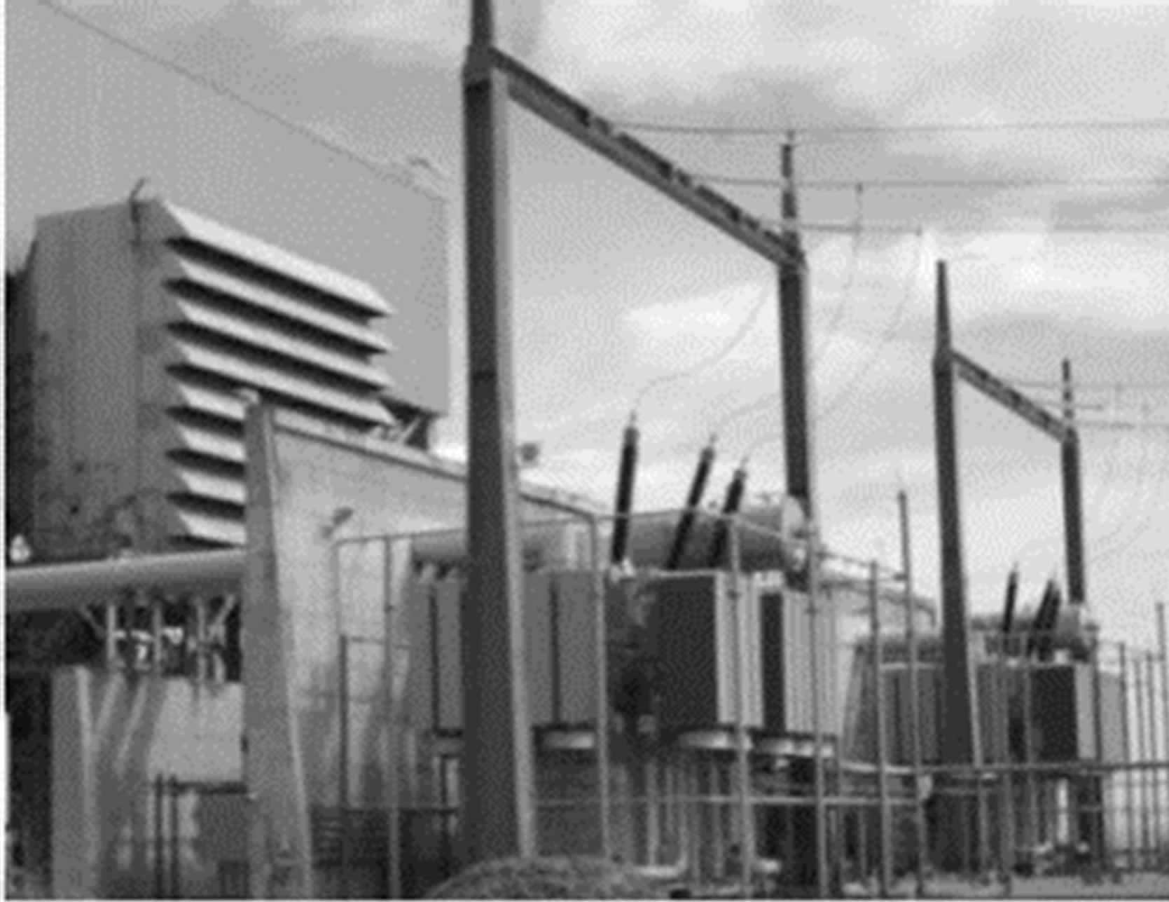
Figure 4. Detail of a power plant layout.
3) An insulating oil-pool fire caused ignition of combustible structures inside and outside the installation perimeter.
4) A transformer oil-spill fire spread because suitable oil containment was not installed. The resulting spill fire impacted other equipment and structures both within the substation and outside the perimeter.
5) Examples of transformer oil-pool fires impacting structures and equipment:
5.1) The heat flux from a transformer fire ignited exposed combustible surfaces. It also caused the failure of ceramic bushings on adjacent equipment as fireproof walls were not installed.
5.2) Radiation from the fire exposed the steel overhead bus structure to temperatures well above the yield temperature, causing failure.
5.3) An insulating oil pool fire created a very large fire plume. Due to high wind speeds, the fire plume tilted significantly and exposed adjacent equipment, buildings and other structures, as well as causing significant soot deposits in the downwind plume area (Figure 5).
Properly designed installation and maintenance of both passive protection and active barriers can mitigate the impacts of a transformer fire. The next paragraph provides an overview of philosophies applied to dealing with fires in Brazil. Depending on the company’s safety culture, it may adopt one, two or all of these approaches.
Fire prevention philosophy requires the selection of materials and design features that will prevent or lower the risk of transformer fire. Using natural ester as a dielectric, for example.

Figure 5. Fire plume from a reactor fire.
Fire protection philosophies are measures that are incorporated into the transformer environment to mitigate or reduce fire hazards. These measures should include:
1) Life Safety. The occupant should be able to leave the location where the transformer is installed without being subject to hazardous or unbearable conditions, such as thermal exposure, carbon monoxide, carbon dioxide, smoke and other gases. Firefighters should also be able to rescue occupants and prevent the fire spreading.
2) Passive Measures. Static measures that are designed to control the spread of fire and withstand the effects of fire, such as firewalls and rock-filled pits.
3) Active Measures. Automatic fire protection measures that warn the occupants of the existence of fire, and extinguish or control the fire. These measures are designed to automatically extinguish or control a fire at its earliest stage, without risking or sacrificing property. The benefits of these systems have been accepted by authorities and insurance companies.
4) Manual Measures. Include items such as the various types of fire extinguishers, fire hydrants, hose station, etc. requiring active participation by company staff or the fire department.
If fire prevention and fire protection measures are not incorporated, it is expected that the local fire department or company fire brigade will have to fight the fire manually. The transformer fire will be extinguished and the fire department will have contributed to this outcome. The success of this event is not that the fire will eventually be put out, but whether the fire department will extinguish the transformer oil-pool fire before it spreads. What is the probability that the fire department will prevent the fire spreading to other areas or involve other equipment? The fire suppression philosophy can have a significant impact if a fire occurs. A fire may have a very low cost initially, but may result in significant losses of assets, revenue and customer services.
Fire recovery should provide measures to recover the transformer and its surroundings in the event of a catastrophic fire. There are companies that have an inventory of transformers. It is highly recommended for specific and critical scenarios to guarantee the operational continuity of the system.
3. Transformer Fire and Installation Layout
Many transformers have been fitted with water-spray systems to combat the effects of fire, but these systems only serve to limit collateral damage in the substation and cannot prevent initial fire. The fire safety aspects of the installation are also neglected at the design stage. Fire risk analysis of the layout of several substations has unequivocally shown that, when there is some fire protection, its effectiveness is questionable, because it was introduced in isolation from the rest of the system (as will be shown in the following paragraphs). Figure 6 shows details of the layout of a 230/69 kV substation. This substation was initially designed, constructed and operated for some years without firewalls. Firewalls were constructed at a later stage, probably because a transformer fire in another substation without firewalls destroyed the transformer adjacent to the one on fire. As firewalls exist to protect adjacent transformers in the event of one catching fire or exploding, firewall failure may result in the loss of additional transformers. Although the firewalls were designed to resist fire for 4 hours, studies conducted by Duarte et al. [1] showed that they can start to collapse after just one hour. In Figure 7, the grey area shows that the structural integrity of the firewall was compromised, since compressive and tensile stress exceeded the values of 150 kg/cm2 and 15 kg/cm2 respectively.
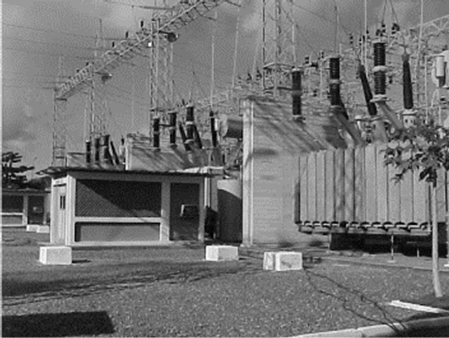
Figure 6. Detail of substation layout.
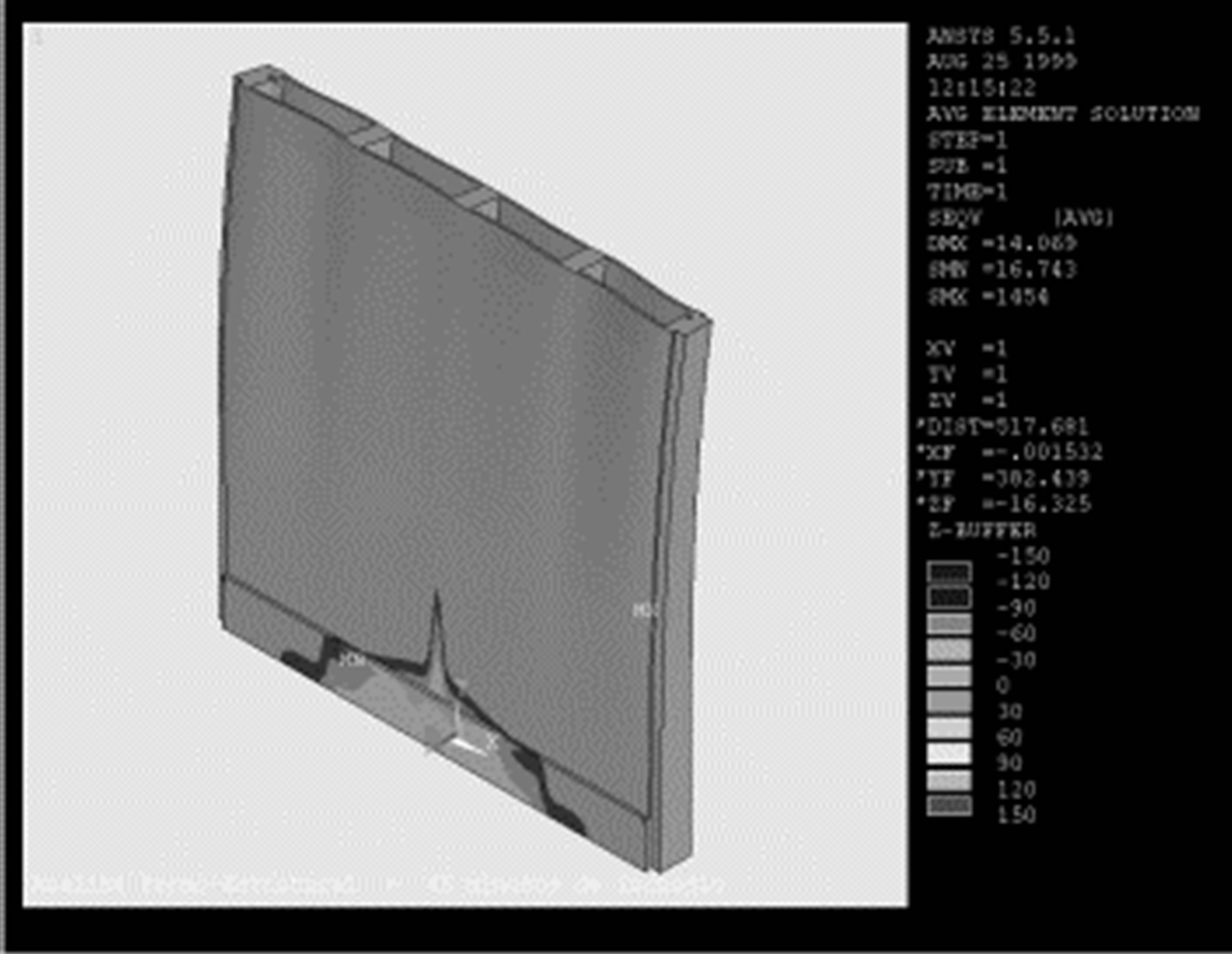
Figure 7. Von Mises tension test on firewall after 60 minutes.
Why did the engineers who designed the firewall believe it had a fire resistance of more than 4 hours? They did not take into account the energy released by a fire or explosion. They did not ask the following question: what will the energy release be if a fire or explosion occurs in one of the transformers? The answer involves the quantification of the physical phenomena involved in a fire or explosion. What is surprising is that the design team thought that all the transmission transformers were protected against a possible fire. About a hundred firewalls of the same design were constructed in other substations of the transmission network managed by this company. However, since the transmission transformer specifications are not the same for the entire network, the energy released during a fire or explosion differs among transformers in operation. The energy release depends on such things as the transformer capacity, distance between the transformer and the firewall, type of fire resulting from the transformer failure, oil characteristics, wind velocity and direction. As a result, some of the firewalls of this particular transmission network are over-dimensioned and others under-dimensioned.
For the substation shown in Figure 6, it is also important to note the relay houses. Some of the protection, bypass and control circuits that control the transformers and other substation equipment are installed in the relay house. In this particular substation there are two relay houses whose structure is masonry with glass windows. A structural thermal performance simulation of one of the relay houses during a transformer pool-fire was carried out using the finite elements method. The distance between the transformer and the relay house was 3.50 meters. Ninety minutes after the fire started, the wall temperature distribution showed some wall temperatures to be above 300˚C. Although such high temperatures can cause wall failure, the structural integrity of the walls, pillars and beams was maintained for 117 minutes after the fire started. 45 minutes after the fire started, the glass windows would break, so there would be a rapid increase in the gas temperature inside the relay house. The heat impact would cause irreversible damage to the electronic panels. Analysis of gas temperature distribution inside the house showed that temperatures higher than 70˚C would be reached in approximately 30 minutes.
Eventually a substation fire will be put out and either the company fire brigade or local fire department will have contributed to this outcome. The success of this event is not whether the fire is extinguished; the question is not the overall probability of the fire being controlled, but rather the probability of the fire being controlled when it is 1 kW, 5 kW, 10 kW, 50 kW...n kW. The success of the event is to control the fire before it causes further impact on the operational continuity of the substation. An inappropriate layout in the event of a fire (Figures 4 and 6) can spread the impact to other parts of the substation. The time necessary to re-integrate the substation into the network will thus increase, even without considering the other costs involved. The compatibility of the substation layout with fire behavior is important to understanding the substation’s post-fire operational continuity.
4. Fire Protection Evaluation
Electricity is taken for granted and it is only when the lights go out and our daily routines seem to go into slow motion that we suddenly become aware of our dependence on power plants, transmission lines and substations. Consumers have become more aware of an increase in fires and explosions involving oil-filled equipment. The recognition of the fire hazard, the risks involved and appropriate fire protection and mitigation measures are some of the key considerations for the design and operation of new or existing hydroelectric power plants and substations.
There is a wide range of types and causes of fires that can occur in power plants or substations. The types of fires depend on the equipment, the systems used in the station and the layout. Energized electrical cables with a combustible insulation and jacketing can be a major hazard because they are a combination of fuel supply and ignition source. A cable failure can result in sufficient heat to ignite the cable insulation, which may continue to burn and produce great heat and large quantities of toxic smoke.
Some of the specific components encountered in a substation that are fire hazards are oil-insulated transformers and circuit-breakers, hydrogen cooled synchronous condensers and standby diesel generator buildings. A control or relay house can contain potential hazards such as batteries and charging systems, combustible waste, exposed combustible constructions, switchyard cable openings that have not been fire-stopped, offices, emergency generators and other noncritical facilities.
Fires in indoor substations are also caused by some of the same substation-related hazards found in switchyards and control rooms. The basic problem with a major fire in indoor substations is that the building will contain the blast pressure, heat and smoke, which can result in blast and thermal damage to the building’s structure as well as smoke damage to other equipment i.e. corrosion damage.
The hazard created by mineral oil-insulated equipment such as transformers, reactors or circuit breakers is that the oil is a significant fuel supply that can be ignited by an electrical failure within the equipment. Infiltration of water, failure of core insulation, exterior leakage currents and tap-changer failure are some of the causes of arcing within the mineral insulating oil that can result in a fire. This arcing can produce breakdown gases such as acetylene and hydrogen. Depending on the type of failure and its severity, the gases can build up sufficient pressure to cause tanks or bushings to fail or rupture. Once the tank or bushing fails there is a probability that a fire or explosion will occur. A possible explosion could cause blast damage. The resulting oil spill fire could spread to form a large pool of fire, depending on the volume of oil, spill containment, slope of the surrounding area, and the type of surrounding ground cover. Thermal radiation and convective heating from the oil spill fire can also damage surrounding structures and structures above the fire area.
Oil-insulated equipment is the main source of substation fire [1]. Transformer oils are typical Class III B liquids. According to FM Global Data Sheet 5 - 4 and NFPA 325, the flash point of transformer oil is 146˚C - 300˚C. The form of fire protection for oil-insulated transformers depends on the size and importance of the transformer. For example, a single transformer under 10,000 kVA can probably be protected by portable extinguishers. A single transformer over 10,000 kVA should have hydrant protection. Single transformers over 100,000 kVA should have a fixed automatic water spray system. Multiple transformers over 10,000 kVA should also be separated by 8 m of open space and/or noncombustible barriers between the units or be protected by a fixed water spray system.
Transformers are typically oil-cooled, and the application of a water spray to a transformer oil spill or fire can control or extinguish the fire by emulsification of the oil (Figure 8). When water and oil (immiscible liquids) are agitated together and one of the liquids is dispersed throughout the other, this causes a cooling effect on the oil surface, preventing the release of flammable vapor.
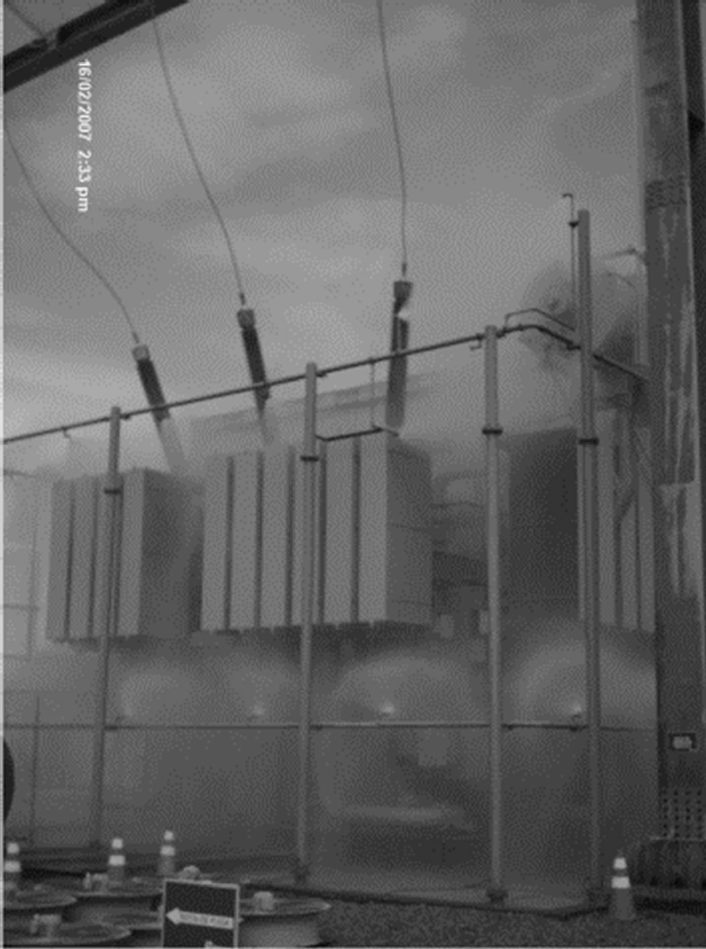
Figure 8. Water spray system.
On the other hand, if water is unavailable, a dry chemical system should be considered as a suitable alternative, especially if the transformer is in an enclosure. Although dry chemical systems are effective for extinguishing oil fires, their limited capacity generally make them a second choice to water. If the transformer is located outdoors, the system should be designed to operate successfully against adverse winds. A fixed carbon dioxide system is usually of questionable value outdoors owing to wind effects. Although foam is effective on flammable liquid fires, it may act as conductor of electricity, and should therefore not be used on or near energized equipment.
Fire suppression of a non-sprinkler-protected transformer is completely dependent on passive barriers, such as separation space, fire-resistant walls and enclosures that confine the oil in the event of oil leakage or tank rupture. On the other hand, if an automatic fire suppression system is present, its reliability to act successfully depends on project design, installation and maintenance (Figure 9). The project design describes manufacturing quality control of all water-spray components (waterspray nozzles, pipes and tubes, joining of pipes and fittings, hangers, control valves, etc.). NFPA 15 describes water spray protection design for transformers. Installation is related to the quality control of the construction process, whilst the success of system operation also depends on long-term maintenance. If maintenance of the system is not a priority, the reliability will deteriorate and its operational level will worsen. After successful installation, only event actuation can change over time.
The concept of fire design is an essential part of every fire component evaluation, because it affects fire defense performance. The fire design identifies the rate of heat-
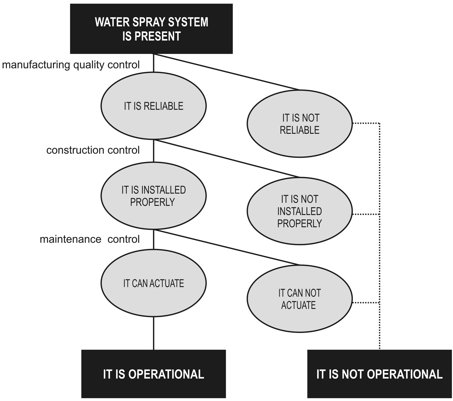
Figure 9. Reliability of the water-spray system.
release, the speed of fire growth for a series of scenarios, and the incident energy on a target. The fire design can be estimated using the fire and explosion models available in the literature. The vulnerability models provide an estimate of the effects of the physical phenomena on the receptors (i.e. people, structures/building and environment).
A water-spray system usually involves heat-actuated detectors operating an automatic mechanical flooding valve that supplies water to projectors (i.e. spray nozzles) arranged over and around the unit being protected. When the activated detectors call for water, a number of system components must function in order to deliver the water to the projectors. The application of the agent is an expression of the success or failure of water flowing through valves to the projectors. It is essential to have an adequate pressure and flow rate. The expected performance of the water spray system can be evaluated based on information about its reliability and operational effectiveness, as shown in Figures 10 and 11.

Figure 10. Evaluation of water-spray system.
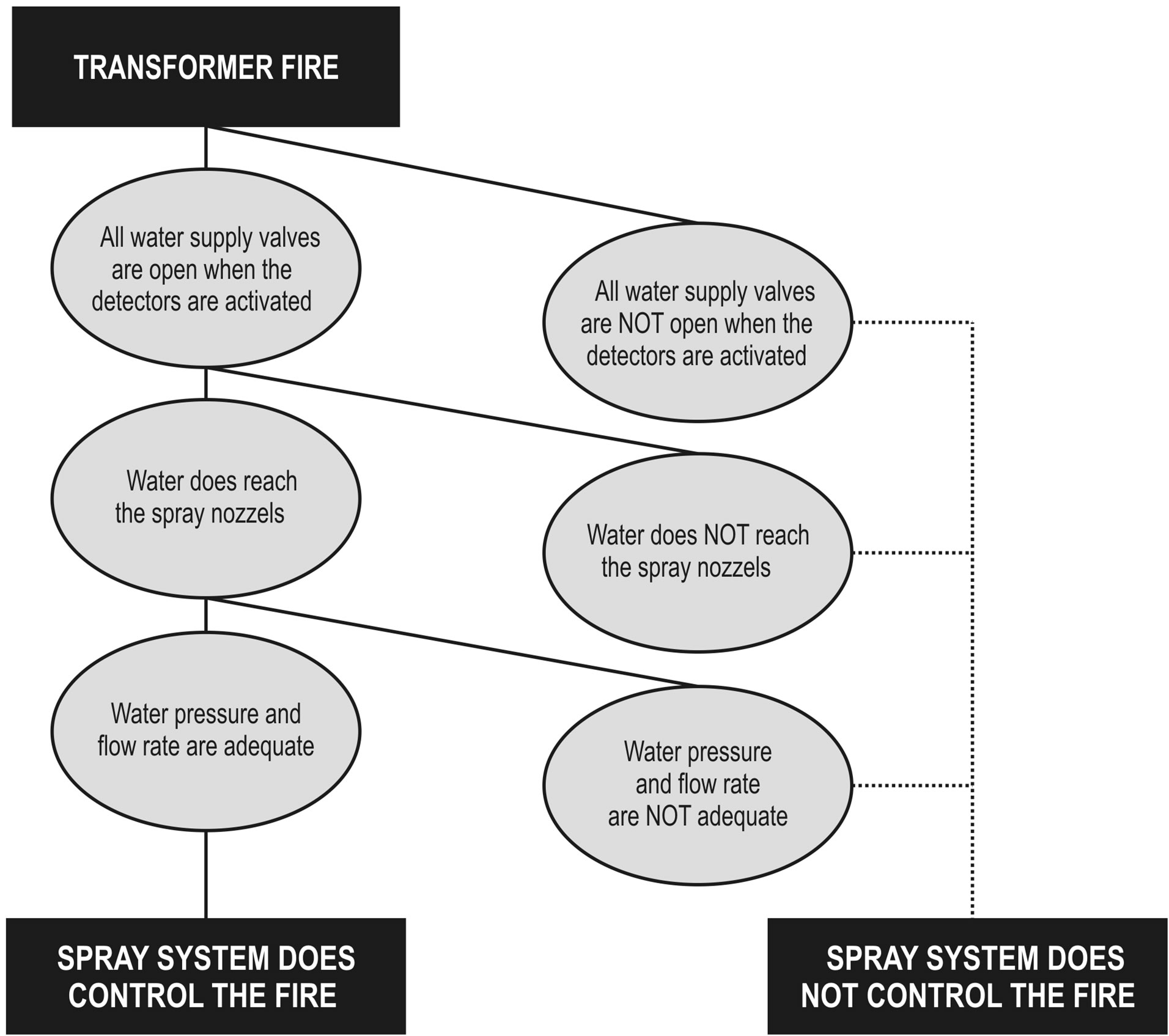
Figure 11. Success or failure of the agent application.
The efficient design of fire safety for an installation depends on obtaining answers to the following questions: What can go wrong? How will the installation safety barriers (i.e. preventive and protective measures) react to a fire or explosion? What will be the consequences if the barriers fail? The first question consists of a systematic identification of the initiating events as well as the combined sequences of events that can lead to a fire or explosion. In other words, what has not been identified cannot be assessed or mitigated. The following paragraphs present several fire scenarios.
5. Transformer Fire Scenarios
Transformers are generally highly reliable and failures are rare. Although most transformer faults do not lead to a fire or explosion, some combinations of latent faults may result in a catastrophic transformer fire. Cooper [2] and Medina [3] examined a number of case histories and concluded that the following circumstances could lead a transformer fire and explosion.
1) Failure of inter-turn insulation in the main windings, probably as a result of overheating due to obstruction in oil circulation; mechanical damage during manufacture; moisture penetration between turns; overheating due to overvoltage or overload; and relative movement between turns.
2) Insulation failure between winding and transformer tanker caused by aging or deterioration of insulation, or moisture entry into oil.
3) Failure of magnetic circuit, leading to excessive eddy currents in the core.
4) External causes, such as rapidly fluctuating load, steep-fronted surge voltage and external short circuit on the secondary side.
5) Miscellaneous faults: failure at connections or bushing; inadequate design or a design unsuited to the service for which the transformer was installed; inadequate spring tension on tap-charger contact springs; ignition of vapor above the oil level; and inadequate maintenance.
According to Ronningen [4], if an arcing fault occurs within the transformer, ejection of oil aerosol can occur, possibly accompanied by a physical explosion of the transformer tanker (Figure 12). If the oil is ignitable, a serious fire or a vapor/mist explosion can happen. When an arc occurs in ignitable oil, hydrogen and acetylene are the main gases produced. By contrast, breakdown of oil due to excessive conductor temperature yields mostly ethane, ethylene and methane, with smaller amounts of hydrogen. Benton [5] suggests the following sequence of events leading up to a transformer explosion:
• A heavy overload degrades the oil sufficiently to cause a fairly high leakage current.
• The leakage current further degrades the insulation

Figure 12. Sequence of event that can lead to transformer explosion (adapted from Ronningen [4]).
(i.e. oil, paper or wood) and eventually leads to a turn-to-turn or layer-to-layer fault.
• The fault becomes large enough to cause the primary fused cutout to operate.
• Upon re-fusing and re-closing the cutout, the transformer insulation fully breaks down, drawing a very large arc fault current.
• The energy released from the arc gasifies the transformer oil, primarily into hydrogen and methane.
• Rapid pressure building from the gasification causes the transformer cover to be blown off.
• The combustible escaping gases ignite either due to remaining arc energy or due to sparking associated with rapid metal breakage.
As pressure relief devices are generally effective only for slowly rising overpressure events, they do not prevent serious explosions. A transformer explosion can be almost guaranteed to occur if oil maintenance is neglected. Oil degrades over time due to heat, moisture, arcing from on line tap changing and partial discharges. Oil-filled transformers are commonly equipped with a Buchholz relay, which in principle is the transformer’s first line of defense against an explosion.
The São Francisco Hydroelectric Company (CHESF) has an installed capacity of more than 10,000 MW. It carried out a survey involving approximately 5000 transformers with a voltage of no less than 69 kV in eight states in Northeast Brazil. CHESF was particularly interested in studying the transformer failure mechanism of larger transformers in service. The failures had their origins in the core, windings, transformer protection components, tap changes and bushings [6].
The intrinsic protection system includes all accessory protection devices i.e. gas relay, oil and winding temperature sensors, pressure relief devices in the transformer tank and the tap changer protection relay. The main causes of failure are due to environmental conditions such as moisture, rain, sunlight and pollution, which could cause the degradation of micro-switch insulation. Accessory protection devices should be properly housed to prevent environmental damage [3,6].
Tap-changer failures are the result of mechanical wear, low dielectric strength or maintenance failure [3,6].
The main causes for bushing failures are extremely difficult to determine. The basic obstacle lies in the fact that the explosion leaves little to trace the origin of the fault and provide a reliable diagnosis. The main cause of bushing failure is poor sealing and the resulting reduction of supportability due to contamination by oxygen (oxidation) and humidity (hydrolysis). Sealing failure occurs due to degradation of seals or corrosion. Other causes that should be considered are the bad connection of a capacitive tap, storage in the horizontal position for a long period, pollution effects on porcelain, overheating and very fast transient overvoltages [7]. Figure 13 shows bushing failure due to insulation degradation resulting from manufacturing defects. If a bushing fails, oil is expelled. If there is a rupture at the oil end of the bushing housing, oil from the transformer will feed a fire and the fire will spread to the main tank. Some bushing failure causes are represented in detail in Figure 14. Figure 15 shows how a bushing failure can result in a transformer fire.
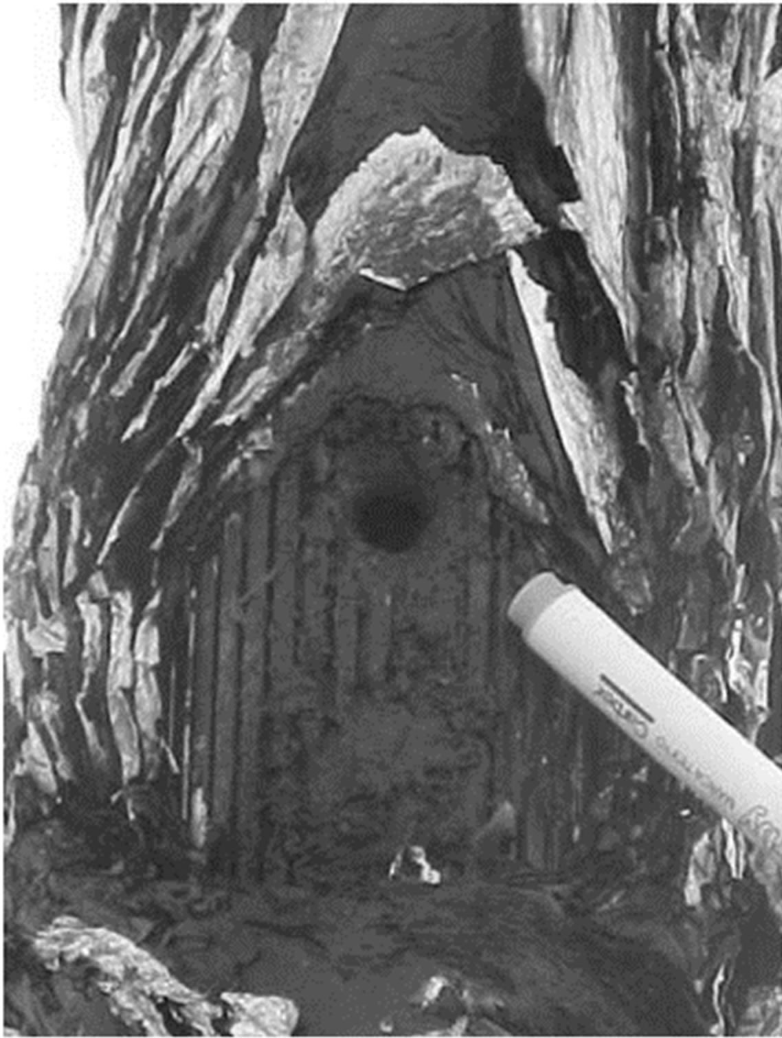
Figure 13. Bushing failure caused by degradation of it insulation.
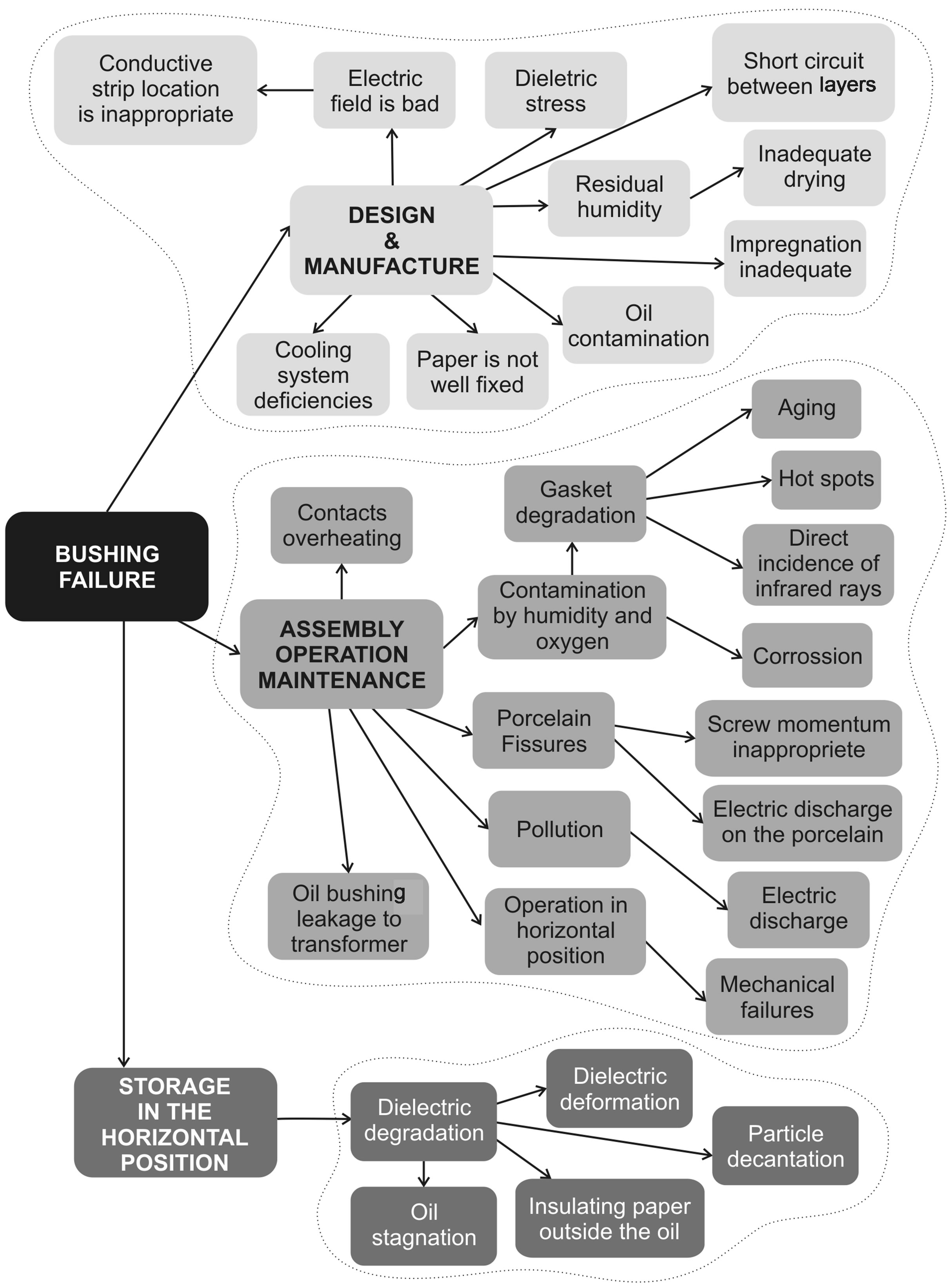
Figure 14. Probable causes of bushing failure.
The scenario represented by the path 0-1-3-5-7-9-11- 13 shows that a transformer fire could be the result of the following event sequence: after the bushing failure, it explodes and catches fire; the current required by the transformer is above its upper limit; the main tank does not withstand the internal pressure; the hole in the tank is located near the bushing; and so an ignition source is present.
The scenario represented by the path 0-2 shows that a transformer fire will not take place if the bushing does not explode after it fails.
The scenario represented by the path 0-1-4 shows that even after the bushing failure and the explosion, the transformer fire will not happen if the bushing explosion does not start a fire.
The scenario represented by the path 0-1-3-6 shows that as a result of a bushing failure there could be an explosion followed by a fire, but if the current required by the transformer is below its upper limit, the transformer fire will not take place.
The scenario represented by the path 0-1-3-5-8 shows that as a result of the bushing failure there is an explosion followed by a fire, and in addition the current required by the transformer is above it upper limit, but as the tank withstands the internal pressure, the transformer fire will not happen.
The scenario represented by the path 0-1-3-5-7-10 indicates that a transformer fire could be avoided if the hole in the tank is located far from the bushing, even if the bushing fails, explodes and catches fire as well as if either the current required by the transformer is above its upper limit or the tank fails.
The scenario represented by the path 0-1-3-5-7-9-12 indicates that the transformer fire will not happen if there are no ignition sources present, even if the bushing fails, explodes and catches fire, the current required by the transformer is above it upper limit, as well as the hole in the tank being near the bushing.
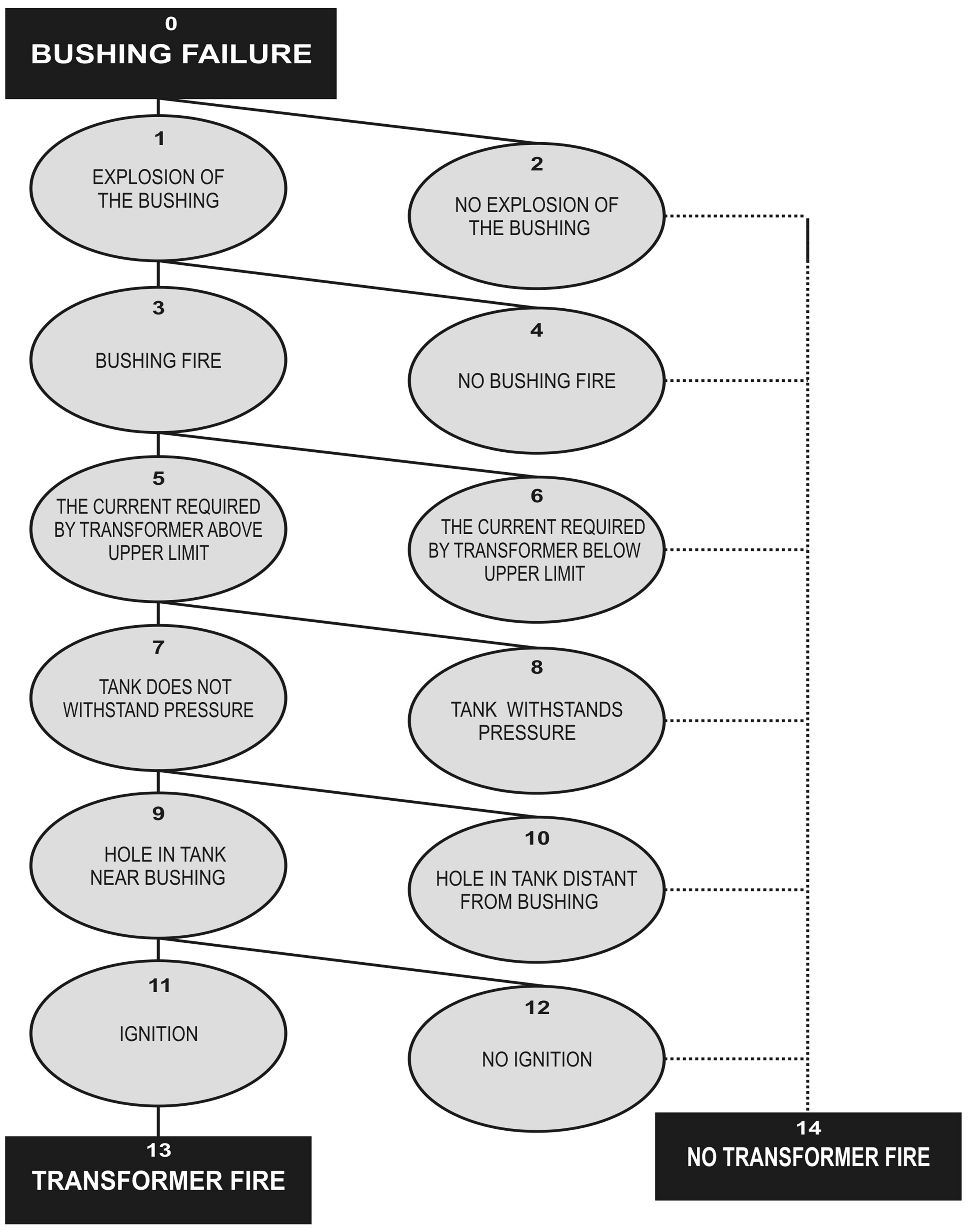
Figure 15. Bushing failure.
Power plants and substations have been around for quite some time, so ample engineering experience exists and the public is familiar with their equipment and structures (i.e. transformer, circuit breaker, transmission lines, etc.). There is also a substantial economic incentive to prevent accidents. In spite of mature technology, good management, and incentives to keep the plant or substation from blowing up, uncontrollable fire rages within them on occasion, killing operators and causing substantial losses. Traditionally, expected damages can be estimated by studying loss histories, i.e. by compiling the amounts incurred by previous events. However, loss expectancy (measured in dollars) will also depend on the substation layout and fire protection technology. The objective of the next section is to analysis the physical impact of a transformer fire on the company mission and objectives.
6. Potential Loss from Transformer Fire
Estimating the loss arising from a fire is rarely easy and can indeed verge on the impossible due to the knowledge available and technological limitations. It may appear simple to estimate the replacement costs of substation equipment or other adjacent structures which have been damaged or destroyed, but this is frequently a comparatively minor part of the total loss incurred. If a fire has been serious enough to cause a blackout, the social cost will be a significant component of the overall cost. Moreover, the Brazilian Electrical System Regulatory Agency (ANEEL) has emphasized that electrical power organizations (including power plants, transmission and distribution systems) should be heavily penalized whenever they cannot provide electricity to their consumers. ANEEL will also penalize power utilities if a transmission line, a transformer or any other piece of equipment is not available. Such penalties could compromise the company’s economic health and reputation.
The exploitation of fixed assets (such as equipment, property, etc.), human resources and information or knowledge will yield cash flow. The business will usually also draw benefit from the organization’s reputation, goodwill and physical environment. A transformer fire will have an impact on most of these elements.
A transformer fire or explosion could cause extensive damage to fixed assets of either the substation or other plants nearby as a result of the impact of thermal and blast waves. In addition, a transformer could be installed underground, such as at Itaipu Power Plant. Another important undesirable effect associated with fire, explosion and the projection of fragments is the domino effect. Under certain conditions it is possible that a transformer fire or explosion may extend to other equipment adjacent to the substation, creating a major chain accident with farreaching consequences. Attention should be given not only to the health risk, but also to the resistance of other equipment and structures to certain levels of thermal radiation.
A step-up transformer fire could put a natural gas thermoelectric power plant out of action for an extended period of time, the production loss resulting in a significant reduction in cash flow to the plant owners. This situation may be exacerbated by having to acquire alternative supplies to meet contractual commitments or by having to pay penalties such as those imposed by ANEEL, due to the unavailability of the transformer and gas turbine.
Poor mechanical design of the transformer could cause oil leakage (Figure 16), leading to oil contamination and thus to transformer fire. Additionally, a failure in the maintenance of an oil-filled transformer could result in a pool fire, spray fire or Boiling Liquid Expanding Vapor Explosion (BLEVE). The principal environmental impact would probably be the discharge of oil into the soil, which could affect the water table. In order to prevent soil contamination in the event of a major leak, rockfilled pits should collect the oil.
What are the costs of a bad reputation? While a power plant will directly suffer from a transformer fire, other companies could be adversely affected by the impaired public perception of the electricity industry as a whole. The reputation of the power generation, transmission and distribution industries will generally be established by their poorer performers.
Although establishing the actual cost of a transformer fire can be difficult, there is no doubt that there is a large bill to be paid. The organization will usually look first to their insurer for compensation, and claims settlements may well cover a large part of the losses. However, it is important to understand the nature of insurance: it will not cover the losses resulting from a poor reputation or the penalties for interruption of business.
7. Brazilian Transformer Failure versus the Globalized Economy
FURNAS Centrais Elétricas has an installed capacity of 10,050 MW. It represents 10% of all electrical energy produced in Brazil. The utility is responsible for supplying energy to the most developed region of Brazil and about 50% of Brazilian homes.
Since 1995 FURNAS has been observing an increase in the failure rate of new transformers and reactors, either during acceptance tests or in the first year of operation. Although these failures have not been catastrophic, they have resulted in equipment becoming unavailable [8]. The failure analysis pointed out deficiencies in the manufacturing process and dielectric design. For example, oil leakage from the main tank was observed to be a result of poor welding leading to the contamination of the mineral oil (Figure 16). This could have caused a transformer fire or explosion.
In other words, the investigation carried out by FURNAS showed that the main cause of failure in new transformers during operation had originated from the active components (including core, winding, etc.) and the bushing. Both the costs and the time attributed to transformer active component failure are normally much higher than those resulting from failure of intrinsic protection devices, tap changers and bushing. All failures are undesirable and a cause of concern to both the electrical power industry and transformer manufacturers. Repair cost and time depend on the affected component.
The Gross Domestic Product (GDP) of any country is proportional to its demand for electrical power. In Brazil, before the 1990s, it was only the Government that invested in the electrical power market. Moreover, the government has not been investing in power plants and distribution utilities for some time, despite electricity consumption having increased over the years. As a result, aging transformers are often overloaded. As the government could not approach the challenge of investing in the industry alone, it decided to deregulate the Brazilian market. As a result, new private utilities were created as well as Public Limited Companies (PLCs) entering the Brazilian Market.
The National Regulatory Agency of the Brazilian Electrical Power System (ANEEL) has been pushing
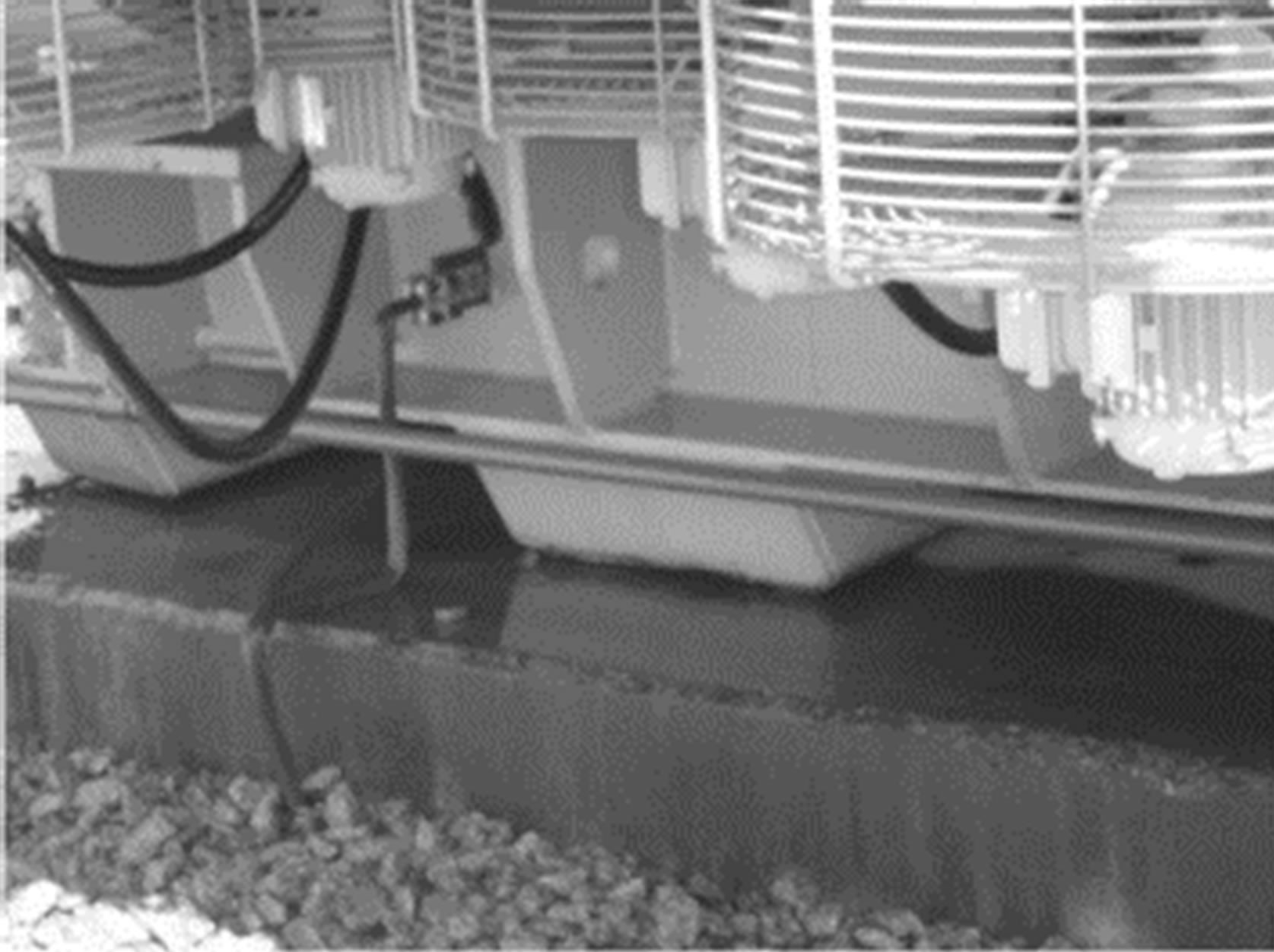
Figure 16. Oil leakage will probably cause oil contamination.
the new stakeholders to optimize the lead time for the design and construction of new facilities. On the other hand, the globalized economy has been putting pressure on manufacturers to reduce their costs. This may be achieved by reducing manufacture time through better tools or manufacturing processes, as well as sophisticated software and better materials.
Operating conditions have become more severe in recent years, and transformers have to operate in conditions of very fast transient or resonant voltage surges. These transient conditions may be the result of switching in the power system. Meanwhile, as manufacturing tools have been improving, there has been the tendency to reduce the safety factor of the transformer’s intrinsic protection, active components, tap changers or bushing to compete on the globalized market. In other words, manufacturers have been reducing transformer safety margins, as their intention is to meet only the minimum requirements of the valid standards. Moreover, there are some indications that standardized acceptance tests (type and routine tests) do not reflect operational conditions in the field.
8. Conclusions
There is a tendency in Brazil, particularly in the reports following disasters, for a detailed range of prescriptive measures to be laid down to ensure the disaster never happens again. Many of these recommendations tend to become embodied in good practice, which has helped to reduce losses. There is no doubt that the use of standards and codes in the form of good practice helps to avoid hazards of which few people are even aware. The thought process for fire-related decisions is heavily influenced by experience and interpretation of codes and standards. In other words, prescriptive fire regulations developed by consensus committees may be described as a compilation of good practices with a weak technical basis. It is important to recognize that it is standards and codes—rather than a design professional—that will assume responsibility for fire safety.
Good practice or regulatory practices in no way provide a measurement of the level of fire safety in a complex system, such as an electrical installation in a hydroelectric power plant or substation. An effective approach to fire safety is therefore needed to deal with the complexities and changes that exist in the electrical power industry.
The need to improve safety performance and, indirectly, fire prevention in Brazilian electrical power organizations, is partially driven by ANEEL. It has emphasized that the electrical power organizations (including power plants, transmission and distribution systems) should be heavily fined whenever they cannot provide electrical energy to their consumers. These fines, if applied, could compromise the organization’s economic health.
It is clear that addressing organizations’ error-inducing conditions is as important as focusing on the human and technical causes of accidents (failures). Despite these significant changes in the approach to safety and fire safety already evident in the Brazilian electrical power industry (induced by ANEEL), the implementation of performance analysis that recognizes the multifaceted approach to fire safety is still a long way off.
Fire safety still tends to be analyzed in isolation: conventional approaches to fire safety do not appear to be taking the overall system, organizational culture or the external organizational environment into account. In other words, the electrical power organizations in Brazil have a prescriptive approach to fire. They do not assess the interactions between the various subsystems, and their impact on the system’s overall performance.
9. Acknowledgements
I am deeply indebted to Medina Pena, Carlos Campos and Messias Oliveira for their wisdom and support at the final stage of developing of this study.
REFERENCES
- Duarte, et al., “Technical Report on Fire in Substations prepared by the Laboratory of Technology Risks of Federal University of Pernambuco,” RISCTEC-UFPE, Centro de Tecnologia, Cidade Universitária, Pernambuco, 1999.
- W. F. Cooper and D. A. D. Jones, “Electrical Safety Engineering,” 3rd Edition, Butterworth-Heinemann, Oxford, 1993.
- M. Medina, “Falhas em Transformadores de Potência: Uma Contribuição para Análise, Definições, Causas e Soluções,” Master Dissertation of UNIFEI, Itajubá-Brasil, 2003.
- T. Ronningen, “Internal Faults in Oil-Filled Distribution Transformer: Fault Mechanisms and Choice of Protection,” Ph.D. Dissertation, Norges Tekniske Hogskole, Trondheim, 1993.
- R. E. Benton and D. Ristuccia, “Arcing Faults Cause Transformer Failures,” Electrical World, Vol. 179, 1973, pp. 44-45.
- M. Medina, C. A. Mohallen and D. Duarte, “Failure of Power Transformer: A Contribution on Its Analysis and Reduction,” Proceedings of the Tenth Meeting of CIGRÉ for Latine America—X ERLAC, Argentina, 18-22 May 2003.
- D. Duarte, “A Performance Overview about Fire Risk Management in the Brazilian Hydroelectric Generating Plants and Transmission Network,” Journal of Loss Prevention in the Process Industries, Vol. 17, No. 1, 2004, pp. 65-75. doi:10.1016/j.jlp.2003.09.007
- G. Bastos, “An Analysis of the Increase on Transformer Failure Rate Phenomena and Measures Taken to Improve Transformers Reliability,” Proceedings of the CIGRE Bienal, Paris, 2006.