Open Journal of Antennas and Propagation
Vol.04 No.04(2016), Article ID:72240,7 pages
10.4236/ojapr.2016.44012
A Very Compact Normal Mode Multiloop Helical Antenna with Enhanced Bandwidth
Antonis A. Constantinides
Institute of Work Based Learning, Middlesex University, London, UK

Copyright © 2016 by author and Scientific Research Publishing Inc.
This work is licensed under the Creative Commons Attribution International License (CC BY 4.0).
http://creativecommons.org/licenses/by/4.0/


Received: November 3, 2016; Accepted: November 21, 2016; Published: November 24, 2016
ABSTRACT
The physical size of an antenna becomes an important characteristic when receiving signals in bands with long wavelengths. Size determines two important aspects of antenna performance; impedance and efficiency. For example, the VHF antennas installed on radio sets that intended to receive FM or the latest technology Digital Audio Broadcasting (DAB) radio signals in Bands II, III respectively. Antennas that are installed on mobile platforms (i.e. portable receivers) require a receiver that utilizes a whip telescopic antenna with adjustable length which can operate as a λ/4 monopole antenna. Whereas, non-portable applications like a deck commercial receiver has no built in antenna due to the large size of the radiator needed and so must be connected with an external antenna. This paper presents a new design of a very small size Normal Mode Multiloop Helical Antenna (NMMHA) with superior performance developed for commercial receivers operate in band II, III. The major drawback which has been overcome with this design is the very narrow bandwidth of the Normal Mode Helical Antenna, which originally was optimized to provide the minimum Voltage Standing Wave Ratio VSWR response across Band II (87.5 - 108 MHz). The NMMHA’s size allows it to be a build in block of a deck commercial receiver.
Keywords:
Normal Mode Multiloop Helical Antenna, Radio services, Impedance, Bandwidth, Gain

1. Introduction
A helical antenna is an antenna consisting of a conducting wire wound in the form of a spring [1] [2] [3] . When the Helix antenna diameter is much smaller than λ (for example, ≤0.1λ), it operates in a Normal Mode and is therefore defined as a Normal Mode Helical Antenna (NMHA). An NMHA can be mounted either vertically above a ground plane, or directly on a connector without grounding. The NMHA radiation pattern is identical to that of a monopole antenna (it is an omnidirectional side-fire radiation pattern, which is the desired radiation pattern in this application) [3] . The many advantages of the NMHA relative to the short stub or the Hertzian dipole were discussed by Kraus [3] . According to Kraus, the NMHA resonates at a much shorter physical length than does the monopole but in a very narrow bandwidth. In this respect, the axial ratio of the NMHA is given by Kraus (1988) in Equation (1) below:
 (1)
(1)
where:
C: it is the circumference
Sλ: spacing between turns in wavelengths
The three special cases pertaining to the NMHA polarization sense are given as follows:
EΦ = 0 Linear Vertical Polarization
ΕΘ = 0 Linear Horizontal Polarization
EΦ = ΕΘ Circular Polarization
Wheeler’s relation for circular polarization is given by Equation (2):
 (2)
(2)
Because a NMHA has very small dimensions, and therefore, it is an important antenna in all wireless communication engineering sectors where the physical size of the radiator plays a very significant role [4] . As a result, over the years, many researchers have attempted to increase the bandwidth of the NMHA by consisting of two strips [5] , applying the properties of a Log-Periodic arrays [6] , or constructing the antenna of two flat wire strips [7] . This paper presents a new design of a very compact Normal Mode Multiloop Helical Antenna (NMMHA) with superior performance developed to operate in the VHF band II. The antenna consists of two sections―a multiloop antenna constructed on a PCB Fr-4 substrate material and a NMHA mounted in series as will be discussed in the following sections.
2. Measured and Simulated Results of the NMHA
An NMHA depicted in Figure 1 was constructed as a part of this study in order to test its performance in real conditions and compare it with that of the quarter-wavelength monopole, the construction details of which are discussed in the next section.
The three vital parameters of the NMHA under investigation are the radiation resistance, the Voltage Standing Wave Ratio (VSWR) response and the “Gain” at the operational frequency of the commercial band FM (87.5 - 108 MHz).
The construction details of the NMHA are given below:
Diameter = 33 mm (0.01λ)
N = 9 turns
S = 4 mm
Height = 40 mm (0.013λ)
Wire Diameter = 2 mm
Pitch Angle: 7 Degrees
In order to determine the Axial Ratio (AR) of the antenna, Equation (3) can be used:
 (3)
(3)
The radiation resistance (Rs, the real part of the impedance) has been measured by the use of the VSWR analyzer MFJ 269C and the results are illustrated in Figure 2. As can be seen from the graph, at 93 MHz, the radiation resistance is close to 50'Ω. At other frequencies within the Band II, the radiation resistance becomes very low; thus, the antenna has a very narrow band response [8] [9] [10] [11] .
This is further illustrated by the VSWR response curve shown in Figure 3 which has been measured experimentally by the MFJ 269C as well, that takes into account the imaginary part of the impedance.
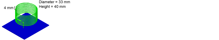
Figure 1. The normal mode helical antenna.
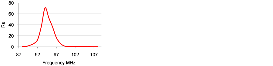
Figure 2. The radiation resistance of the NMHA.
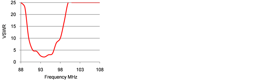
Figure 3. The VSWR response of the NMHA.
According to the graph shown in Figure 3, the VSWR response of the NMHA makes it usable in the 90 - 96 MHz range, equivalent to 5:1 VSWR. Moreover, as the VSWR response exceeds 25:1 in the beginning and at the end of the Band II, the antenna cannot be used for broadband applications. The poor VSWR response of the NMHA also affects the gain response, examined below.
3. Measured and Simulated Results of the NMHA over the Quarter Wavelength Monopole Antenna
The reception performance of the NMHA in real conditions (with “on air” existing radio services) versus a quarter-wavelength vertically polarized monopole antenna has been measured experimentally and simulated with the Excel program as presented in Table 1. In order to perform the test, each antenna was mounted at the same point on a ground plane and the results were obtained via the Advantest U3751 spectrum analyzer. According to the data reported in Table 1, the NMHA has an average gain of −4.7 dB relative to that of the quarter-wavelength monopole.
The gain ranged from −2 dB to −7 dB. The poor NMHA performance is attributed to the high VSWR response, as previously discussed.
4. Discussion―The Performance of the NMMHA
This section is dedicated to the discussion of the performance of the Normal Mode Multiloop Helical antenna (NMMHA), which was constructed with smallest physical dimensions possible. The NMMHA is shown in Figure 4. As can be seen from the image, the antenna consists of two sections―a multiloop antenna constructed on a PCB Fr-4 substrate material and a NMHA mounted in series. The longest turn’s side dimension of the planar helix is 80 mm and the total number of turns is 13.

Table 1. The gain of the NMHA versus that of the quarter-wavelength monopole antenna.

Figure 4. The normal mode multiloop helical antenna.
The NMMHA’s construction details are given below:
Diameter = 33 mm (0.011λ)
N = 5 turns
Height: = 50 mm (0.01λ)
Wire Diameter = 3 mm
Space = 4 mm
Pitch Angle: 7 Degrees
Standing alone, the NMHA incorporates 5 turns, allowing it to resonate at 101 MHz. Its height is 5 cm (0.01λ) and its diameter is 3.3 cm.
The NMMHA’s VSWR response has been measured by the MFJ 269C in the 87.5 - 110 MHz range and is presented in Figure 5. According to the experiments performed, the advantage of this topology stems from eliminating the need for a complex matching network, as only a simple 50’Ω quarter-wavelength transformer is required. According to the graph shown in Figure 5, performance of the new NMMHA is superior to that of a NMHA discussed in the previous sections. The maximum VSWR in the 87 - 110 MHz range does not exceed 5:1, whereas the average VSWR value is only 2.3:1.
In order to further confirm the superior performance of the new NMMHA, real conditions measurements by the use of the Advantest U3751 spectrum analyzer were conducted with “on air” existing radio services and the results are reported in Table 2.
According to the data presented in Table 2, the NMMHA enables an average field strength intensity of 44.1 dBuV across Band II over 34.4 dBuV of a NMHA and 39.2 dBuV of the monopole (Table 1). In this respect, the NMMHA antenna presented in this section, despite having the smallest possible physical size, has been confirmed to exhibit the greatest efficiency when compared to all other antennae examined in this work.
5. Conclusion
The Normal Mode Multiloop Helical Antenna has been demonstrated in this research is capable of providing excellent specifications as a stand-alone antenna in VHF Band. The novelty of the modified NMHA stems from its small dimensions relative to other
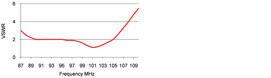
Figure 5. The VSWR response of the NMMHA.
Table 2. Real conditions field strength measurements of the modified NMHA.
small antennas, such as the Herzian dipole or the short stub, without requiring complicate matching networks with higher efficiency. As a result, it would be highly important for future research pertaining to the NMHA to apply this topology across Band I or in lower frequency applications, i.e. the HF band where antennas must be constructed with large physical dimensions.
Cite this paper
Constantinides, A.A. (2016) A Very Compact Normal Mode Multiloop Helical Antenna with Enhanced Bandwidth. Open Journal of Antennas and Propagation, 4, 159-165. http://dx.doi.org/10.4236/ojapr.2016.44012
References
- 1. Kraus, J. (1949) The Helical Antenna. Proceedings of the IRE, 37, 263-272.
https://doi.org/10.1109/jrproc.1949.231279 - 2. Abd-Alhameed, R. and Excell, P. (1999) Analysis of a Normal-Mode Helical Antenna Including Non-Uniform Wire Surface Current Effects. IEE Proceedings of Microwaves, Antennas and Propagation, 146, 1.
- 3. Kraus, J. (1988) Antennas. McGraw-Hill, New York.
- 4. Huang, J.X. and Yu, Y. (2014) An Electrically Small Normal-Mode Helical Antenna with Capacitive Coupling Feed. The 8th European Conference on Antennas and Propagation (EuCAP 2014), The Hague, 2915-2917.
- 5. Noguchi, K., Mizusawa, M., Yamaguchi, T., Okumura, Y. and Betsudan, S. (2000) Increasing the Bandwidth of a Small Meander-Line Antenna Consisting of Two Strips. Electronics and Communications in Japan (Part II: Electronics), 83, 35-43.
- 6. Chatterjee, J. and Roy, M. (1968) Helical Log-Periodic Array. IEEE Transactions on Antennas and Propagation, 16, 592-593.
https://doi.org/10.1109/TAP.1968.1139249 - 7. Noguchi, K., Betsudan, S., Katagi, T. and Mizusawa, M. (2003) A Compact Broad-Band Helical Antenna with Two-Wire Helix. IEEE Transactions on Antennas and Propagation, 51, 2176-2181.
https://doi.org/10.1109/TAP.2003.816358 - 8. Shackelford, A., Lee, K.-F. and Luk, K. (2003) Design of Small-Size Wide-Bandwidth Microstrip-Patch Antennas. IEEE Antennas and Propagation Magazine, 45, 75-83.
https://doi.org/10.1109/MAP.2003.1189652 - 9. Mounich, G. and Littmann, B. (1998) Helical Antenna and Spiral Antenna with Fast Switch Selection of the Polarisation Sense. Electronics Letters, 26, 1918.
https://doi.org/10.1049/el:19901235 - 10. Godara, L. (2002) Handbook of Antennas in Wireless Communications. CRC Press, Boca Raton.
- 11. Weiner, M. (2003) Monopoantennas. Marcel Dekker, New York.