Open Journal of Geology
Vol.3 No.2(2013), Article ID:30189,5 pages DOI:10.4236/ojg.2013.32006
Construction of Subsurface Geological Structures Using a Drilling Database: A Case Study for an Intra-Arc Basin, the Osaka Plain, Southwest Japan
1Graduate School of Science and Engineering, Doshisha University, Kyoto, Japan
2Faculty of Science and Engineering, Doshisha University, Kyoto, Japan
Email: eum1902@mail4.doshisha.ac.jp
Copyright © 2013 Minao Sakurai, Fujio Masuda. This is an open access article distributed under the Creative Commons Attribution License, which permits unrestricted use, distribution, and reproduction in any medium, provided the original work is properly cited.
Received February 5, 2013; revised March 8, 2013; accepted April 8, 2013
Keywords: Intra-Arc Basin; Subsurface Geological Structure; Basement Structure; Drilling Database
ABSTRACT
Subsurface geological cross sections of 0 - 200 m depth were constructed using a dense drilling database of the Osaka Plain in the intra-arc Osaka Basin of the Japan island arc, an active plate margin. The cross sections revealed the subsurface geological structures and the geometry of folding and faulting in the basin. The comparison between the constructed subsurface cross sections and the seismic sections of the basement and basin fills at a depth of 1500 - 2000 m showed that the basement and shallow subsurface structures are similar; however, the shallow cross sections were of higher resolution than the deep seismic profiles.
1. Introduction
A drilling database is a structured collection of past drillling data, and it has been mainly used as a tool in engineering geology. The drilling database includes information regarding lithofacies such as gravel, sand, silt and clay, and the strength of foundation beds. Generally, it does not include information regarding the specific grain size or age, parameters that are typically used in academic studies. The drilling database of the Osaka Plain includes about 50,000 drilling log data points and provides a detailed picture of the lithofacies of the subsurface.
The Osaka Plain (Osaka sedimentary basin) is one of the intra-arc basins in the Japan island arc. The Japan island arc is at an active plate margin, and several intraarc basins have formed because of tectonic movements during the Quaternary. In these intra-arc basins, soft Quaternary sediments accumulated because of basin subsidence and reached a maximum thickness of about 2000 m. In the Osaka Plain, the shallow subsurface geology down to 50 m depth is characterized by faults and flexures formed during the Quaternary [1].
In this study, we created 0 - 200 m deep geological cross sections of the subsurface of the Osaka Plain using a drilling database and compared the geological structures in these cross sections with the 1500 - 2000 m deep basement structures. We found that the basement and shallow subsurface geological structures are similar suggesting that we can use shallow cross sections from drillling databases to understand the basement structures.
2. Geological Setting of the Study Area
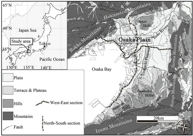
The Osaka Plain is surrounded by 300 - 1100 m high mountains that consist of basement rocks, and in the central part of the plain, there is a characteristically elongate structural high called the Uemachi Plateau characteristically elongated from the southern mountains to the north (Figure 1). A delta plain with an elevation of 10 m or less develops in the west of the Uemachi Plateau, and a flat plain dominates the area east of the Uemachi Plateau. In contrast, in the north and south of the Osaka Plain, terraces and hills ranging in elevation between 30 and 150 m develop near the mountains. There is an active fault at the boundary of the mountains and the plain along the western side of the Uemachi Plateau.
The subsurface of the Osaka Plain consists of Quarternary sediments ranging from 1500 to 2000 m in thickness [2,3]. The upper part of the strata is interbedded with marine clays that represent inner bay floor deposits when the highstand is controlled by eustatic change [4]. The

Figure 1. Location of the study area and the lines of cross sections (The map was compiled from the geological map of Japan 1:200,000 “Kyoto-Osaka” [10] and “Wakayama” [11]).
strata near the active faults show drag-deform features under the influence of fault activity [1,3,5].
The Osaka sedimentary basin began to form about 3 Ma ago, and the formation of the basin is associated with mountain uplift and basin subsidence because of the west-east compression in southwestern Japan [6,7]. The rate of subsidence was such that the central part of the basin is higher than the margins. The subsidence rate of the basin slowed 0.4 - 0.5 Ma ago, while the uplift rate of the mountains increased [3]. The Osaka sedimentary basin is divided into two major basement rock blocks by the north-south Uemachi fault along the western side of the Uemachi Plateau. The western block is tilting toward the south, and the eastern block is tilting toward the southeast [8]. The estimated rate of the Uemachi fault displacement is 0.7 - 0.2 m/ky for the last 1.2 Ma [3].
Recently, many seismic reflection and gravity surveys have been performed in the Osaka Plain, and as a result, the distribution and depth of the basement structures of the basin were revealed [5,9]. These surveys were triggered by the enormous disaster caused by the 1995 earthquake in the south Hyogo Prefecture and aimed to provide a more accurate picture of the seismic wave propagation and features in the Osaka sedimentary basin.
3. Data and Methodology
We used the drilling database that has been operated by the Kansai Geoinformatics Network [12] and includes about 50,000 drilling log data points for civil engineering projects. The database only includes information on lithofacies such as gravel, sand, silt and clay, N-value, and other geotechnical engineering data. Its usefulness lies in the large number of subsurface geological data that it contains.
We used the database to create two cross sections along the west-east and north-south directions. These go through the OD-1 drilling core site that represents the typical lithostratigraphy of the subsurface of the Osaka Plain [2]. The cross-sectional lines are sinuous because the drilling data fall along linear construction sites such as highways.
The boundaries of the lithofacies were traced in the cross sections on the basis of sedimentological concepts. More specifically, the base of the marine clay beds with a transgressive erosional surface (i.e., ravinement surface) [13] is shown by straight lines; the top of marine clay beds overlaid by a progressive delta or fan is shown with lightning-stroke-type “shazam lines” [14]; the base of gravel beds with a sequence boundary is shown by valley-shaped curve lines, and dashed lines mark uncertain boundaries.
4. Results and Discussion
4.1. The Features of Geological Structure in the Cross Sections
4.1.1. West–East Section
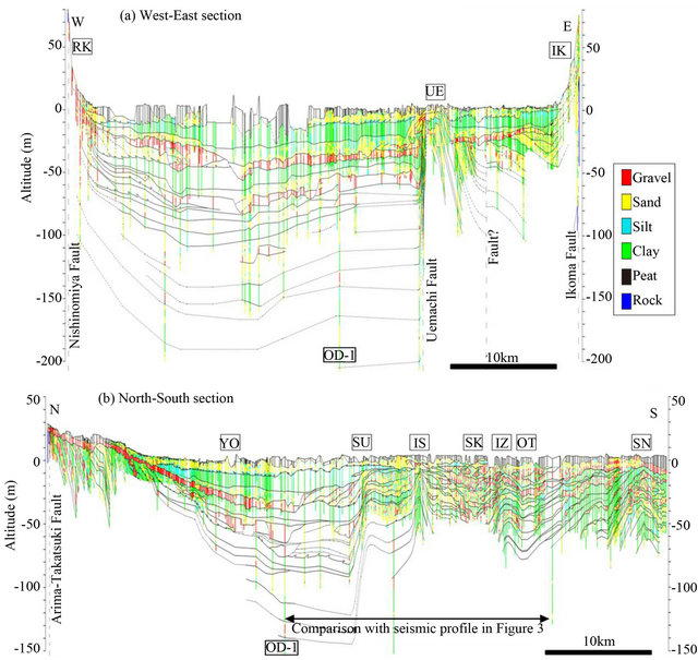
In the west-east section, there is flexure in the northern Uemachi Plateau, and in both sides of the flexure, there are basin-shaped structures (Figure 2(a)), and the major structural gap in the western margin of this section is the Uemachi fault. The eastern area of the flexure is the limb of the flexure with an apparent eastward dip of 1˚ - 2˚, while the eastward dipping 125-ka marine clay bed suddenly changes westward near the Ikoma fault at the Ikoma Mountains. There is minor fault uplift in the east-

Figure 2. Subsurface geological cross sections of the Osaka Plain. The location of the cross sections is shown in Figure 1. (a) West-East section. (b) North-South section. RK: Rokko Mountains; UE: northern Uemachi Plateau; IK: Ikoma Mountains; YO: Yodo River; SU: Suminoe flexure; IS: Ishizu anticline; SK: Sukematsu syncline; IZ: Izumiotsuko anticline; OT: Otsugawa syncline; SN: Sanoko anticline; OD-1: OD-1 drilling core site.
ern area at the east limb of the flexure. The western area of the flexure is the relatively the broadest part of the basin with horizontal strata dipping southeastward 1˚ - 2˚ at the Nishinomiya fault near the Rokko Mountains.
4.1.2. North-South Section
The north-south section is characterized by an asymmetrical basin-shaped structure with subsided the central area (Figure 2(b)). A southward-dipping monocline structure with a 2˚ apparent dip is seen from the northern end to the Yodo River and an asymmetrical deep trough is present from the Yodo River to the Suminoe flexure [15]. The northern margin at the Suminoe flexure is a northward-dipping structural gap with an apparent 4˚ dip. From the Suminoe flexure to the southern end of this section, the strata dip northward (about 0.1˚ dip) with alternating flexures and folds referred to as the Suminoe flexure, the Ishizu anticline, the Sukematsu syncline, the Izumiotsuko anticline, the Otsugawa syncline, and the Sanoko anticline [16]. Especially, the Suminoe flexure, Ishizu anticline, and Sukematsu syncline are major structural gaps.
4.2. Comparison between the Subsurface Geological Sections and Seismic Profiles
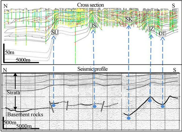
We compared the seismic profiles from seismic reflection surveys and the subsurface geological sections from the drilling database. In general, their structures matched; however, the subsurface geological structures are more detailed than the seismic profile structures (Figure 3). The comparison concerns the southern part of the northsouth section. The seismic profile shows faults and folds even at a depth of 1500 - 2000 m in the basement [5,17]. The location of the anticlines and synclines in the cross section generally agrees with the location of the basement structures in the seismic profile. In the latter, the steeply dipping structures at the northern margin of the Suminoe flexure and the southern margin of the Ishizu anticline in the cross section are shown as faults, and the sinuously deformed Izumiotsuko anticline and Otsugawa syncline are shown as folds. Therefore, it is not clear from the seismic profile whether the structural gaps at the northern margin of the Ishizu anticline, Sukematsu syncline, and Izumiotsuko anticline in the cross section are basement faults.

Figure 3. Comparison between cross section and seismic profile. The location of the section is shown in Figure 2. The seismic profile is from the Kansai Geoinformatics Research committee (2007) [5]. SU, IS, SK, IZ, OT: see legend in Figure 2.
The matching of the subsurface geological structures from the drilling database and the deep basement structures makes it possible to differentiate the basement structures on the basis of detailed analysis of the subsurface geological structures. The subsurface geological sections from the drilling database show geological structures that are not discerned in the seismic profile. Apparently, the subsurface geological section is of higher resolution than the seismic profile. Furthermore, because sections based on the drilling database can be created for every direction, they can be used to analyze three-dimensional geological structures more easily. Thus, the subsurface geological structures can contribute to the analysis of basement structures and help reconstruct the evolution of the intra-arc basins.
5. Conclusions
In this study, we created subsurface geological cross sections of the Osaka Plain, an intra-arc basin, by using a drilling database. We analyzed the geological structures in these sections and compared them with the deep basement structures; the following are our conclusions:
1) The subsurface geological structures from the drilling database and the deep basement structures generally match. Therefore, it is possible to understand the basement structures through detailed analysis of the subsurface geological structures.
2) The subsurface geological sections from the drilling database show geological structures that are not clearly discerned in the seismic profile. Therefore, the subsurface geological section is of higher resolution than the seismic profile.
3) The structural features in the west-east section are a flexure in the northern Uemachi Plateau, which is the structural high of the inner basin, the Uemachi fault that is a major structural gap at the western margin of the flexure, and the basin-shaped structure on both sides of the flexure.
4) The features in the north–south section are the southward-dipping monocline structure in the northern part, the asymmetrical basin-shaped structure in the central part, and the northward-dipping flexure and fold in the south.
6. Acknowledgements
We are grateful to the Kansai Geoinformatics Network for providing the Kansai Geo Information database.
REFERENCES
- M. Furutani, “Upper Pleistocene Series of the Western Osaka Plain,” Journal of Geological Society of Japan, Vol. 84, No. 7, 1978, pp. 341-358. doi:10.5575/geosoc.84.341
- N. Ikebe, J. Iwatsu and J. Takenaka, “Quaternary Geology of Osaka with Special Reference to Land Subsidence,” Journal of Geosciences, Osaka City University, Vol. 13, 1970, pp. 39-98.
- M. Uchiyama, M. Mitamura and S. Yoshikawa, “Displacement Rate of the Uemachi Fault and Basement Block Movements of the Osaka Plain, Southwest Japan,” Journal of Geological Society of Japan, Vol. 107, No. 3, 2001, pp. 228-236. doi:10.5575/geosoc.107.228
- F. Masuda and M. Ito, “Contributions to Sequence Stratigraphy from the Quaternary Studies in Japan,” The Quaernary Research, Vol. 38, No. 3, 1999, pp. 184-193.
- Kansai Geoinformatics Research Committee, “New Kansai Ground-Osaka Plain to Osaka Bay,” Kansai Geoinformatics Network, Osaka, 2007.
- N. Ikebe, “Cenozoic Geohistory of Japan,” Proceedings of the 8th Pacific Science Congress, Vol. 2, 1956, pp. 446- 456.
- K. Huzita, “Rokko Movements and Its Appearance-Intersecting Structural Patterns of Southwest Japan and Quaternary Crustal Movements,” The Quaternary Research, Vol. 7, No. 4, 1968. pp. 248-260.
- M. Mitamura and S. Yoshikawa, “Late Pleistocene Movement Basement Blocks in the Osaka Sedimentary Basin,” Earth Science, Vol. 51, No. 1, 1997, pp. 8-14.
- N. Inoue and K. Nakagawa, “Modeling of the Underground Structure in the Osaka Sedimentary Basin Based on Geological Interpretation of Gravity Anomalies and Seismic Profiles,” Journal of Geosciences, Osaka City University, Vol. 43, 2000, pp. 97-110.
- K. Kawada, M. Miyamura and F. Yoshida, “Geological Map of Japan 1:200,000, Kyoto-Osaka,” 1985.
- C. Kurimoto, H. Makimoto, F. Yoshida, Y. Takahashi and M. Komazawa, “Geological Map of Japan 1:200,000, Wakayama,” 1998.
- Kansai Geoinformatics Network, “Kansai Geoinformatics Database CD-ROM,” 2011.
- D. Nummedal and D. J. P. Swift, “Transgressive stratigraphy at Sequence-Bounding Unconformities: Some Principles Derived from Holocene and Cretaceous Example,” In: D. Nummedal, O. H. Pilkey and S. D. Howard, Eds., Sea Level Fluctuation and Coastal Evolution. SEPM Special Publication, Vol. 41, 1987, pp. 241-260. doi:10.2110/pec.87.41.0241
- M. R. Gani and J. P. Bhattacharya, “Lithostratigraphy versus Chronostratigrahphy in Correlations of Quaternary Deltas: Application of Bedding Correlation,” In: G. Giosan and J. P. Bhattacharya, Eds., River Deltas-Concepts, Models, and Examples. SEPM Special Publication, Vol. 83, 2005, pp. 31-47.
- M. Mitamura, N. Matsuyama, K. Nakagawa, K. Yamamoto and S. Suwa, “Stratigraphy and Subsurface Structure of Holocene Deposits around Uemachi Upland in the Central Osaka Plain,” Journal of Geosciences, Osaka City University, Vol. 37, 1994, pp. 183-212.
- Hanshin Expressway Government Corporation, “The Feature of Geology and Geotechnology in the Osaka Bay Area (Osaka City-Izumisano City),” Osaka Construction Department of Hanshin Expressway Government Corporation, 1991.
- Osaka Prefecture, “Investigation Report of the Subsurface Geological Structure in the Osaka Plain: The Fiscal Year of 2003,” 2004.

