Optics and Photonics Journal
Vol.3 No.6(2013), Article ID:38285,5 pages DOI:10.4236/opj.2013.36052
Interferometry Analysis of Cellophane Birefringence
1Department of Physics, Kenyatta University, Nairobi, Kenya
2Department of Physics, Jomo Kenyatta University of Agriculture & Technology, Nairobi, Kenya
Email: grurimo@gmail.com
Copyright © 2013 Dickson M. Kinyua et al. This is an open access article distributed under the Creative Commons Attribution License, which permits unrestricted use, distribution, and reproduction in any medium, provided the original work is properly cited.
Received August 3, 2013; revised September 4, 2013; accepted September 28, 2013
Keywords: Cellophane Sheet; Birefrigence; Interferrogram; Polarization
ABSTRACT
This paper reports on a simple approach of determining the ability of a transparent material, such as cellophane to rotate the direction of polarization of a light beam. In order to determine the birefringence of such a material, a Mach-Zehnder interferometer is used to generate interference patterns when the cellophane sheet is mounted on one arm such as to intercept a portion of the laser beam. The recorded interferograms show a phase shift which is calculated to be 0.98π radians. By rotating the cellophane sheet on the object beam, the fringe separation is measured for different angles and the values used to calculate the ordinary and extraordinary refractive indices as 1.4721 ± 0.0002 and 1.4680 ± 0.0002 respectively at 632.8 nm wavelength. A surface error of approximately λ/16 (peak to valley) is measured from the recorded interferograms. Because of its sufficient birefringence and small thickness of 24 µm, cellophane can be used to fabricate special polarization pupil masks by cutting and aligning different cellophane structures appropriately.
1. Introduction
Cellophane is a thin, flexible, transparent material made from wood pulp and used as a moisture proof wrapping. Its impermeability to air, oils, greases, and bacteria makes it useful for food packaging. It is still used today for packaging a variety of food items as well as in industrial applications like a base for self-adhesive tapes. There has been some resurgence of interest on cellophane sheet due to its behavior as a half-wave plate [1]. The sheet has been used to fabricate a complementary cellophane optic gate for 3D iPad display [2] and to study the effect on polarized light [3].
During its manufacturing process, an alkaline solution of cellulose fibers (usually wood or cotton) known as viscose is extended through a narrow slit of an acid bath. The acid regenerates the cellulose, forming a film. Further treatment, such as washing and bleaching, yields cellophane. Due to the unidirectional stress during the extrusion process, the cellophane is an anisotropic material and behaves like a calcite crystal. The refractive index ny of the cellophane along the longer dimension of the rolled cellophane is different from the refractive index nx in the direction of the shorter dimension (x-direction). As a result, a light wave component polarized in the x-direction propagates through the medium faster than the component polarized in the y-direction. After transmission through such a medium, a phase difference arises between these two light wave components. This behavior exhibited by the cellophane sheet strongly points to the fact that it can be used as a half-wave plate. The sheet shows superior behavior when used for rotating the direction of polarization and as a result has been used to convert a laptop computer screen into a three dimensional display [4]. The film has been shown to have retarder properties for a wide spectrum of wavelengths 400 nm to 780 nm [5]. Wave plates operate by imparting unequal phase shift between the two polarized components of an incident light beam. On emergence, the phase difference  between the two beams is given by:
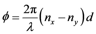 (1)
(1)
where  is wavelength of the incident light, nx and ny are the refractive indices of the fast and slow axes respectively and d is the thickness of the wave plate [6-8]. If such a phase difference is equivalent to π radians, the material is a half-wave plate (HWP). Such a material will rotate an incident beam to twice the angle between the incident beam and the optical axis [9-11].
In the next sections, it will be demonstrated that, the ability of a transparent material to rotate polarization of an incident beam can be deduced by measuring the optical power modulation of the sand p-polarized components. Further, a Mach-Zehnder interferometer is used to measure the birefringence due to a transparent sheet such as cellophane.
2. Methodology
A simple optical system is designed to measure the modulated light beam as the cellophane sheet is being rotated. A comparison with a commercial HWP is done. Further, a Mach-Zehnder Interferometer is used to study the birefringence of a cellophane sheet.
2.1. Measurement of Modulated Light Beam Intensity
The schematic set-up used for this study is shown in Figure 1. A linearly polarized light beam from a He-Ne Laser is spatially filtered and then collimated. The collimated beam is passed through a polarizing beam splitter cube (PBS), which separates the P and S-polarized waves. The cellophane sheet sample was mounted on a rotatable holder calibrated in degrees and placed on the beam path before the PBS (Figure 1). In order to investigate the phase retarding property of the cellophane sheet the mounted sample was rotated in steps of 5˚ and the power of one of the polarized waves from PBS measured. The power meter was interfaced to a computer for display and recording of data. A commercial half wave plate at 633 nm was also investigated for comparison with the cellophane sheet sample. This experiment produced the result presented in Figure 3.
2.2. Measurement of Cellophane Birefringence
To further investigate the birefringence properties of the
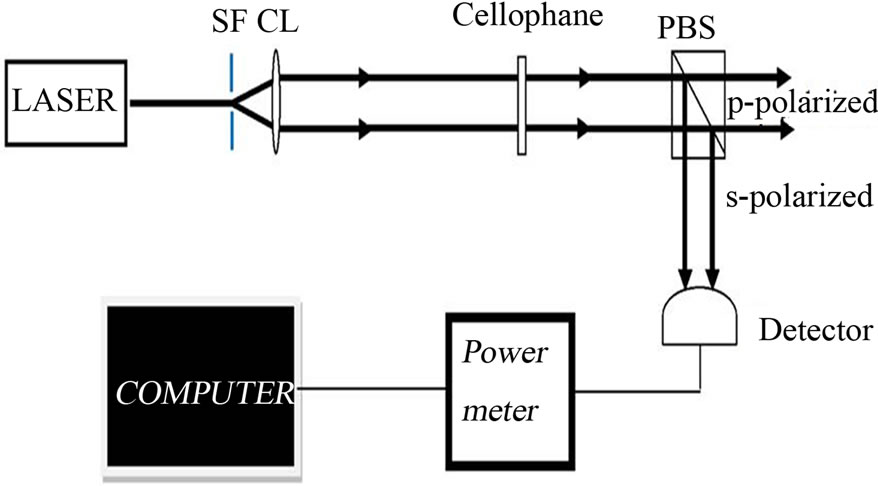
Figure 1. Set-up to investigate the birefringence of the cellophane sheet. A correct choice of the cellophane sample rotated the direction of the linearly polarized beam giving rise to varying pand s-polarized beam powers.
cellophane sheet, a Mach-Zehnder interferometer set-up was used as shown in Figure 2. The Laser beam was spatially filtered and collimated by the collimating lens CL. It was then split by beam splitter BS1 to form Beam 1 and Beam 2. Beam 1 interacted with the cellophane sample before being reflected by M1 to BS2 where it interferes with the Beam 2. As a result Beam 1 is referred to as the object beam because it carries information about the sample whereas Beam 2 is the reference beam. The cellophane sample in Figure 2 was half-way sandwiched between two glass plates for support and the combination mounted on a calibrated rotatable mount. The mounted cellophane sample was such that, the zero mark of the rotatable holder coincided with the direction of its length. It is this mounted cellophane sample that was placed on the path of Beam 1 and the resulting interference pattern in the set-up recorded.
The patterns were projected on the CCD-Camera interfaced to a computer for the display and recording of the inteferograms. The results of this experiment are presented in Figure 4. To determine the refractive index of the cellophane sample, the orthogonal directions defining the fast and slow axes must be known. To accomplish this, the cellophane sample was placed on the path of Beam 1 of Figure 2 and rotated as the fringes were recorded.
The refractive indices were determined by measuring the spacing between adjacent fringes  and
and  for two sets of interference patterns recorded at different angles of the mounted cellophane sheet. Equation (2) was used for evaluating the extraordinary and ordinary refractive indices nx and ny respectively.
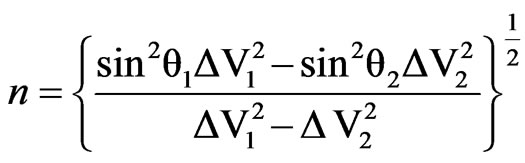 (2)
(2)
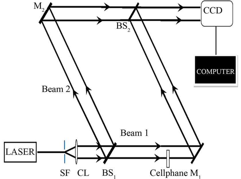
Figure 2. Set-up to record the interference pattern with the cellophane mounted so as to intercept a portion of beam 1. The same set-up is used to determine the fringe spacing for different angles of the cellophane sheet. SF is the spatial filter, CL is collimator lens, BS1 and BS2 are the beam splitters and M1 and M2 are reflecting mirrors.
where n is the refractive index and  is the incident angle [12].
3. Experimental Results and Discussion
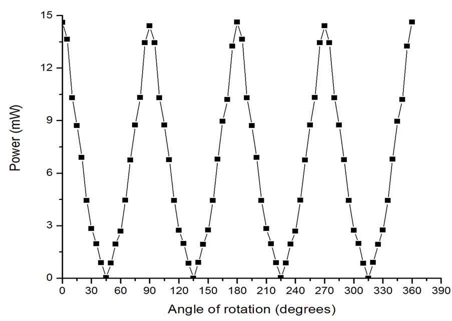
A series of experiments were performed to investigate the ability of a cellophane sheet to perform as a purpose built half-wave plate (HWP). The graph presented in Figure 3 indicates the power variation from the polarizing beam splitter (PBS) as the cellophane sample and commercial HWP were rotated. This was achieved using the setup in Figure 1.
The graph shows power in milliwatts at each of the data points corresponding to an angular position of the cellophane sample and HWP. The cellophane sample compares very well to an ideal HWP in rotating the direction of polarization of the laser beam. The power is maximum when the polarization direction of the beam emerging from the cellophane sheet is parallel to the direction of an s-polarized wave of the PBS and minimum
 (a)
(a)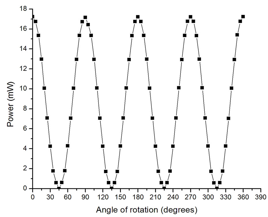 (b)
(b)
Figure 3. A plot of the measured optical power values versus angles of rotation for cellophane sheet (a) and a commercial HWP (b).
when orthogonal. It is also clear from the graph in Figure 3, that the commercial HWP gives higher maximum and lower minimum power levels. This is due to the anti-reflection coating possessed by the commercial HWP. If we define the ratio between the maximum and minimum power as the extinction ratio; the extinction ratio of the cellophane sheet is approximately 470 and 1770 for commercial HWP.
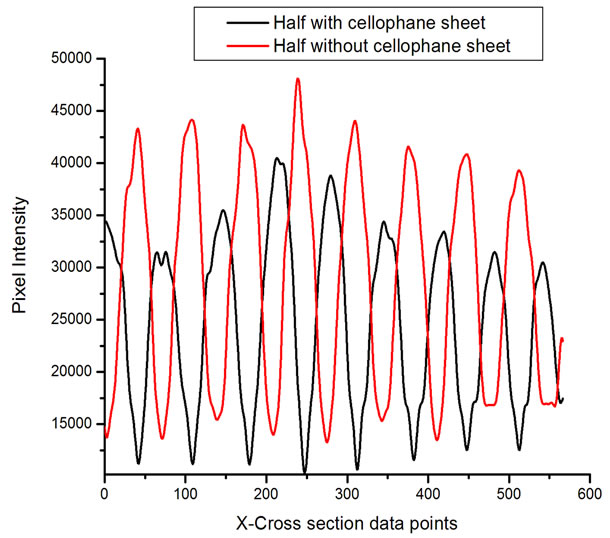
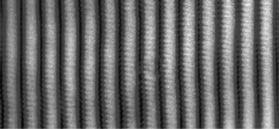
Figure 4 shows the recorded fringes in gray scale when the cellophane sheet is mounted such as to intercept a portion of beam 1 in Figure 2. The interferogram shows a discontinuity at the point where the cellophane sample ends. This discontinuity is rather not straight because of an irregular cut of the cellophane sample. The interferogram clearly shows a phase shift which causes a dark fringe to coincide with a bright fringe at the opposite sides of the boundary. Figures 5(a) and (b) shows the pixel intensity plots along the cross-sections (i) and (ii) of Figure 4 respectively. The fitted waveform is included as well. Using equation 1 and the parameters experimentally obtained, a calculated phase shift of 0.98π radians was obtained. To determine the directions defining the fast and slow axis, a comparison of the cellophane sheet with a commercial HWP (which has both the fast and slow axis defined) was done.
For fast and slow axis the direction of polarization is only altered in such a way that the two beams remain parallel to each other and therefore make maximum contribution to interference. When mounted 450 from the fast axis the polarizations of the object and reference beams are orthogonal to each other. Their contribution to interference is zero. Figure 6 shows the interference patterns and their corresponding pixel intensity profiles when the X-cross section pixel data point
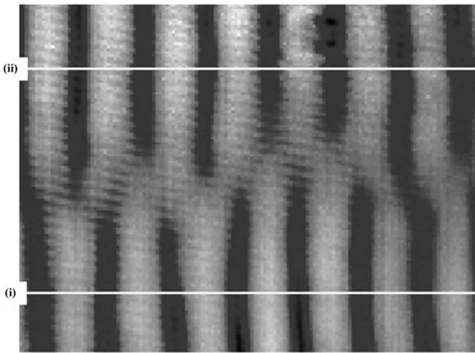
Figure 4. The interference pattern of the cellophane sheet half way mounted, where (i) Indicates a cross section on part with cellophane and (ii) Indicates a cross section on part with no cellophane. An irregular cellophane boundary can be seen due to an irregular cut.
 (a)
(a)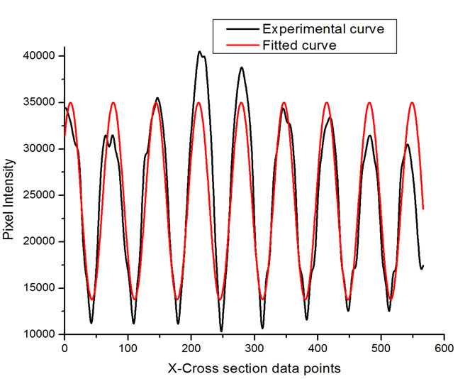 (b)
(b)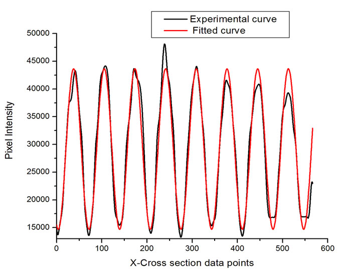 (c)
(c)
Figure 5. (a) The graph of the intensity profile on the half without cellophane and fitted curve; (b) the intensity profile on the half with cellophane and fitted curve; (c) graph of intensity profiles from (a) and (b) plotted together. The graph clearly shows a phase shift where the maximum of one profile coincides with the minimum of the other. Lower power is recorded on part with cellophane sheet because of losses due to diffuse reflection on cellophane surface.
 (a)
(a)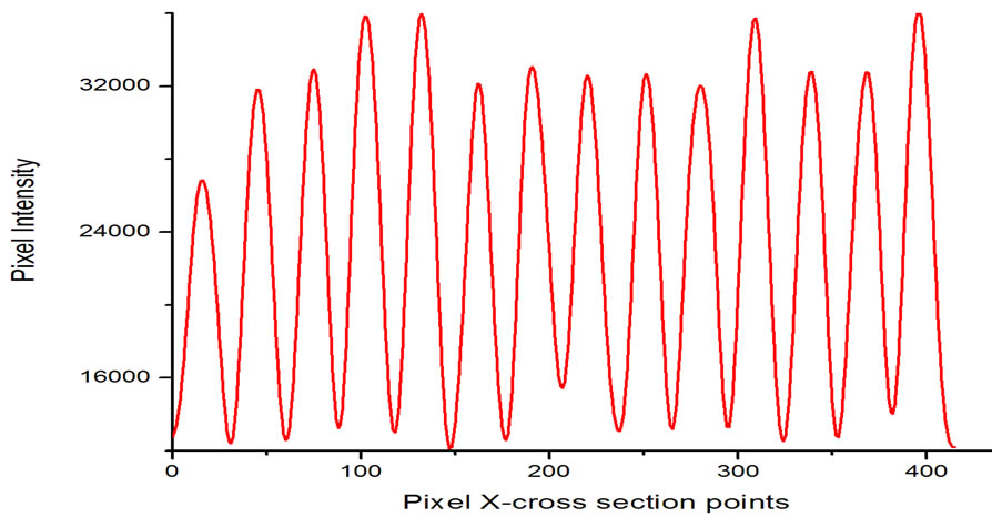 (b)
(b)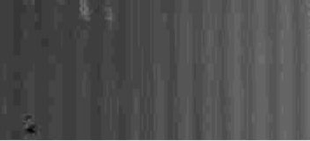 (c)
(c)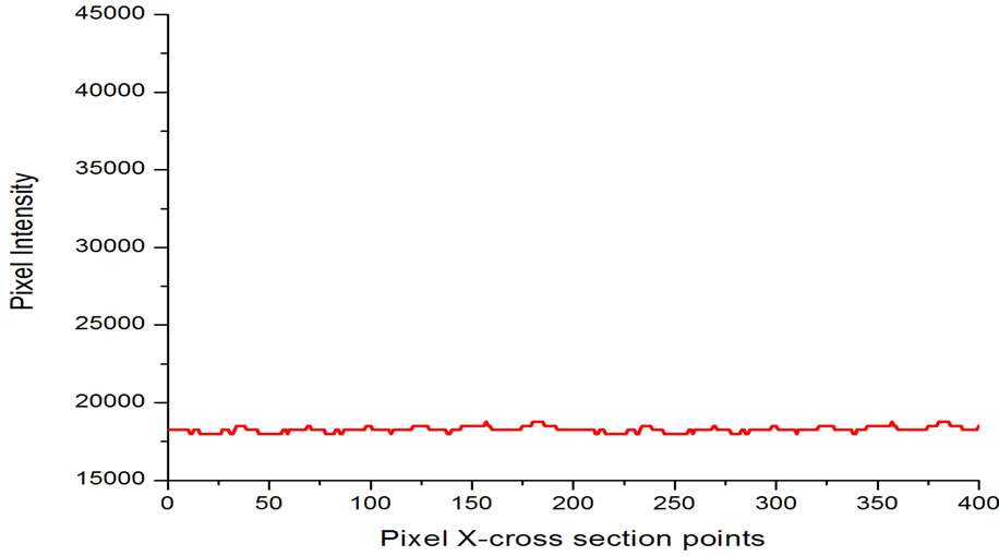 (d)
(d)
Figure 6. (a) Fringe pattern recorded with cellophane mounted along its length; (b) The corresponding pixel intensity graph for (a); (c) Fringe pattern recorded with cellophane mounted 45˚ relative to its long dimension; (d) The pixel intensity plot for (c).
polarizations of the interfering beams are parallel and orthogonal respectively. The cellophane sheet showed maximum fringe contrast along the length axis and along the width axis (Figure 6(a)). This corresponds to the polarization of the object and the reference beams being parallel to each other at the point of interference.
In order to determine the fast and slow axis, interferograms were recorded for angles of incidence adjacent to the two axes. The recorded interferograms were further analyzed to obtain the fringe separation in each case. Using the measured values and applying Equation (2) for the fringes recorded at different angles of incidence adjacent to both axes yields refractive index values of 1.4680 ± 0.0002 and 1.4721 ± 0.0002. The fast axis has the lower value of refractive index and is along the length of the cellophane sheet. The slow axis is along the width of the sheet and has the higher value of the refractive index. Therefore the ordinary and extraordinary refractive indices for the cellophane sample at 632.8 nm wavelength are given as 1.4680 ± 0.0002 and 1.4721 ± 0.0002 respectively. From the refractive index obtained and thickness of 24 µm, it becomes possible to calculate the phase difference. Applying Equation (1) results to a phase difference of 0.977031 radians. A peak to valley surface quality error of 0.063λ (approximately λ/16) was calculated using the Atmosfringe optical software.
4. Conclusions
Interferometry analysis of a cellophane sample has been accomplished using a Mach-Zehnder interferometer (MZI) setup. Using the setup, it was established that a right choice of cellophane sheet possessed sufficient birefringence to perform as a half wave retarder. The fast and the slow axis of the sample were determined to be along the length and width of the sample respectively. The calculated values of the ordinary and extraordinary refractive indices were 1.4680 ± 0.0002 and 1.4721 ± 0.0002 respectively which gave a birefringence value of 0.0041 ± 0.0003 with the error being calculated as the square root of the sum of the squares of the errors.
A phase shift of 0.98π radians was evaluated from interferograms recorded when mounting the cellophane sample on one arm of the MZI as to intercept a portion of the laser beam. The measured phase shift value compares very well with that of a purpose built half wave plate. Its retardation is 98% that of an ideal half wave retarder; hence a correct choice of cellophane is good enough to perform as a half wave retarder. A surface quality error of approximately λ/16 (peak to valley) was measured by analyzing the recorded interferograms. Consequently, the cellophane sheet provides an alternative to commercial half wave plates especially in applications that are not critical to surface aberrations or the beam can be spatially filtered after passing through the sample. Because of its sufficient birefringence and small thickness, cellophane can be used to fabricate special polarization pupil masks by cutting and aligning cellophane structures appropriately. Such a mask has been proposed in a theoretical paper on super resolution [13] and shown to be a potential candidate of narrowing down the focal spot of a highly focused laser beam.
5. Acknowledgements
This research was conducted at Jomo Kenyatta University of Agriculture and Technology, Optics and Lasers Research Laboratory and supported by Kenyatta University.
REFERENCES
- E. Fahy and M. Macconail, “Optical Properties of ‘Cellophane’,” Nature, Vol. 178, No. 4541, 1956, pp. 1072- 1073. http://dx.doi.org/10.1038/1781072b0
- L. Keigo, “Complementary Cellophane Optic Gate and Its Use for a 3D iPad without Glasses,” The Review of Scientific Instruments, Vol. 83, No. 4, 2012, Article ID: 043710. http://dx.doi.org/10.1063/1.4705734
- B. Augusto, F. Elena, F. Jorge and N. Cristian, “Birefringence of Cellotape: Jones Representation and Experimental Analysis,” European Journal of Physics, Vol. 31, No. 3, 2010, pp. 551-561. http://dx.doi.org/10.1088/0143-0807/31/3/012
- L. Keigo, “Cellophane as a Half-Wave Plate and Its Uses for Converting a Laptop Screen into a Three-Dimensional Display,” The Review of Scientific Instruments, Vol. 74, No. 8, 2003, pp. 3636-3639. http://dx.doi.org/10.1063/1.1592879
- G. Ortiz, P. Olivases and V. Sanchez, “Cellophane Film as Half Wave Retarder of Wide Spectrum,” Optical Materials, Vol. 17, No. 3, 2000, pp. 395-400. http://dx.doi.org/10.1016/S0925-3467(00)00102-6
- M. Hernandez, A. Juarez and R. Hernandez, “Interferometric Thickness Determination of Thin Metallic Films,” Superficies Vacio, Vol. 9, 1999, pp. 283-285.
- K. Betzler, A. Grone, N. Schmindt and P. Voigt, “Interferometric Measurement of Refractive Indices,” The Review of Scientific Instruments, Vol. 59, 1988, pp. 4652- 4653. http://dx.doi.org/10.1063/1.1139853
- M. Abraham, “Refractive Index and Thickness Determination of Transparent Films: An Interference Method,” Electronics and Optics, Vol. 109, 1983, pp. 93-102.
- H. Eugene, “Optics,” 2nd Edition, Addison-Wesley Publisher, Boston, 1987, pp. 334-347.
- E. Mach, “The Principles of Physical Optics,” Dove Publications, New York, 1973, pp. 170-172.
- F. L. Pedrotti and L. S. Pedrotti, “Introduction to Optics,” 2nd Edition, Prentice Hall, Upper Saddle River, 1993, pp. 224-244.
- N. Harrick, “Determination of Refractive Index and Film Thickness from Interference Fringes,” Applied Optics, Vol. 10, No. 10, 1971, pp. 2344-2349. http://dx.doi.org/10.1364/AO.10.002344
- S. F. Pereira and A. S. van de Nes, “Super Resolution by Means of Polarization, Phase and Amplitude Pupil Masks,” Optics Communications, Vol. 234, 2004, pp. 119-124. http://dx.doi.org/10.1016/j.optcom.2004.02.020
NOTES
*Corresponding author.