Optics and Photonics Journal
Vol.2 No.1(2012), Article ID:18251,7 pages DOI:10.4236/opj.2012.21001
Flexible Optical Waveguide Bent Loss Attenuation Effects Analysis and Modeling Application to an Intrinsic Optical Fiber Temperature Sensor
Laboratoire des Systèmes Photoniques, École Nationale Supérieure de Physique de Strasbourg, Université de Strasbourg, Strasbourg, France
Email: remouche@lsp.u-strasbg.fr
Received November 29, 2011; revised December 20, 2011; accepted January 12, 2012
Keywords: optical fiber; losses; curvature; sensor; temperature; micro technology
ABSTRACT
The temperature dependence of the bending loss light energy in multimode optical fibers is reported and analyzed. The work described in this paper aims to extend an initial previous analysis concerning planar optical waveguides, light energy loss, to circular optical waveguides. The paper also presents a novel intrinsic fiber optic sensing device base on this study allowing to measure temperatures parameters. The simulation results are validated theoretically in the case of silica/silicone optical fiber. A comparison is done between results obtained with an optical fiber and the results obtained from the previous curved optical planar waveguide study. It is showed that the bending losses and the temperature measurement range depend on the curvature radius of an optical fiber or waveguide and the kind of the optical waveguide on which the sensing process is implemented.
1. Introduction
A curvature effect is easily reached with optical fibers; therefore many laboratories have investigated the effects of curvatures on optical fiber measuring responses. Gratings implemented in optical fibers provide measuring performances related to bending that were also investigated [1-12]. Therefore, the power attenuation coefficient of bent fibers is one of the parameters that must be determined for using the fiber as a transducer.
In previous paper [1], we described a geometrical method to determine the local numerical aperture and the light output power attenuation with the bending of an optical waveguide. We showed that this method can be applied only when the optical waveguide is curved during the manufacturing at a temperature close to glass melting. In this case, the core and the cladding refractive index are modified by temperature effects independently of the curvature radius.
In this a previous work [1], we described a set of methods for using a flat optical waveguide as a transducer for measuring temperature by bending, in which only some transmitted light intensity effects are involved. We also investigated previously some photonic effects allowing using a multimode integrated optical waveguide as an intrinsic temperature sensor operating by light intensity modulation at the output of the sensor.
The purpose of this new work is to extend the analysis of the planar optical waveguide response to the temperature [1], to a circular optical waveguide.
An optical fiber is a good example of cylindrical optical waveguide. The optical fiber bending loss phenomena is used as a transduction effect in some types of intrinsic optical fiber sensors (temperature, displacement, strain…) [1,2,13-20].
The step-index optical fiber that we use is curved during its manufacturing at a high temperature. A geometrical modeling is used to describe the light propagation in the optical fiber and to determine the light power attenuation at the output of the fiber due to the fiber bending. In this case the geometrical approach is similar to the one presented for the planar waveguide sensing modeling.
2. Analysis If the Power Attenuation with the Bending of an Optical Fiber
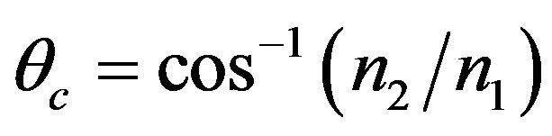
The guidance of the core rays in a straigth step-index optical fiber is achieved by ensuring that the propagation angle q, satisfies the condition: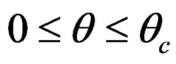 , where the critical angle, qc, and the critical angle, ac, are given respectively, at room-temperature (T0 = 20˚C) by:
 and
and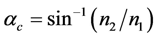 . The numerical aperture (NA) is given at T0 by:
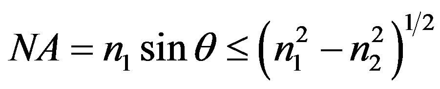 . n1 and n2 are the core and the cladding refractive index respectively [1].
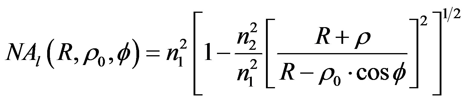
When the optical fiber is bent with a curvature radius R (figure 1), the local numerical aperture at a given location of the optical fiber curved part will be changed. In a meridional-plane of the optical fiber, when the position angle at the beginning of the bend is  = 0˚ or 180˚, the optical fiber behavior becomes identical to the one an optical planar waveguide [1], and the local numerical aperture
  is given, at T0, by:
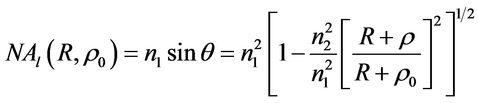 (1)
(1)
where r is the fiber core radius and  is the abscissa on the input optical fiber aperture where the origin is “O”. “r0” will satisfy the relation:
 . However, in all others optical fiber planes, when
  and 180˚, the local numerical aperture,
  , can be calculated by using Equation (1), where the quantity
  replaces
 and “
and “ ” to satisfy the relation:
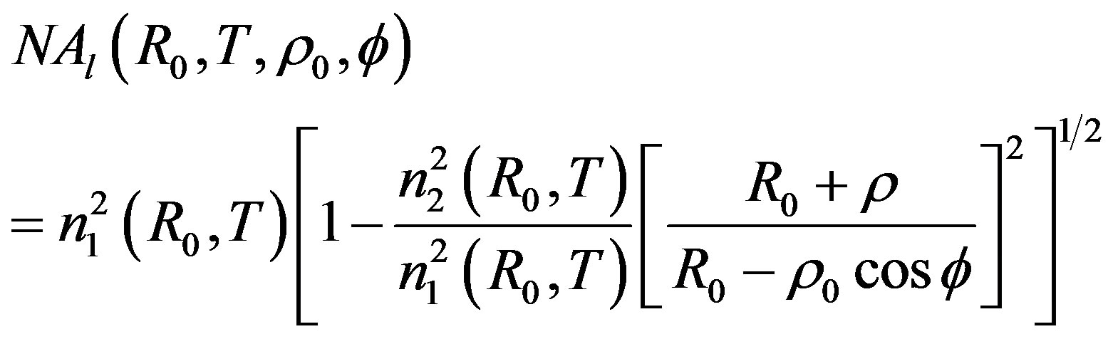
 . Finally, the local numerical aperture of a curved step-index optical fiber is given by:
 (2)
(2)
where is required to satisfy the relation:
 .
.
Equation (2) becomes identical to equation: 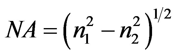 when R is infinite (straight optical fiber case) and becomes identical to equation (1) when f = 0˚ or 180˚ (bent step-index optical planar waveguide case). We used the silica/silicone step-index optical fiber with the following characteristics at T0, for a wavelength l = 633 nm: n1 = 1.4570, n2 = 1401, 2r = 200 µm and NA = 0.4000.
In Figure 2, we plot the local numerical aperture, at T0 for various values of R, as a function of the position “r0” with a value of f. It is clearly seen that the local numerical aperture increase with the increase of the values of R
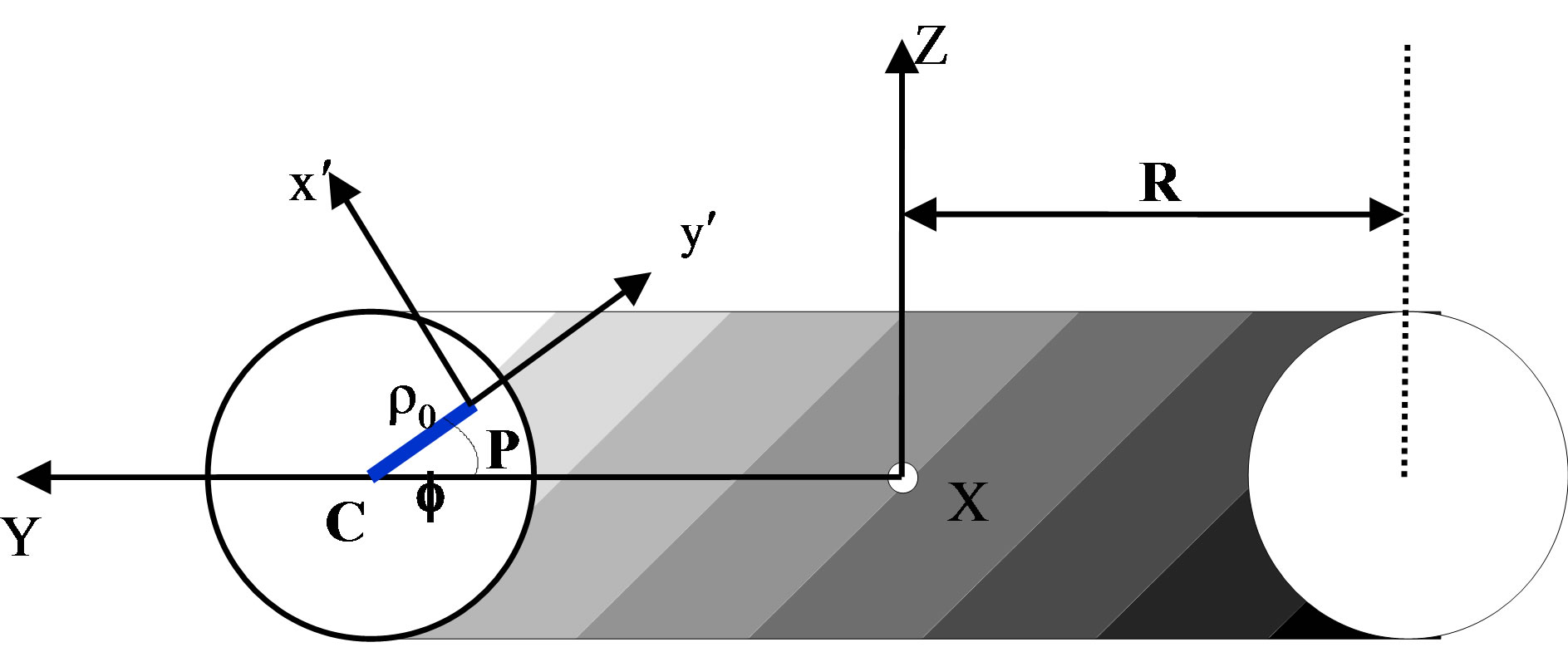
Figure 1. Schematic presentation of a section of a fiber bent with an arc of radius R.
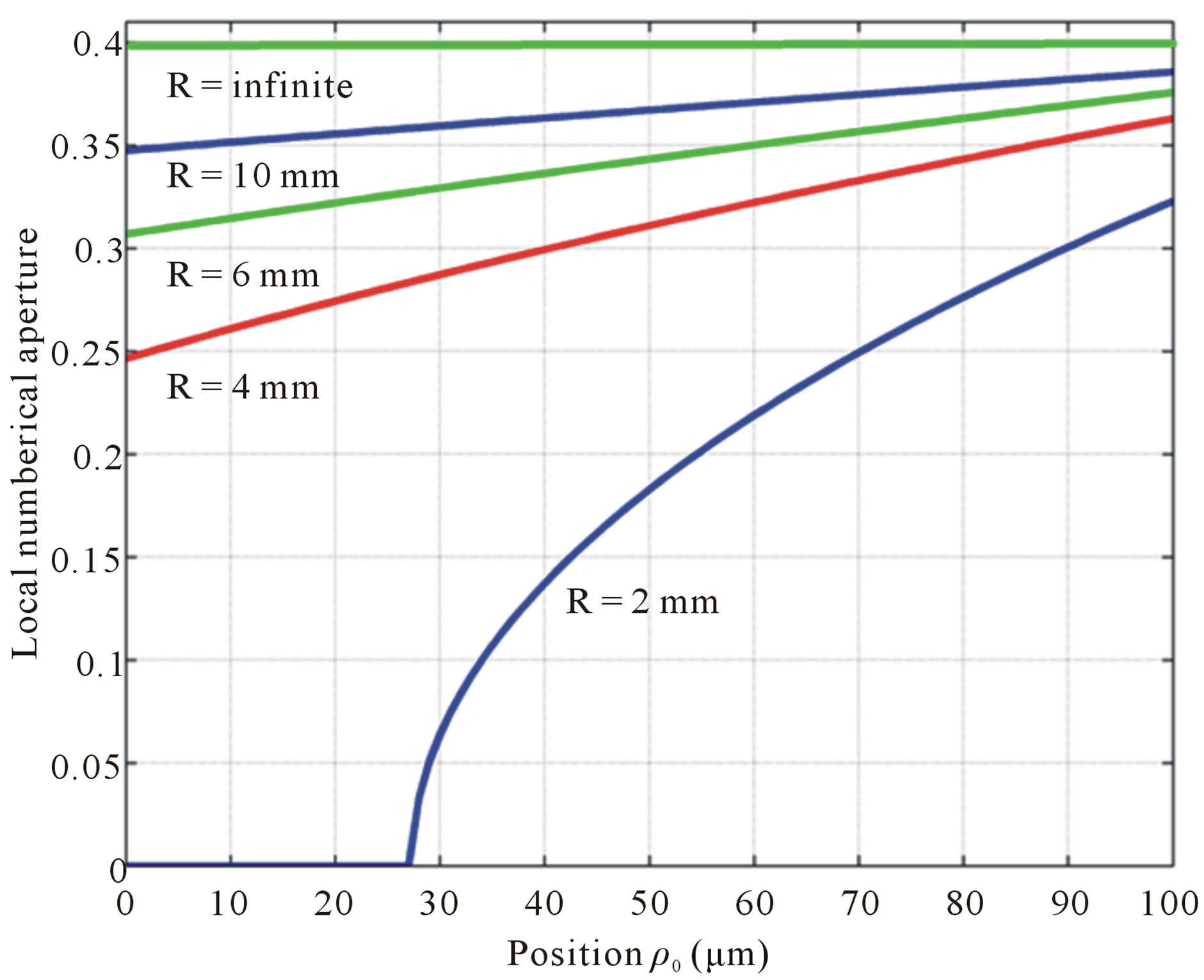
Figure 2. Local numerical aperture according to the position “r0” for several values of R with f = 135˚.
and r0. The maximum of the local numerical aperture is obtained when the angle f is equal to 180˚.
3. An Approach of the Description of the Light Propagation in a Bent Optical Fiber
The ray paths in the core of a step index fiber are straight lines, but the geometrical description is more complicated than in a planar waveguide, that we analyzed previously [1], due to the presence of the skew rays and of the depending on when the optical fiber is curved. In the bent planar waveguide [1], the angle of incidence of a ray on the outer core-cladding interface remains the same along a given ray path, and this property is true for all the ray paths. However, in the bent optical fiber, only the rays entering the bent part of the fiber in the meridionalplane containing this bent part behave in this manner. For the skew rays entering this plane, the subsequent reflections within the core do not follow a simple repeatable pattern because of the asymmetry introduced by bending the fiber. The complicated form of the ray invariants [3] and the differential equations describing the ray path offer no possibility of a simplification. We therefore propose a numerical technique for tracing each ray separately along the bent fiber.
In the Figure 3, we consider an arbitrary incident ray entering the bent section of the optical fiber from the cross section X'X at point “P” at the beginning of the bent part (x = 0). The bent part of optical fiber forms a torus portion by the revolution of the circular cross section about the origin “O” with a radius R. The axis system OXYZ has an axis OX pointing directly into the paper. A local coordinate system ox'y'z' with oz' pointing into the paper is also indicated at P. An arbitrary ray, incident at “P”, has its direction cosines
( ) relative to ox'y'z'. The
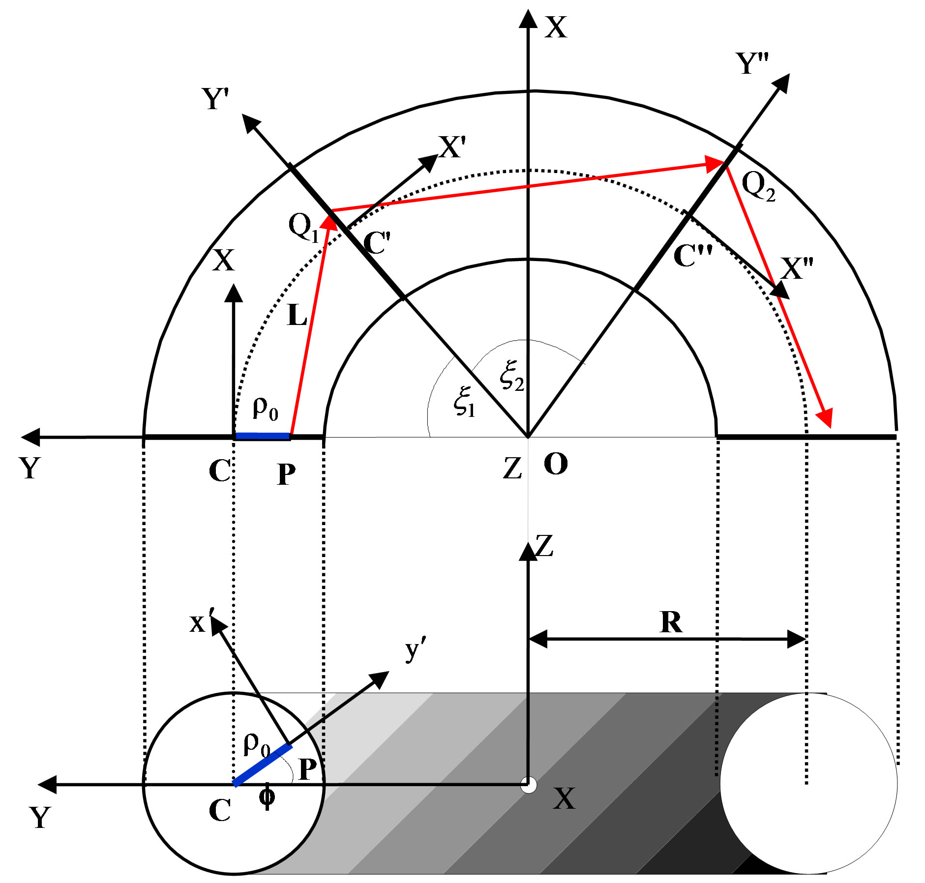
Figure 3. Schematic presentation of a section of a fiber bent with the curvature following an arc having a radius R.
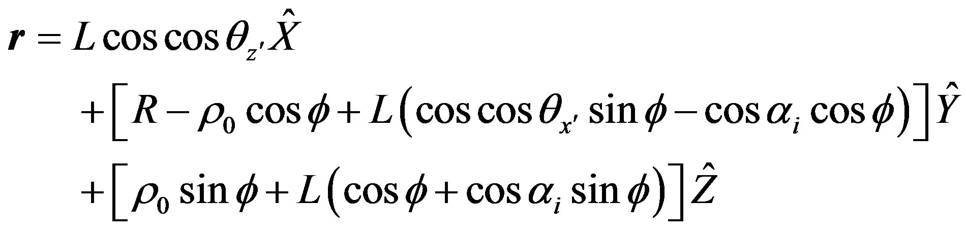
vector OP is given by:
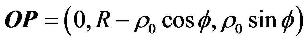 (3)
(3)
where the distance of the point “P” from the fiber center is r0, if we let r be a point along the ray distant “L” from “P” then:
 (4)
(4)
If the ray meets the torus at “ ” then we can write
 , where “
 ” is the position of the first reflection. At “
 ”, we have:
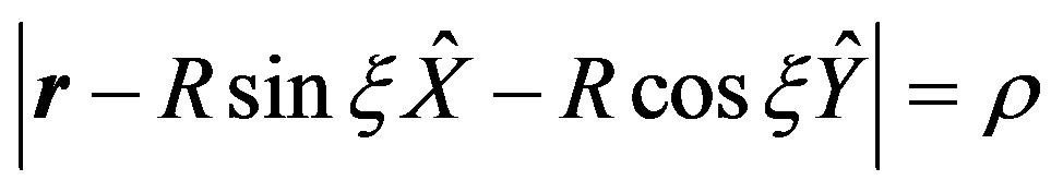 (5)
(5)
And this gives the angular distance x around the axis of the bent optical fiber curvature:
 (6)
(6)
x1 corresponds to  angle. From Equation (6), we deduce an equation which will provide, as a function of the position “L”, the intersection of the optical ray with the bent optical fiber core-cladding interface. The smallest real positive solution of the equation represents the distance “L1”.
From the point of the first reflection “ ” on the optical fiber torus, the optical ray is reflected to another point on the surface of the torus (core-cladding interface) around the bend.
After the first reflection all solutions for the distance “L” to the next reflection are given as solutions of the cubic problem. For obtaining the cubic equation, we must replace r0 by r in the quadratic equation.
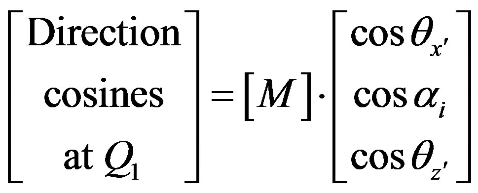
Some simple coordinates rotations and translations simplify the calculation of the incident and the reflected ray angles at each reflection point [2]. The reflected ray direction cosines at “ ” are given by multiplying a matrix transformation “M” by the direction cosines a “P” where:
 (7)
(7)
With: (see Equation (8)).
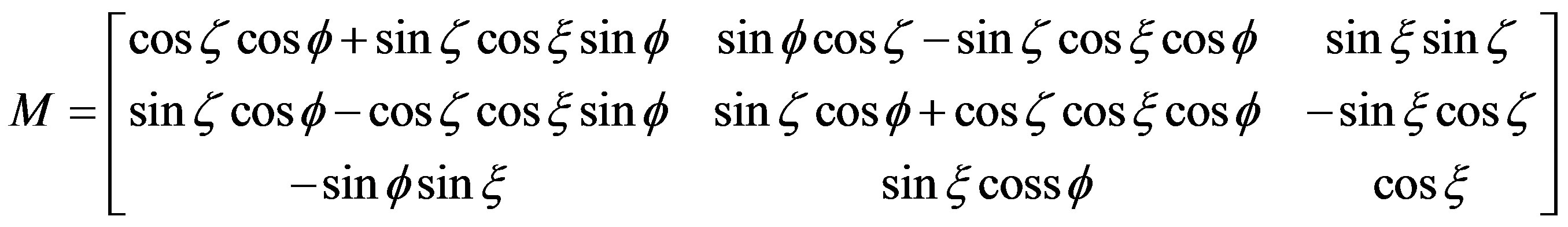 (8)
(8)
A rotation around “ ” will bring the local x-axis tangential to the surface of the torus at
 . This rotation is z. All the others parameters were defined previously.
Having determined the geometry of the ray path, we can then calculate the fractional power loss at each reflection point along a given path by using the following equation:
 (9)
(9)
where g is the attenuation coefficient of each ray, which varies from one reflection to the next one along the bent optical fiber, it is given by:
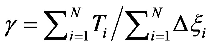 (10)
(10)
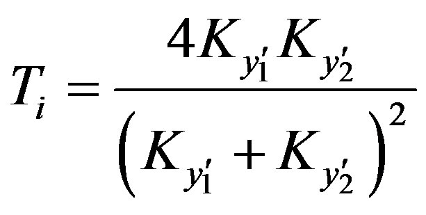
where  is the angular separation between two successive reflections and N is the total number of reflections. We can then use the Generalized Fresnel’s Law to calculate the transmission coefficient
  at each reflection point along a given path.
An algebraic expression for the transmission coefficient of the refracted rays ( ), is given by [3,11,12]:
 (11)
(11)
where  and
and  are given by:
  and
and
 and:
and: .
.
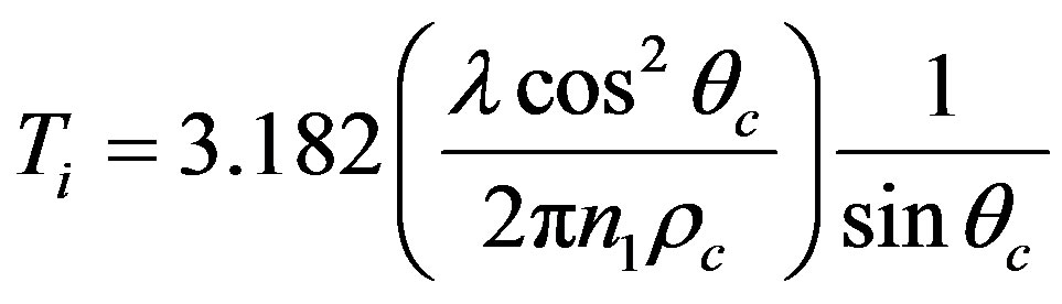
For tunneling rays when , the transmission coefficient at a reflection point of the radius
 is given by:
 (12)
(12)
where the parameter “V” is given by:
 (13)
(13)
The parameter  is the radius of curvature of the core-cladding interface in the incidence plane at “0”. It is defined by the normal to the interface and the incident ray direction. It is given by [3,11,12]:
 (14)
(14)
where  and
and .
.
When , the transmission coefficient is givenby:
 (15)
(15)
But there are some optical rays that reach the interface with incidence angles close to .
.
Finally, the total intensity at the end of the angular length “ ” of the bent part of the optical waveguide is found by a quadruple summation of Equation (9) across the cross-sectional area (r,f) of the optical fiber at X'X and the distribution of the ray angle (q,y) [3,11,12]:
 (16)
(16)
We plot in Figure 4 the normalized power attenuation against the normalized distance (z/r) along the bent fiber axis for a step index optical fiber. Where “z” is the curvature length (z = R·x). Each curve shows the same characteristics. Initially, there is the transition region, having a rapid power loss. This region dominated by the refracted rays and tunnel rays with the largest attenuation coefficient. The behavior of the bent part of the fiber is similar to the planar waveguide bent part [1], but the loss of power in the transition region is not as important, since only a few rays close the meridional plane have large losses.
In Figure 5, we plot the normalized power attenuation against normalized distance (z/r) along the bent planar waveguide and along the bent optical fiber for the same curvature radius (R = 2 mm). Beyond the transient region, the loss of power for a bent optical fiber case is higher than for the bent planar waveguide. This is because the
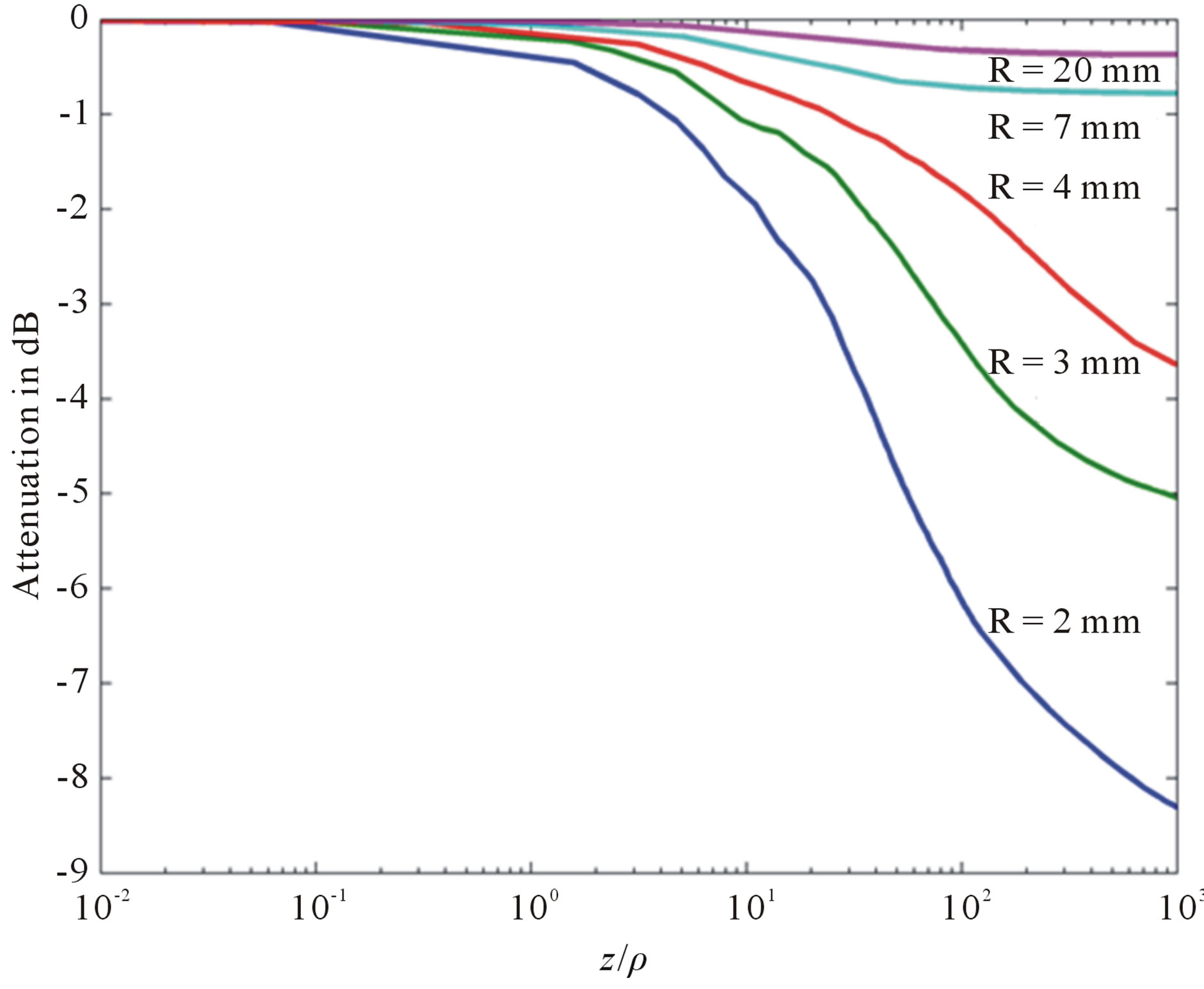
Figure 4. Intensity attenuation according to the ratio (z/r) in the step profile optical fiber for several values of R.
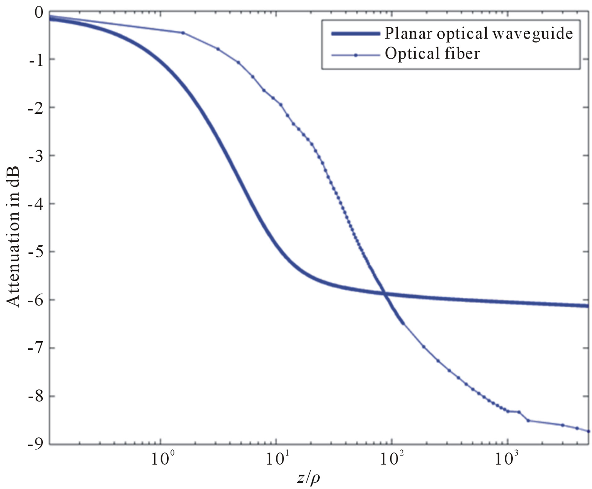
Figure 5. Intensity attenuation comparison between a bent planar waveguide and the bent optical fiber for the same curvature radius (R = 2 mm).
skews rays can pass through the regions of high attenuation, although they may initially have a low attenuation.
4. Temperatures Measurements Principle by Using a Bent Optical Fiber as a Transducer
The optical fiber sensor that we propose is an intrinsic optical fiber sensor; the sensitive element is the curved part of the fiber (Figure 6). This sensor principle is based on the variations of the sensing fiber output light intensity according to the fiber temperature variations. The light energy losses induced by the bending effect of the fiber will be compensated dynamically by the thermal effect; consequently, the output signal intensity is modulated only by the temperature variations.

Figure 6. Temperature sensor general diagram.
5. The Temperature Effect on a Local Numerical Aperture inside a Bent Optical Fiber
For a given radius (R = R0) of the optical fiber curvature and from equation (2), the local numerical aperture inside this bent portion of the fiber according to the temperature is written in the following way:
 (17)
(17)
where the core refractive index and the cladding refractive index are written according to the temperature (T) in the following way [1].
 (18)
(18)
The coefficient 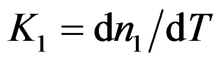 and
and  are respectively the thermo-optic coefficient of core the refractive index and the thermo-optic coefficient of cladding the refractive index. K1 = –3.78 × 10⁻⁴/˚C and K2 = 1.7744 × 10⁻⁵/˚C.
Silicone-based polymers possess a unique set of properties that makes them highly suitable for optical applications. The excellent thermal stability (−115˚C to 260˚C) allows this material to be useful for high temperature sensing applications [22-26].
In this optical fiber the small positive thermo-optic coefficient effect in inorganic glass waveguides used as the core is canceled out by using the negative thermooptic coefficient of polymers used to constitute the cladding.
For an applied temperature T, we plot in figure 7 the local numerical apertures in an optical fiber according to the value of “ ”. We observe that the local numerical aperture increases when the applied temperature increases. Consequently, an optical ray unguided at room temperature becomes guided at temperature greater than T0.
6. Bent Optical Fiber Temperature Response as a Sensor
In this section, we analyze the effect of the temperature variations on the light propagation in a curved optical fiber. We present the effects of the curvature radius on the optical fiber temperature response. For this analysis, the curvature radius R and the length of the bent part of the optical fiber (x) are given. The refractive index of the core and the cladding of the optical fiber depend on the temperature. The geometrical model is used to evaluate the light output power according to the temperature. The output power at the end of the transducer bent part of the fiber is given by:
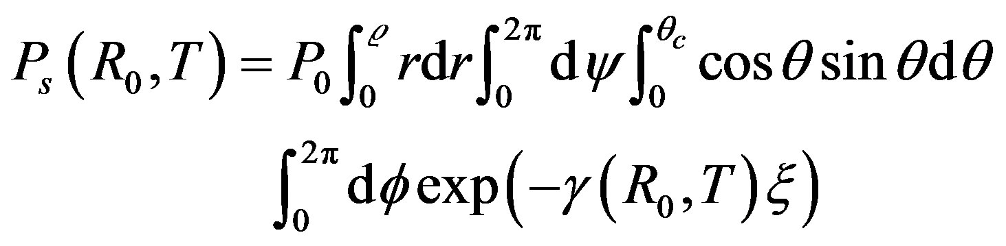 (19)
(19)
For a given curvature length (x = 2pR0), we plot in Figure 8 the normalized output light intensity response of the sensor to the temperature variations for several values of R0.
The response curve of the optical fiber operating as a
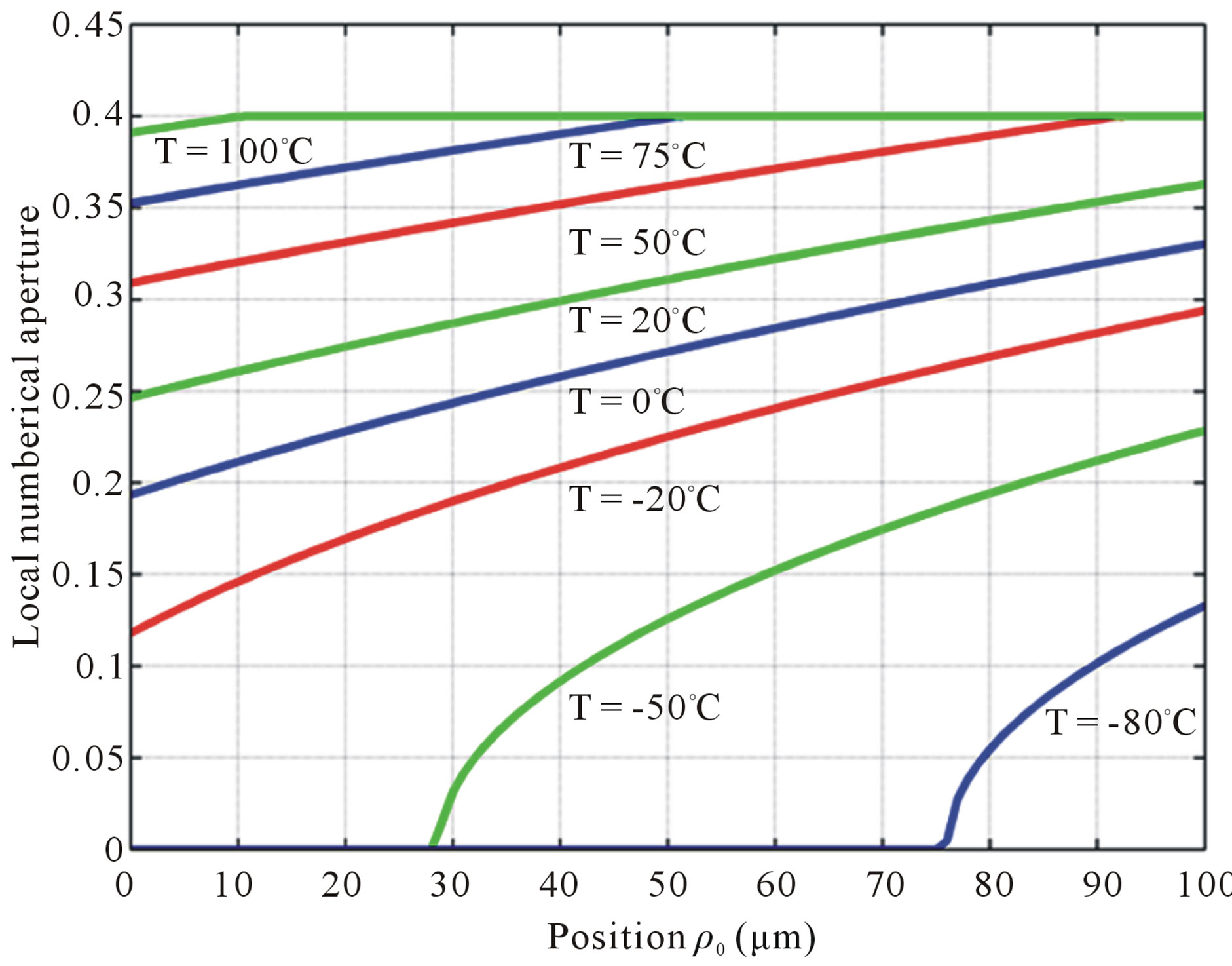
Figure 7. Local numerical aperture according to the position “r0” for several applied temperature, with R0 = 4 mm and f = 135˚.
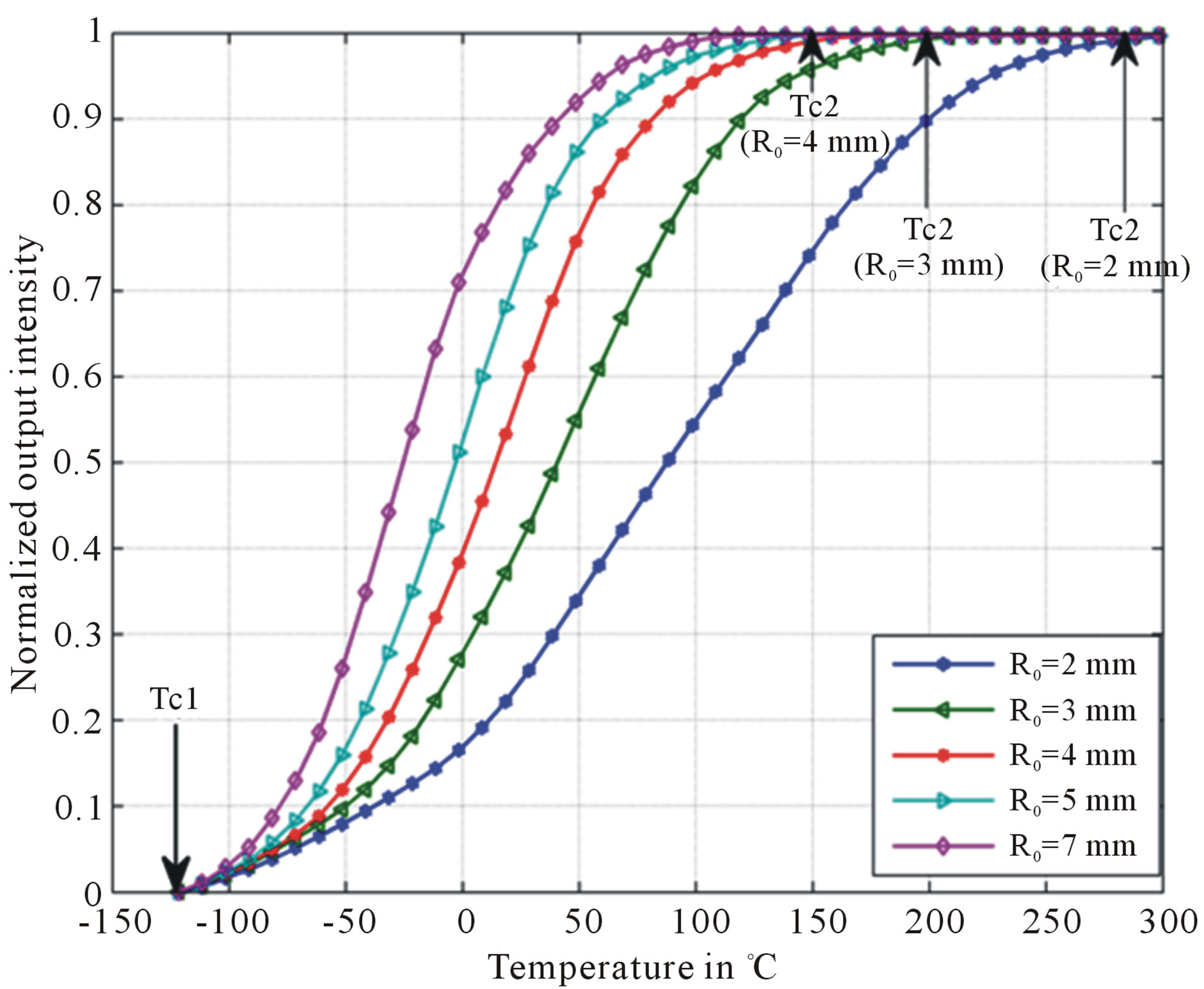
Figure 8. Transmission rate according to the temperature for various curvature radiuses.
temperature sensor that we propose in Figure 8 is similar to the one of a planar waveguide temperature sensor [1]. For this first approach we have not considered errors measuring protocols. We note that the transmission rate (P/P0) increases when the local numerical aperture is increasing up to a saturation level. Each curve is corresponding to the recovery of the losses induced by the refracted optical rays and the recovery of the losses induced by the tunnel effect, up to saturation. We can say that the temperature sensing range of the temperature optical fiber that we propose depends on the curvature radius of the optical fiber.
We deduce from Figure 8 the following statements:
• The part of the response curve between Tc1 and T0 is corresponding to intensity losses caused only by the temperature effect.
• The part of the response curve between T0 and Tc2 is corresponding to intensity losses caused only by the optical fiber curvature.
• The linear region of the optical fiber temperature sensor response is increasing when the curvature radius of the bent fiber is decreasing.
The sensor sensitivity is given by:
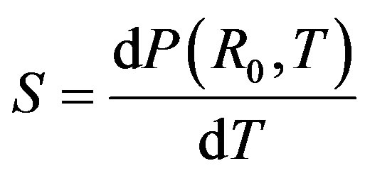 (20)
(20)
where P(R0,T) is the output intensity. We deduce from Figure 8 that the sensitivity of the temperature sensor is inversely proportional to the curvature radius.
Figure 9 shows the temperature response curve fitting for R0 = 2 mm. In the liner zone between 20˚C and 180˚C, this sensor has a sensitivity of 0.004˚C−1.
7. Conclusion
The response to temperature variations on the bending
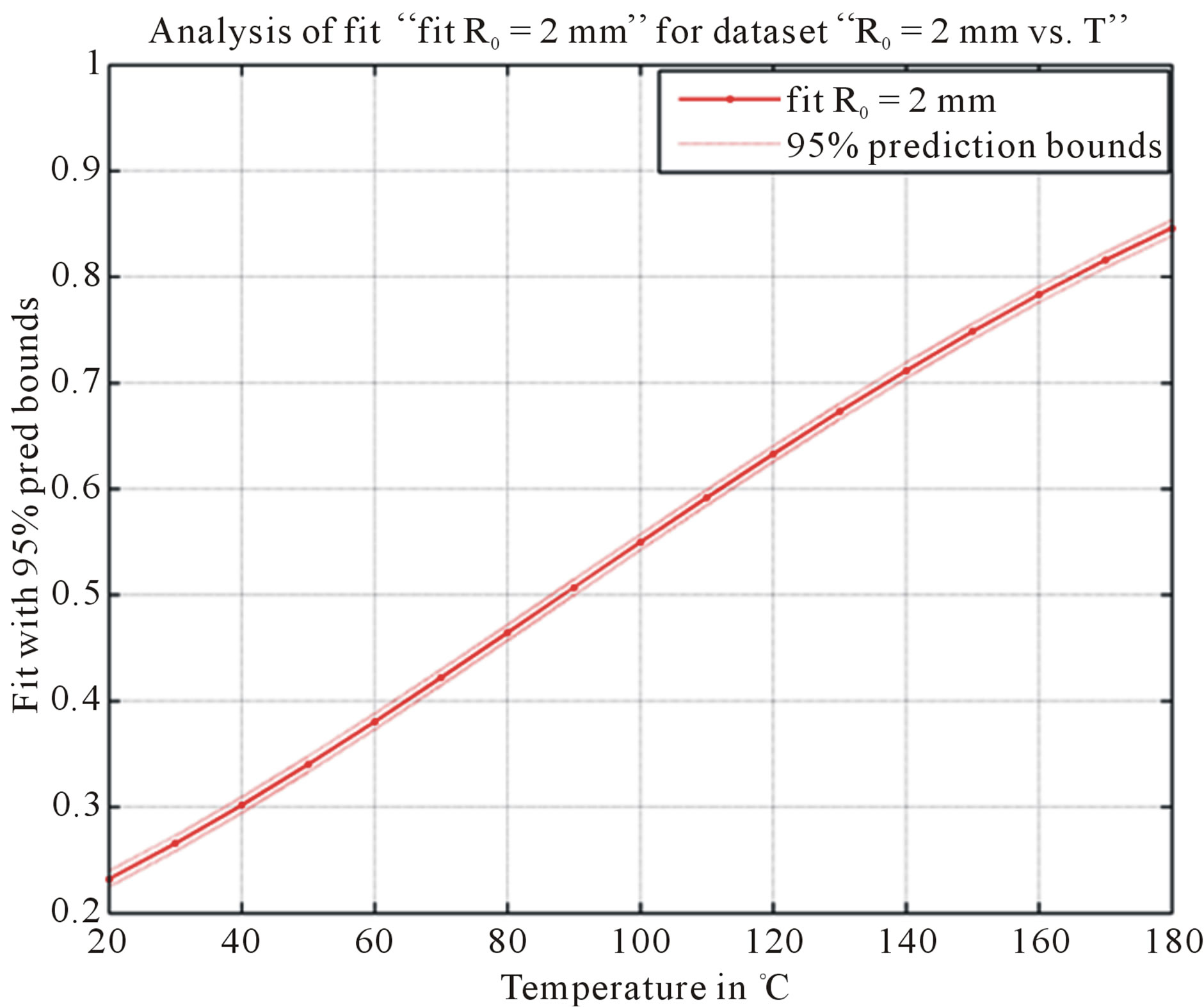
Figure 9. The temperature response curve fitting for R0 = 2 mm between 20˚C and 180˚C.
light power loss of a multimode optical fiber with different bent fiber curvature radii have been analyzed. It has been found that the bending losses due to the internal optical fiber numerical aperture variations increase when the fiber bending angle increase. The more important losses are caused by refraction and tunnel effects. We have shown that a bent optical fiber can be used as a temperature transducer. The use of an optical fiber curved during its manufacturing at high temperature allows to minimize some residual mechanical effects, and allows to use rigorously the geometrical approach to describe the light propagation, to evaluate the losses in light power output values and to calibrate the temperature sensor. We have shown that if we use, for example a silica/ silicone fiber as a transducer, we can obtain good performances with an excellent sensitivity and an excellent linearity associated to a large temperature measurement range, mainly because the thermo-optic effect value on the silicone is negative and important.
REFERENCES
- M. Remouche, R. Mokdad and A. Chakari, “Intrinsic Integrated Optical Temperature Sensor Based on Waveguide Bend Loss,” Optics & Laser Technology, Vol. 39, No. 7, 2007, pp. 1454-1460. doi:10.1016/j.optlastec.2006.09.015
- M. Remouche, R. Mokdad and M. Lahrashe, “Intrinsic Optical Fiber Temperature Sensor Operating by Modulation of the Local Numerical Aperture,” Optical Engineering, Vol. 46, No. 2, 2007, p. 024401. doi:10.1117/1.2709854
- A. W. Snyder and J. D. Love, “Optical Waveguide Theory,” Chapman & Hall, Upper Saddle River, 1983.
- A. Zendehnam, M. Mirzaei1 and A. Farashiani, “Investigation of Bending Loss in a Single-Mode Optical Fibre,” Pramana Journal of Physics-Indian Academy of Sciences, Vol. 74, No. 4, 2010, pp. 591-603.
- R. Ulrich, S. C. Rashleigh and W. Eickhoff, “BendingInduced Birefringence in Single-Mode Fibers,” Optics Letters, Vol. 5, No. 6, 1980, pp. 273-275. doi:10.1364/OL.5.000273
- E. A. J. Marcatilli, “Bends in Optical Dielectric Guides,” Bell System Technical Journal, Vol. 48, No. 7, 1969, pp. 2103-2132.
- D. Gloge, “Bending Loss in Multimodes Fibers with Graded and Upgraded Core Index,” Applied Optics, Vol. 11, No. 11, 1972, pp. 2187-2506. doi:10.1364/AO.11.002506
- D. Marcuse, “Influence of Curvature on the Losses of Doubly Clad Fibers,” Applied Optics, Vol. 21, No. 23, 1982, pp. 4208-4213. doi:10.1364/AO.21.004208
- M. Semenkoff, “Bending Effect on Light Propagation in an Optical Fiber: Application to a Temperature Sensor,” Optics and Lasers in Engineering, Vol. 17, No. 3-5, 1992, pp. 179-186. doi:10.1016/0143-8166(92)90035-6
- D. Marcuse, “Bending Losses of the Asymmetric Slab Waveguide,” Bell System Technical Journal, Vol. 50, No. 8, 1969, pp. 2551-2563.
- A. W. Snyder and D. J. Mitchell, “Generalized Fresnel’s Laws for Determining Radiation Loss from Optical Waveguides and Curved Dielectric Structures,” Optik, Vol. 40, No. 4, 1974, pp. 438-459.
- A. W. Snyder and D. J. Mitchell, “Bending Losses of Multimode Optical Fibers,” Electron Letter, Vol. 10, No. 1, 1974, pp. 11-13. doi:10.1049/el:19740008
- J. Dakin, “Optical Fiber Sensors,” Artech House, Norwood, 1988.
- T. S. Yu Francis, “Fiber Optical Sensors,” Marcel Dekker, Inc., New York, 2002.
- F. Pang; W. Liang and W. Xiang, “Temperature-Insensitivity Bending Sensor Based on Cladding-Mode Resonance of Special Optical Fiber,” IEEE Photonics Technology Letters, Vol. 21, No. 2, 2009, pp. 76-78. doi:10.1109/LPT.2008.2008657
- R. P. Hu and X. G. Huang, “A Simple Fiber-Optic Flowmeter Based on Bending Loss,” IEEE Sensors Journal, Vol. 9, No. 12, 2009, pp. 1952-1955. doi:10.1109/JSEN.2009.2031845
- R. M. Gavalis, P. Y. Wong and J. A. Eisenstein, “Localized Active-Cladding Optical Fiber Bend Sensor,” Optical Engineering, Vol. 49, No. 6, 2010, p. 064401. doi:10.1117/1.3449110
- X. Chen, C. Zhang and D. J. Webb, “Bragg Grating in a Polymer Optical Fibre for Strain, Bend and Temperature Sensing,” Measurement Science and Technology, Vol. 21, No. 9, 2010, p. 094005.
- J. H. Kuang, P. C. Chen and Y. C. Chen, “Plastic Optical Fiber Displacement Sensor Based on Dual Cycling Bending,” Sensors, Vol. 10, 2010, pp. 10198-10210. doi:10.3390/s101110198
- J. Zhang, H. Liu and X. Wu, “Curvature Optical Fiber Sensor by Using Bend Enhanced Method,” Frontiers of Optoelectronics in China, Vol. 2, No. 2, 2009, pp. 204- 209. doi:10.1007/s12200-009-0032-x
- N. singgh, V. Mishra and S. C. Jain, “Enhanced Sensitivity Refractive Index Sensor Based on Segmented Fiber with Bending,” Indian Journal of Pure & Applied Physics, Vol. 47, No. 9, 2009, pp. 655-657.
- Z. Zhang, G. Z. Xiao and P. Zhao, “Planar Wave GuideBased Silica-Polymer Hybrid Variable Optical Attenuator and Its Associated Polymers,” Applied Optics, Vol. 44, No. 20, 2005, pp. 2402-2408. doi:10.1364/AO.44.002402
- H. Ma, A. K.-Y. Jen and L. R. Dalton, “Polymer-Based Optical Waveguides: Material, Processing, and Devices,” Adv Mater, Vol. 14, No. 19, 2002, pp. 1339-1365.
- M. Zhou, “Low-Loss Polymeric Material for Waveguide Components in Fiber Optical Telecommunication,” Optical Engineering, Vol. 41, No. 7, 2002, pp. 1631-1643. doi:10.1117/1.1481895
- L. Eldada, “Advance in Polymer Integrated Optics,” IEEE Journal of Selected Topics in Quantum Electronics, Vol. 6, No. 1, 2000, pp. 54-68.
- T. Watanabe, N. Ooba and S. Hayashida, “Polymeric Optical Waveguide Circuits Formed Using Silicone Resin,” Journal of Lightwave Technology, Vol. 16, No. 6, 1998, pp. 1049-1055. doi:10.1109/50.681462