Journal of Surface Engineered Materials and Advanced Technology
Vol.4 No.1(2014), Article ID:42044,8 pages DOI:10.4236/jsemat.2014.41001
Solid Particle Erosion Behaviour of TiN Coating on AISI 4140 Steel
J. R. Laguna-Camacho1, J. E. Escalante-Martínez1, R. Cruz-Vicencio1, J. V. Méndez-Méndez2, I. Arzate-Vázquez2, I. Hernández-Romero3, M. Vite-Torres4
1Faculty of Electric and Mechanical Engineering, Universidad Veracruzana, Poza Rica de Hidalgo, Veracruz, México; 2Centro de Nanociencias y Micro y Nanotecnologías, IPN, Mexico City, México; 3Faculty of Chemical Engineering, Universidad Veracruzana, Poza Rica de Hidalgo, Veracruz, México; 4Instituto Politécnico Nacional, SEPI, ESIME, Unidad Profesional “Adolfo López Mateos” Tribology Group, Mechanical Engineering Department, Mexico City, México.
Email: juanrlaguna@hotmail.com
Copyright © 2014 J. R. Laguna-Camacho et al. This is an open access article distributed under the Creative Commons Attribution License, which permits unrestricted use, distribution, and reproduction in any medium, provided the original work is properly cited. In accordance of the Creative Commons Attribution License all Copyrights © 2014 are reserved for SCIRP and the owner of the intellectual property J. R. Laguna-Camacho et al. All Copyright © 2014 are guarded by law and by SCIRP as a guardian.
Received October 23rd, 2013; revised December 20th, 2013; accepted January 10th, 2014
ABSTRACT
In this study, the performance against erosive wear of PVD TiN (titanium nitride) coating was evaluated using an erosion test rig similar to that described in the standard ASTM G76-95. This coating normally has various industrial applications such as tapping, drilling, dry machining and punching. Angular silicon carbide (SiC) was used as an abrasive particle with a grain size of 350 - 450 µm. Erosion tests were carried out using different incident angles, 30˚, 45˚, 60˚ and 90˚ with a particle velocity of 24 ± 2 m/s, an abrasive flow rate of 0.7 ± 0.5 g/min, and the test temperature was between 35˚C and 40˚C. The particle velocity and the abrasive flow rate were low in all of the tests to reduce the interaction between the incident and the rebounding particles in the system. The surfaces were examined with a scanning electron microscope (SEM) to characterize the erosive damage. The wear mechanisms identified were brittle fracture characterized by radial cracks on the surface by multiple impact and a few pits at 30˚, while a few cracks and the formation of craters in random positions were observed at angles near or at 90˚. Elliptical scars were observed at 30˚ and 45˚, which are a characteristic feature when the specimens are impacted at low-incident angles (α ≤ 45˚) whereas a roughly circular scar was seen at 60˚ and 90˚. In addition, roughness variations were analyzed using atomic force microscopy (AFM), before and after the erosion tests, and the results exhibited an increase in the roughness as the TiN samples were impacted at angles near or at 90˚.
Keywords: Erosion Wear; PVD Nitride Coating, TiN; Wear Mechanisms
1. Introduction
Solid Particle Erosion (SPE) is the progressive loss of material that results from the repeated impact of small, solid particles or liquid on a surface [1]. Depending on the kind of equipment, erosion phenomena may appear in various forms. Though harmful as a rule, erosion sometimes can be used as a method of processing but it is a serious problem in many engineering systems, including streams, jet turbines, pipelines and valves carrying particulate matter and water turbines.
Surface coating is an effective method to improve the durability of the materials used in different environments. New coating deposition techniques developed over the last two decades offer a wide variety of possibilities to tailor surfaces with many different materials and structures. In particular, physical vapour deposition (PVD) techniques have made it possible to deposit thin coatings a few micrometers thick in a temperature ranging from high temperature down to room temperature. Nitride based hard compound coatings prepared by various physical vapour deposition processes are finding increasing applications for nearly every demand. High hardness, excellent wear and corrosion resistance enable them to significantly improve tool life.
In relation to research on solid particle erosion on PVD nitride coatings, several researchers have conducted experimental works. For instance, Deng Jianxin, et al. [2] conducted a study on erosion wear of different PVD nitride coatings such as CrN, TiN, CrAlN and TiAlN. These were deposited on YT15 cemented carbide by cathode arc-evaporation technique. Silicon carbide powder with a grain size between 40 - 100 µm was used as abrasive particle. Erosion tests showed that among all the coatings tested, the TiAlN coating exhibited the smallest wear depth under the same test conditions; while the CrN coating showed the highest wear depth. The time of the coating penetration for CrN sample was about 40, since the wear depth reached 1.8 µm after 40 s erosion operation (the coating thickness of CrN was 1.8 µm), while for the TiAlN coating, the wear depth reached only 1.5 µm after 380 s erosion operation, which was far less than its coating thickness (2.64 µm). Therefore, the TiAlN coating was proved to have the highest erosion resistance over the other coatings. On the other hand, analysis of the eroded surfaces demonstrated that TiN and CrN coatings showed a typical brittle fracture induced removal process which experienced erosive wear damage involving delamination and brittle fracture, while TiAlN and CrAlN experienced significantly less erosion damage than CrN and TiN coatings, and exhibited microcutting and cycle fatigue fracture of material removal mode.
B. Jonsson, et al. [3] conducted a research evaluating a TiN layer coating on high speed steel with 1 µm thickness deposited by reactive magnetron sputtering technique using various erosion parameters. The impact angle was 90˚ and angular quartz particles were used as the abrasive particles. Wear mechanisms such as different size craters, brittle fracture and pitting action, were normally observed on the surface. A theoretical model was developed to describe the erosion process in terms of particle dose and two characteristic film parameters. There were the mean area affected by a single impact and the mean number of consecutive impacts in one site necessary to make the coating spall. It was an attempt to correlate the time-coating loss with the practical levels of adhesion as revealed by single-pass scratch test. It was concluded that erosion testing could be a more sensitive means to asses “practical adhesion” than scratch testing.
P. J. Burnett and D. S. Rickerby [4] carried out a research related to the erosion behavior of thick and thin PVD titanium nitride coatings on two different steel substrates (20-carbon steel and 18-9-1 stainless steel) subjected to sharp and blunt erodent particles. Some of the parameters used in this experimentation were particle velocities between 14 and 35 m/s (determined using the double disc method), a mass flow rate of 1 g/sec and two impact angles (45˚ and 90˚). The erodent particles were glass beads (blunt shape) and alumina (grit shape).
In this particular work, the possibility to use solid particle erosion tests to assess the coating adherence as in the standard and well accepted scratch testing was mentioned. A correlation about the morphology of the coating loss between the scratch tests with erosion behavior was highlighted; for instance, as the abrasive particle for the tests was angular alumina, the predominant coating failure mechanism for the coated 20-carbon steel substrate was elastic/plastic chipping in both the scratch and erosion tests. In contrast, the TiN coating on the stainless steel substrate showed a tendency to spall under both erosion and scratch testing. It was also interesting to note that mass of erodent for coating loss under erosion increased with coating thickness, and this was correlated with an increase in the critical load (LC), due to a higher thickness of the coating in the scratch tests.
Telling & Field [5] carried out a study of the degradation of three nominally brittle materials (diamond, sapphire and zinc sulphide) when impacted with small, fastmoving particles of quartz. In this work, it was observed that zinc sulphide showed a central deformation and cone, radial and lateral cracking (top left), where a large area of material was removed. The other two materials although exhibiting similar damage, with partial cones and lateral cracks, were less damaged. In addition, the fragmentation of the quartz particles was examined and it was concluded that the particle takes a long time to fragment after contact with the surface. “Assuming that fracture is not initiated at the point of contact, but at a distance of the order of the particle radius away from the contact, then the load could potentially rise above the particle’s static strength. Therefore, being severe and causing the damage on the surface…” Shipway and Hutchings [6] carried out a study of solid particle erosion on different coatings. In this particular study, a method was described for analyzing the results of erosion tests on coatings. The behavior of the coating was characterized in terms of a single quantity: the dose (mass per unit area) of erodent particles of a particular type and velocity needed to remove the coating. This method had been applied to a diverse range of coatings: paint coatings, anodized films on aluminium, PVD titanium nitride on steel and DLC carbon films on steel.
In this study, an analysis of the erosion behavior of PVD titanium nitride deposited on AISI 4140 steel by magnetron sputtering technique was performed. The aim of the experimentation was to provide information about the behavior of this coating against solid particle erosion subjected to the impact of silicon carbide particles at different incident angles. The impact angle was a parameter that determined the erosion resistance of this coating.
2. Experimental Details
2.1. Sample Preparation
The substrate material was AISI 4140 steel in a soft annealed condition. The steel was heated to temperatures between 830˚C - 850˚C in a furnace and it was slowly let to cool at a temperature no higher than 65˚C per hour. The hardness of the material used was 280 HV. Mechanical applications such as conveyor parts, gears, spindles and pump shafts are common in the soft annealed condition [7]. The specimens were ground flat with 180-grit silicon carbide paper and polished using 0.3 µm alumina particles over a polished-disc shaped cloth. The roughness average value was 3.5 nm (Ra) with a standard deviation of 0.30. The chemical composition is presented in Table1
The coating used for these tests was titanium nitride (TiN) with a thickness of 4 µm. It was deposited using cathodic erosion equipment; Intercovamex V-3, with the DC power source, MCX 500, with a capacity of 500 W (DC Magnetron Sputtering). The substrates mounted on the disc of the vacuum chamber, and the equipment was prepared to reach the required vacuum pressure to make the deposit, which was approximately 1.0 × 10⁻⁵ mbar. In addition, the substrates were biased 50 V negative with respect to earth to induce ion bombardment of the coating during deposition and thereby promote the formation of a dense, fine-grained coating. The separation was 5 cm between Ti target and the substrate (AISI 4140 steel). The deposition of TiN was done in the Ar and N2 partial pressures environment of 9.9 × 10⁻³ mbar and 1.8 × 10⁻³ mbar for 90 minutes. The titanium nitride coating was deposited at a temperature of 400˚C throughout the process. The parameters of TiN deposition are presented in Table2
Figure 1 shows the SEM micrograph of the morphology of the coating before the erosion tests. An EDS

Table 1 . Chemical composition AISI 4140.
Table 2. Equipment conditions.
PAr = Argon gas pressure during deposition, PN2 = Nitrogen gas pressure during deposition, Ts = Substrate temperature during deposition, E = Potential difference, T = Deposition time, P = Power of the DC Magnetron Sputtering. The fusion temperature of the deposited coating was (CrN = 1050˚C).
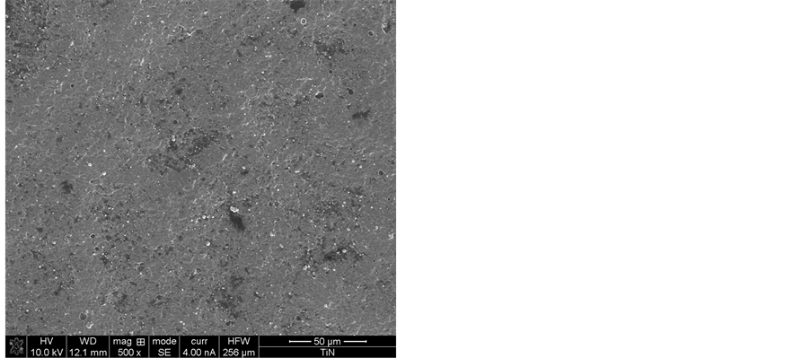
Figure 1. SEM photograph of TiN coating.
Analysis was performed to obtain the chemical composition of the coating (see Table 3 and Figure 2). In addition, roughness values of TiN coating before and after erosion testing were obtained by using an AFM (Microscope diMultimode V, Vecco, Controller diNanoscope V). The surface’s roughness before the tests was 149 nm (Ra) with a standard deviation of 27.3 (five measurements in different zones) and the projected surface area was 5 × 5 µm2. Figure 3 shows a 3D profile of the initial roughness.
On the other hand, hardness tests were carried out and the average value was 1283 HV with a standard deviation of 273.1 (15 measurements). The applied load was 100 mN. These results obtained using a Nanoindentation Tester (TTX-NHT, CSM Instruments). In addition, the Young’s Modulus of the TiN coating was calculated and the average result was 282.7 GPa with a standard deviation of 50.18 (after 15 measurements) Figure 4 shows a Vickers indentation on TiN coating surface.
The samples had a rectangular shape with dimensions of 50 × 25 mm2 and 3 mm in thickness. The abrasive particles used were silicon carbide (SiC) with an angular shape as shown in Figure 5. The chemical composition of silicon carbide is shown in Table4 Silicon carbide was used to accelerate the erosive wear process and to evaluate the performance of this coating under severe erosive conditions. Particle size distribution was obtained using Analysette 28 image sizer. The selected measuring range for SiC particles, was between 26 µm and 2.6 mm. The particle size grain between 350 - 450 µm was the most consistent. Most particles were found in this particular range. The average particle size was 342 µm with a standard deviation of 127 for the first measurement (19285 particles) shown in grey color in the graph in Figure 6. On the other hand, a second measurement (14507 particles) carried out and the average particle size
Table 3 . Chemical composition of TiN coating.
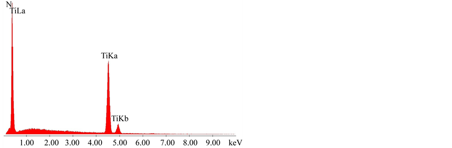
Figure 2. EDS analysis of TiN coating.
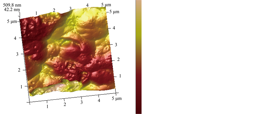
Figure 3. 3D roughness profile of TiN before test.
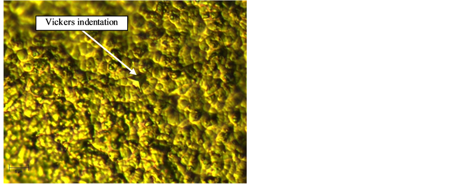
Figure 4. Vickers indentation on TiN coating.
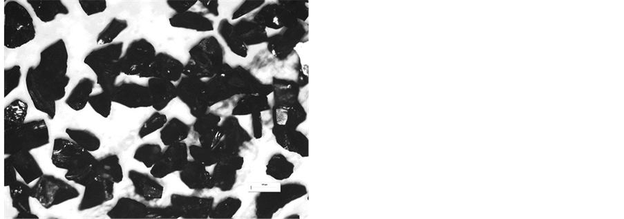
Figure 5. Silicon carbide particles (SiC).
Table 4. Silicon carbide composition.
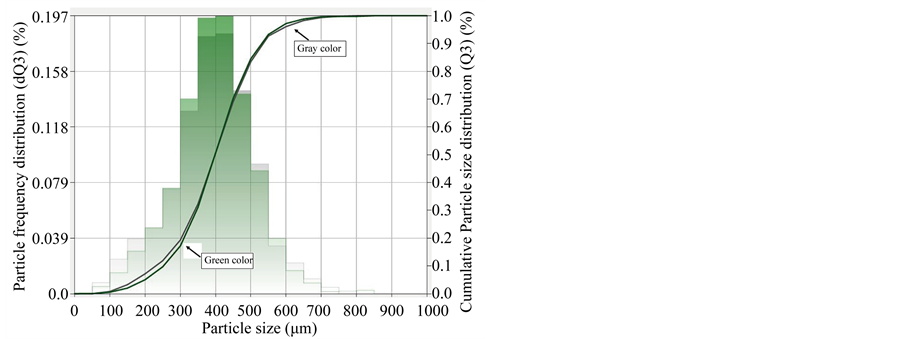
Figure 6. Particle size distribution.
was 353 µm with a standard deviation of 136 (green color). Both measurements were close.
2.2. Test Procedure
Erosion tests were performed by using an apparatus based on that shown in ASTM G76-95 test standard [8]. Figure 7 shows a schematic diagram of the erosion rig [9]. In this device, abrasive particles propelled onto the specimen surfaces through a stainless steel nozzle, are driven by air pressure generated by an air compressor.
Two tests were performed for each impact angle, 30˚, 45˚, 60˚ and 90˚. These angles were selected to evaluate the coating material at low and high incident angles and to determine their behaviour under different testing conditions. The coating was eroded for 240 sec, although it was removed every 60 sec to determine the amount of mass loss. A particle velocity of 24 ± 2 m/s and an abra-

Figure 7. Erosion rig.
sive flow rate of 0.7 ± 0.5 g/min were used to reduce the effects of interaction between incident and rebounding particles. The reduction of this effect was reached at low impact angles such as 30˚ and 45˚, where the abrasive particles impacted the material, slid along the surface and then fell away. However, a higher level of interaction between particles was observed at 90˚. In all of the tests, the specimens were located at 10 mm distance from the end of the stainless steel nozzle. The nozzle had the following dimensions: 4.7 mm internal diameter, 6.3 mm external diameter and a length of 260 mm. The room temperature was between 35 and 40˚ C. The specimens were weighed using an analytical balance (accuracy of ± 0.0001 g) before each test and every 1 min were removed and cleaned with acetone and then weighed to determine the amount of mass loss. Micrographs of the eroded surfaces were obtained using a scanning electron microscope (SEM) Quanta 3D FEG (FEI) to analyse and to identify the possible wear mechanisms.
3. Results and Discussion
3.1. Erosion Damage
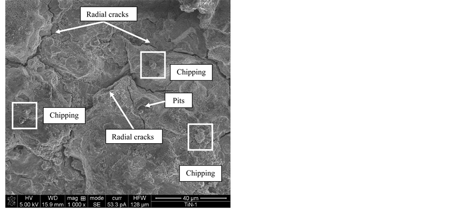
SEM images of the erosion damage on TiN coating are presented in Figures 8(a) and (b). The wear mechanism identified was brittle fracture, characterized by radial cracks on the surface by multiple impacts; and a few pits. The radial cracks [3-5] could have their origin in the formation of median and lateral cracks formed under the coating surface due to the direct impact of the abrasives particles. The sliding component at lower impact angles, was significant due to the higher wear damage caused at this particular incident angle, of course, the hardness of the abrasive particle could lead to a higher fragmentation during the impact, which inflicted that more particles acted on the surface leading to the generation of greater erosion damage on the coating surface. AFM image shows the asperities of the surface damaged at 30˚; the red colour described the deepest zones of the wear scar, while the yellow one exhibits the higher peak regions. The average roughness values for 30˚ and 90˚ were 232 nm with a standard deviation of 60.6 and 319 nm with a standard deviation of 81.5, respectively.
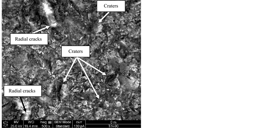
In respect to the wear damage at 90˚, a few cracks were observed on the surface in the upper and bottom part of the SEM micrograph, it was also exhibited pitting action and the formation of craters in random positions as shown in Figure 9 and in previous erosion studies [3-5]. In this particular case, the abrasive particle just displaced the coating. It was assumed because the erosion rate was low at 60˚ and 90˚.
3.2. Erosion Behavior of TiN Coating
Figures 10(a) and (b) presents the results of the mass loss of the tested materials after 4 min at all incident angles (30˚, 45˚, 60˚ and 90˚). In this particular case, the wear damage is proportional to the elapsed time. It has been observed commonly in other erosion studies [10-12]. PVD Titanium nitride (TiN), deposited on AISI 4140 steel, exhibited higher wear damage at 30˚ than at 90˚.
Figure 11 shows a plot of the erosion rate versus the impact angle for all the tested coatings. Here, it is possible to conclude that TiN coating exhibited a ductile type behavior, reaching their maximum erosion rate at 30˚ and 45˚, respectively. The wear damage was considerable reduced as the impact angle increased (see Figure 11).
Figure 12 shows a plot of the erosion rate versus the impact angle for the tested coating. The total erosion rate
 (a)
(a)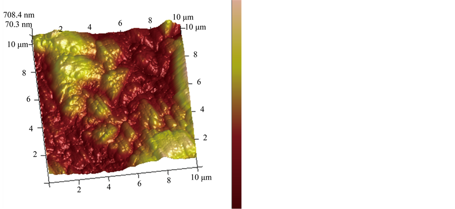 (b)
(b)
Figure 8. (a) Erosion damage on TiN coating at 30˚; (b) 3D roughness profile at 30˚.
was determined dividing the mass loss (g) by the total mass of abrasive particles (g) that stroke the coating surface after 240 sec, for each impact angle. Here, it is possible to conclude that the TiN coating exhibited a ductile type behaviour, reaching its maximum erosion rate at 30˚, reducing considerably as the incident angle reduced up to 90˚. It was assumed that the sliding component of the angular abrasive particle at 30˚, led to cause high cutting action on the coating surface, it because of the high hardness and capacity of the abrasive particles to act on the surface, it inflicted that the wear damage were increased. In addition, the first impact of the abrasive particles on the surface and a possible reimpact led to accelerate the wear rate at this impact angle.
 (a)
(a)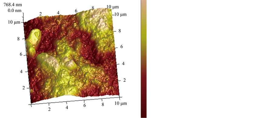 (b)
(b)
Figure 9. (a) Erosion damage on TiN coating at 90˚; (b) 3D roughness profile at 90˚.
4. Conclusions
The results presented in the discussion section allow some conclusions to be drawn in relation to the erosion behavior of PVD titanium nitride coating deposited on AISI 4140 steel.
Titanium nitride coating showed its maximum erosion rate at 30˚. This coating exhibited a ductile type behavior in relation to the graph shown in the erosion literature in Figure 11, where it is possible to observe that ductile materials reach their maximum erosion rate at low impact angles (α ≥ 45˚). Here, the sliding component, the first impact and re-impact of the angular abrasive particles on the coating surface, increased the wear damage at low incident angles. Conversely, the wear rate reduced considerably at angles near or at normal impact, 60˚ and 90˚.
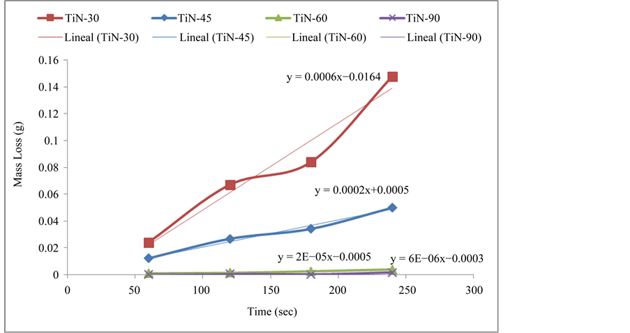
Figure 10. Mass loss vs time graph.
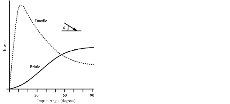
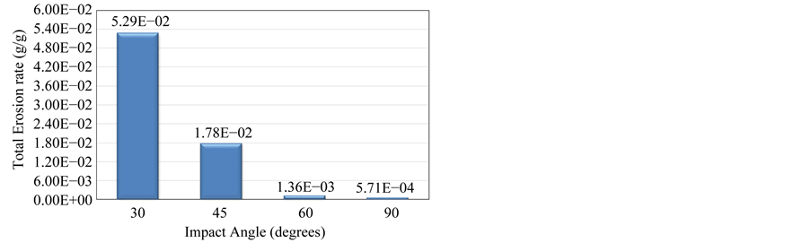
Figure 12. Comparison of the wear rates at different impact angles.
SEM images were used to identify the wear mechanisms characterized by brittle fracture due to high hardness of the coating, radial cracks caused by median/lateral/cone cracks under the coating surface formed. Of course, pits and craters with different sizes were also observed.
AFM examination was conducted in this work, and the results showed that the roughness increased at 90˚, being considerably reduced at 30˚; even the wear damage was much higher at this latter angle. Although, the wear damage at 90˚ was not high, in fact, it was very low, the surface suffered higher deformation, which led to a higher roughness variation.
Acknowledgements
Se reconoce el apoyo experimental del CNMN-IPN (Centro de Nanociencias y Micro y Nanotecnología) en la realización del trabajo presentado.
[1] REFERENCES
[2] ASM Handbook, “Friction, Lubrication and Wear Technology,” ASM International, Vol. 18, 1992.
[3] D. Jianxin, W. Fengfang, L. Yunsong, X. Youqiang and L. Shipeng, “Erosion Wear of CrN, TiN, CrAlN, and TiAlN PVD Nitride Coatings,” International Journal of Refractory Metals and Hard Materials, Vol. 35, 2012, pp. 10-16. http://dx.doi.org/10.1016/j.ijrmhm.2012.03.002
[4] B. Jonsson and L. Akre, “Evaluation of Hard Coatings on Steel by Particle Erosion,” Thin Solid Films, Vol. 137, No. 1, 1986, pp. 65-77. http://dx.doi.org/10.1016/0040-6090(86)90195-1
[5] P. J. Burnett and D. S. Rickerby, “The Erosion Behaviour of TiN Coatings on Steels,” Journal of Materials Science, Vol. 23, No. 7, 1988, pp. 2429-2443. http://dx.doi.org/10.1007/BF01111900
[6] R. H. Telling and J. E. Field, “The Erosion of Diamond, Sapphire and Zinc Sulphide by Quartz Particles,” Wear, Vol. 233-235, 1999, pp. 666-673. http://dx.doi.org/10.1016/S0043-1648(99)00181-7
[7] P. H. Shipway and I. M. Hutchings, “Measurement of Coating Durability by Solid Particle Erosion,” Surface and Coatings Technology, Vol. 71, No. 1, 1995, pp. 1-8. http://dx.doi.org/10.1016/0257-8972(94)02314-G
[8] PSISA Steel, SISA 4140 Annealed Steel, 2013. http://sisa1.com.mx/pdf/Acero%20SISA%204140R.pdf
[9] ASTM Standard, G76-95, Standard Practice for Conducting Erosion Tests by Solid Particle Impingement Using Gas Jets, Annual Book of ASTM Standards, Vol. 03.02, ASTM, Philadelphia, 1995, pp. 321-325.
[10] J. R. Laguna-Camacho, “Development of a Prototype for Erosion Tests with Air Pressure and Particle Flux,” Master Thesis, SEPI–ESIME-UZ–IPN, México, 2003.
[11] J. R. Laguna-Camacho, L. A. Cruz-Mendoza, J. C. Anzelmetti-Zaragoza, A. Marquina-Chávez, M. Vite-Torres and J. Martínez-Trinidad, “Solid Particle Erosion on Coatings Employed to Protect Die Casting Molds,” Progress in Organic Coatings, Vol. 74, No. 4, 2012, pp. 750- 757. http://dx.doi.org/10.1016/j.porgcoat.2011.09.022
[12] J. Vite, M. Vite, M. Castillo, J. R. Laguna-Camacho, J. Soto and O. Susarrey, “Erosive Wear on Ceramic Materials Obtained from Solid Residuals and Volcanic Ashes,” Tribology International, Vol. 43, 2010, pp. 1943-1950. http://dx.doi.org/10.1016/j.triboint.2010.04.017
[13] J. R. Laguna-Camacho, “A Study of Erosion and Abrasion Wear Processes caused During Food Processing,” PhD Thesis, The University of Sheffield, Sheffield, 2009.
[14] I. M. Hutchings, “Tribology, Friction and Wear of Engineering Materials,” First Edition, Butterworth-Heinemann, Cambridge, 1992.