Microscopy Research
Vol.1 No.1(2013), Article ID:30504,6 pages DOI:10.4236/mr.2013.11001
Short Communication—A Novel Sample Preparation Method That Enables Ultrathin Sectioning of Urea-Formaldehyde Resin for Imaging by Transmission Electron Microscopy
![]()
Department of Wood Science and Technology, Kyungpook National University, Daegu, South Korea.
Email: *adyasingh@hotmail.com
Copyright © 2013 Adya P. Singh et al. This is an open access article distributed under the Creative Commons Attribution License, which permits unrestricted use, distribution, and reproduction in any medium, provided the original work is properly cited.
Received February 8th, 2013; revised March 11th, 2013; accepted April 3rd, 2013
Keywords: Urea-Formaldehyde (UF) Resin; Ultrathin Sectioning; Transmission Electron Microscopy; Pinus radiata Veneer; Microstructure; Spherical Particles
ABSTRACT
Urea-formaldehyde (UF) resin is widely used as an adhesive for the manufacture of a range of wood and fiber based products. Although the microstructure of this resin has been examined at high resolution by field-emission scanning electron microscopy and atomic force microscopy, transmission electron microscopy (TEM) has thus far not been used, perhaps because of difficulties in ultrathin sectioning this resin in cured (polymerized) state. In the technical note presented here, a novel sample preparation method is described which enabled us to examine the microstructural morphology of UF resin by transmission electron microscopy in ultrathin sections, revealing the presence of spherical particles within the resin. Our initial attempt to ultrathin section the resin directly was not successful as it was too brittle to trim blocks for sectioning. Then, we developed a sample preparation technique that involved impregnation of Pinus radiata wood tissues with the UF resin, and then embedding of resin impregnated wood tissues with Spurr’s low viscosity embedding medium, which has been widely employed in plant and wood ultrastructure work. The TEM images illustrated and the information on the microstructural morphology of the UF resin presented are based on this novel sample preparation approach.
1. Introduction
Urea-formaldehyde (UF) is an aminoplastic thermosetting resin that forms from chemical reaction between urea and formaldehyde. Under certain temperature and pH conditions the liquid UF resin polymerizes (cures) through condensation and cross-linking reactions. UF resin has been widely used industrially as an adhesive in the manufacture of a range of wood and fiber based products, such as plywood, particleboards and medium density fiberboards, because of its high reactivity, fast curing rate, light and clear appearance in manufactured products and low purchase and application costs amongst its many desirable properties and advantages. However, there are some important issues related to its use that must be addressed to make UF resin also environmentally acceptable, such as formaldehyde emission during the service life of wood based products made using this resin. Because of its hydrolytic sensitivity to moisture [1], the products made from UF resin are generally used in indoor applications, and formaldehyde emission over the time from UF resin adhesive based products in built environments is a health hazard. This has prompted serious efforts at research and development to minimize formaldehyde release without compromising on the desirable properties of UF resin adhesive [1-3]. Achieving this goal will require a thorough understanding of the chemical and structural features of UF resin in the liquid state, during curing and in the cured state. Such features can inform about the adhesion quality of UF resin, which can be monitored in relation to any parameter changes related to resin preparation, such as the proportion of formaldehyde to urea (FU mole ratio), the type and level of hardener (accelerator), cure temperature and pH conditions, that can be varied to reduce formaldehyde emission from UF resin adhesive in use.
Polymer microand nano-scale structural characterization requires use of high resolution imaging tools and techniques, and scanning and transmission electron microscopes (SEM and TEM) have been widely used to examine microstructural features of a wide range of polymers individually and in combinations, including the polymers which serve as wood adhesives [1,4-11]. In anticipation to develop formulations and processes to minimize formaldehyde emission from UF resin, the micromorphology of this resin has been investigated by SEM in relation to different proportions of formaldehyde and urea (FU mole ratio) in the urea-formaldehyde mix and the effect of factors, such as hydrolytic reactions under acidic and moisture conditions [12], known to be responsible for formaldehyde emission from cured UF resin [1].
The susceptibility of UF resin to hydrolytic degradation is thought to be related to its chemical structure and degree of cross linking, and in this regard microand nano-textures may serve as a useful signature for assessing the extent of degradation from the factors that can induce chemical and physical changes in the cured UF resin. TEM is a powerful tool to examine microand nano-textures of polymeric materials. However, to date TEM has not been used to investigate the microstructural features of UF resin, possibly because of technical difficulties with sample preparation and ultrathin sectioning. We report here a novel sample preparation method that enabled us to obtain ultrathin sections of UF resin and examine its micromorphological features with TEM.
2. Materials and Methods
UF resin is sensitive to exposure to moisture or water and may undergo hydrolysis. UF resin also becomes hard and extremely brittle after cure. Therefore, in preparing samples for TEM observation attention was given to avoid contact of samples with water, particularly prior to embedding in the polymeric embedding medium. For these reasons and the fact that UF resin proved to be an extremely difficult polymer for preparing ultrathin sections, the methods are described here in much greater detail than the description published for routine sample preparation for TEM.
2.1. Preparation of UF Resin
Urea and formaldehyde (37%) were mixed in proportions suitable to prepare UF resins containing low (FU mole ratio 1.2) and high (FU mole ratio 1.4) proportions of formaldehyde (F) to urea (U) in the resin mix. Resin preparation and curing methods were adapted from [1]. Initially, films (ca 1.2 mm thick) were prepared by pouring liquid UF resin, containing 0.1% ammonium chloride (NH4Cl) as hardener (accelerator), into aluminum dishes and then curing at 50˚C for 24 hours, expecting that it would be possible to obtain ultrathin sections directly from the resin films without the need for embedding in an embedding medium. However, UF resins of both FU mole ratios were too brittle to prepare blocks and ultrathin section. It was also not possible to infiltrate and embed cured films in Spurr’s resin [13], a low viscosity embedding medium widely used to embed “difficult” samples, such as plant and wood tissues, because of the highly compact nature of the UF resin in films.
A method was developed to fill the lumens of wood tissues with liquid UF resin and subsequently cure it, hoping that it may be possible to ultrathin section the resin contained within the confines of wood cell walls. This method worked and is described here in detail. The approach taken was similar to that used to prepare plywood products by gluing several veneers in cross orienttations of their wood grain (long direction of major wood tissues), except that we used only two veneer pieces (each ca 2 mm thick) and glued them with UF resin adhesive (UF resin), keeping the direction of wood grain of paired veneers same for ease in obtaining sections with a sliding microtome.
2.2. Gluing Paired Veneers and Sectioning
Liquid UF resin adhesive, containing 0.1% NH4CL as hardener, was uniformly spread over one surface of a Pinus radiata (radiata pine) veneer piece and then a matching veneer piece was placed over the UF resin adhesive keeping the orientation of the wood grain of the two veneer pieces same. The paired veneers were then clamped at either end to apply pressure to spread the resin adhesive uniformly over contact surfaces on the veneers, and the set was kept at room temperature for 24 hours to allow the liquid resin adhesive to penetrate into wood cells from the adhesive bond line. Subsequently, the resin adhesive was cured at 60˚C in an oven for 24 hours, and then the paired veneer set was prepared for sectioning by cutting into small rectangular pieces.
To avoid direct contact of UF resin adhesive with water, the veneer pieces were sectioned dry (without softening the wood with water) on a sliding microtome in the long direction of wood grain to obtain about 90 µm thick sections. The sections were placed between two glass slides, clamped on either end to prevent the sections from curling and stored at room temperature until sample processing for TEM observation.
2.3. Resin Infiltration and Embedding
Prior to infiltration and embedding in Spurr’s resin, the sections were placed in 100% acetone in plastic vials for 15 minutes. The sections were then infiltrated with the spurr’s resin mix by gradually increasing the concentration of the resin to 50% in acetone over a 2-hour period. Caps were then removed from the vials to allow the acetone to evaporate overnight. The vials were placed under vacuum for 5 - 6 hours to remove any remaining traces of acetone and to facilitate resin infiltration into veneer sections. Subsequently, two changes of fresh resin were made over a period of 48 hours, with vacuum applied after each change. To embed the samples, fresh resin was poured into the slots of an embedding mould, and the sections were then placed (one section per slot) and allowed to sink to the bottom. The mould was placed in an oven set at 65˚C for 1 hour, and then taken out to remove any air bubbles that had surfaced as well as to reposition the sections (if they had moved) correctly to obtain transverse sections through wood tissues (Figure 1). At this point in time the resin had turned sufficiently viscous to hold the sections in place after repositioning. The timing was critical, as even 20 - 30 minutes of delay can render the resin too viscous to move sections without introducing air bubbles, which can become permanently trapped within the resin. The mould was placed back in the oven and kept for additional 20 hours to ensure complete polymerization of the embedding medium.
2.4. Block Trimming, Ultrathin Sectioning, Staining and Imaging with TEM
The resin blocks were placed under a light microscope on
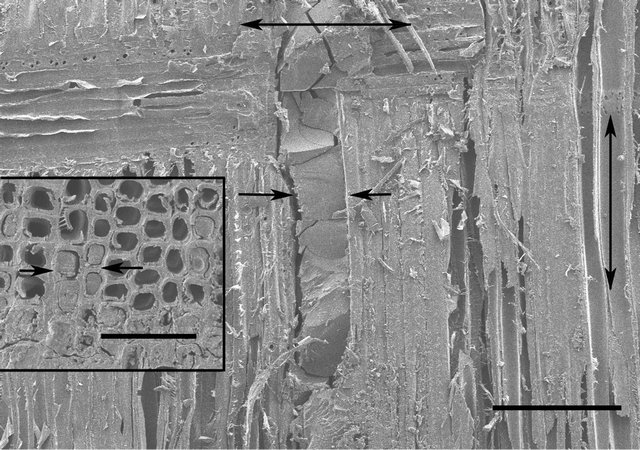
Figure 1. SEM micrograph of UF resin adhesive line (arrows) between paired wood veneer pieces. The vertical double headed arrow indicates the direction of wood grain and the horizontal double headed arrow indicates the direction in which ultrathin sections were cut. The region of wood tissues similar to that shown in the inset was trimmed for ultrathin sectioning. This region contains UF resin adhesive filled cells (arrows) in contact with and close vicinity to the adhesive line. Bar in Figure 1 = 250 µm; Bar in inset = 100 µm.
a glass slide for locating the UF resin adhesive bond line and selecting blocks where one end of the section was positioned closest to the conical tip of the block. The adhesive line was readily distinguishable from wood tissues, which facilitated selection of the sample region for trimming to obtain a block face suitable for smoothening with a glass knife. Final trimming was done to reduce the size of the block face to contain 6 - 8 wood cells, including those that were in contact with or near the adhesive line and were filled with UF resin adhesive. The blocks were sectioned with a diamond knife on an ultramicrotome to obtain 80 - 90 nm thick sections (it was not possible to cut any thinner sections without considerable distortion because of the extreme hardness of UF resin adhesive containing wood tissues). The sections were stained for 7 minutes with either 2% aqueous uranyl acetate or 2% uranyl acetate prepared in 50% ethanol. Aqueous uranyl acetate was slightly superior to alcoholic uranyl acetate in improving the contrast of UF resin microstructure, and therefore the images illustrated are based only on staining with aqueous uranyl acetate. Although the exact mechanism of uranyl acetate staining still remains unclear, it has been suggested that this reagent reacts with amino group, and this was the basis for selection of uranyl acetate for staining ultrathin sections, as UF resin is an aminoplastic resin. The sections were viewed with H-7100 Hitachi TEM operating at 75 kV.
2.5. Sample Preparation and Imaging with SEM
Micromorphological features of UF resin are also being investigated using SEM. However, here the sample preparation is only briefly described as SEM observation was not the main focus of the work reported, and the images illustrated (Figure 1) are only to show the adhesive line between the veneers and adhesive penetration into wood tissues.
Sections cut from UF resin adhesive glued veneers on a sliding microtome were mounted on SEM stubs using a carbon adhesive tape, coated with Osmium [14] and examined with S-4800 Hitachi FE-SEM at 5 kV.
3. Results and Discussion
The results presented are based on a novel sample preparation technique developed for TEM examination of ultrathin sections of UF resin. Although TEM has been widely used to examine ultrathin sections from a range of polymeric materials without embedding or after embedding in an embedding medium [5,9,15], UF resin has not been previously examined by TEM. This may be because UF resin becomes very hard and brittle upon curing. Although it has been possible to obtain ultrathin sections directly from polymeric materials in several TEM studies without the need for embedding them in an embedding medium [16-18], our initial attempt to trim pieces of thin UF resin films prepared for ultrathin sectioning was not successful, as the film was very brittle and turned powdery at the surface during trimming with a blade. Embedding UF resin films in Spurr’s resin for ultrathin sectioning also did not work, as the films were compact and un-penetrable by Spurr’s resin. The exact reason for resin compactness is not known; we assume that the release of water as a byproduct of reaction of urea with formaldehyde and its escape during resin curing may be responsible, as the resin is known to shrink greatly due to loss of water.
Knowing that it has been possible to obtain ultrathin sections from Spurr’s resin embedded wood tissues in contact with polyvinyl acetate (PVA) glue line in PVA bonded P. radiata boards [5], we prepared samples where pairs of small sheets of P. radiata wood veneers were glued with UF resin adhesive, as described in the materials and methods section (Figure 1). This approach worked, and it was possible to obtain ultrathin sections of Spurr’s resin embedded wood cells that were in contact with or in vicinity to the adhesive line and were filled with UF resin adhesive (Figure 1 inset). The reason why this method worked may be that UF resin contained within cell lumens is not likely to shrink much (if any) because the resin is physically constrained by the enclosing cell wall. Indications are that low molecular weight resins, including UF resin [19], can penetrate into wood and fiber cell walls. It is thus expected that the continuity of UF resin adhesive across cell lumen-cell wall will restrain the resin adhesive contained in the cell lumen from shrinking within the confines of the cell wall during curing. This could explain why it was possible to obtain ultrathin sections through UF resin adhesive mass contained within cell lumens, as Spurr’s resin would not only have penetrated cell walls but also the resin adhesive contained in cell lumens.
There are no previous reports of TEM studies of UF resin, and the novel sample preparation method developed is enabling us to undertake a TEM imaging based comparison of the microstructure of UF resins differing in the proportions of formaldehyde to urea (FU mole ratios) and also curing methods, such as the level of hardener used to accelerate the curing process. Here we illustrate images from TEM examination of ultrathin sections cut through UF resin adhesive contained within the lumens of cells located close to and in contact with the adhesive line (Figure 1).
We are investigating the microstructure of UF resin of a range of FU mole ratios cured using different levels of the hardener (NH4Cl), but the illustrations presented are of the UF resin of only two FU mole ratios, selected to represent a low (FU mole ratio 1.2) and a high (FU mole ratio 1.4) mole ratio, that differ greatly in their micromorphological features. In the image depicted in Figure 2, from a section taken through 1.2 FU mole ratio resin, spherical particles that have positively reacted with uranyl acetate and vary greatly in their size densely fill the lumen of the wood cell sectioned. In the higher magnification view of the boxed region in Figure 2 presented in Figure 3, several particles appear to be in close contact with each other, arranged linearly and in other formations, and indications are that they may be coalescing. In the image depicted in Figure 4 from a section taken through 1.4 FU mole ratio resin, spherical particles are also present; however, the particles are more uniform in their size and shape and far fewer in number compared to the 1.2 mole ratio resin. The particles have a similar morphology to the structures visualized in a few previous studies of UF resin employing SEM and described as spherical structures [1,4]. Our observations confirm the presence of such structures in UF resin by TEM, and support the proposed colloidal characteristics of this resin [20,21].
During curing, UF resin undergoes cross-linking reactions, and it is considered that higher mole ratio resins are more highly cross linked than lower mole ratio resins. The exact relationship of spherical particles to changes occurring at the molecular level during curing of different mole ratio UF resins is not fully understood. Presence of greater number of spherical particles in the 1.2 mole ratio UF resin than in 1.4 mole ratio resin suggests that there may be a link. Lower mole ratio UF resins are considered to be less cross linked than higher mole ratio UF resins, and this may be relevant in this regard. Our current work employing FE-SEM in combination with TEM to characterize the micromorphologies of liquid and
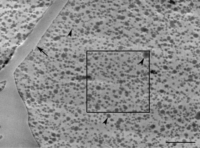
Figure 2. TEM micrograph of part of a cell containing UF resin adhesive (FU mole ratio 1.2) filled with different size spherical particles (arrowheads). The arrow indicates cell wall. The boxed region is shown at high magnification in Figure 3. Bar = 2.5 µm.
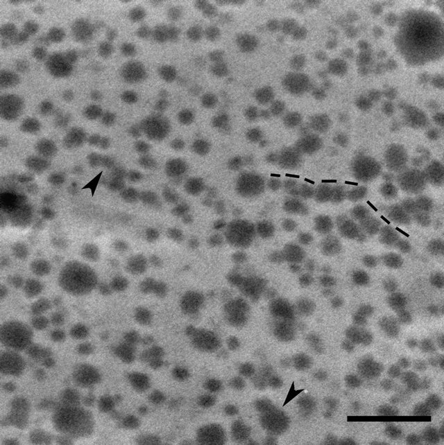
Figure 3. Higher magnification view of the boxed region in Figure 2. Linearly aligned particles (dotted lines) and the groups of particles shown at the arrowheads appear to be coalescing. Bar = 1 µm.
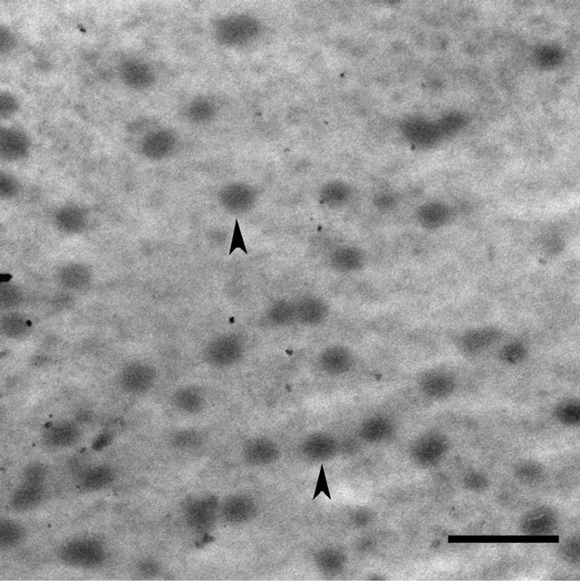
Figure 4. TEM micrograph of UF resin adhesive (FU mole ratio 1.4) containing spherical particles (arrowheads). Particles are more uniform in the size and morphology and are fewer in number than in 1.2 mole ratio resin adhesive (compare with Figure 3). Bar = 1 µm.
cured UF resins of different mole ratios and planned work involving high resolution chemical and physical characterization to understand the nano-architecture and molecular changes underlying the transformation of liquid to cured state UF resins may shed some light on the organization and functional relevance of the particulate phase of UF resin. In this regard, presence of greater amount of ordered crystallites in cured lower FU mole ratio UF resins than in higher mole ratio UF resins is of interest [22].
In conclusion, the novel sample preparation technique described made it possible to ultrathin section and examine for the first time cured UF resins by TEM, which will no doubt prove to be an important high resolution tool, filling the much needed gap in structural characterization in this area of work, that may be useful in developing formulations and processes to minimize formaldehyde emission from the UF resin in use as wood adhesive.
4. Acknowledgements
This work was supported by the Korean Ministry of Education, Science and Technology and the Korean Federation of Science and Technology Societies. This work was also supported by Basic Science Research Program through the National Research Foundation (NRF) of Korea funded by the Ministry of Education, Science and Technology (2011-0022112).
REFERENCES
- B. D. Park and H. W. Jeong, “Influence of Hydrolytic Degradation on the Morphology of Cured Urea-Formaldehyde Resins of Different Formaldehyde/Urea Mole ratios,” Journal of the Wood Science and Technology, Vol. 39, No. 2, 2011, pp. 179-186.
- A. Pizzi, L. Lipschitz and J. Valenzuela, “Theory and Practice of the Preparation of Low Formaldehyde Emission UF Adhesives,” Holzforschung, Vol. 48, No. 3, 1994, pp. 254-261. doi:10.1515/hfsg.1994.48.3.254
- J. Y. Gu, M. Higuchi, M. Morita and C. Y. Hse, “Synthetic Conditions and Chemical Structures of Urea-Formaldehyde Resins II. Synthetic Procedures Involving a Condensation Step under Strongly Acidic Conditions and the Properties of the Resins Obtained,” Mokkuzai Gakkaishi, Vol. 42, No. 2, 1996, pp. 149-156.
- J. Stuligross and J. A. Koutsky, “A Morphological Study of Urea-Formaldehyde Resins,” Journal of Adhesion, Vol. 18, No. 4, 1985, pp. 281-299. doi:10.1080/00218468508080464
- A. P. Singh, C. R. Anderson, J. M. Warnes and J. Matsumura, “The Effect of Planing on the Microscopic Structure of Pinus radiata Wood Cells in Relation to Penetration of PVA Glue,” Holz als Roh-und Werkstoff, Vol. 60, 2002, pp. 333-341.
- L. F. Drummy, J. Yang and D. C. Martin, “Low Voltage Electron Microscopy of Polymer and Organic Molecular Thin Films,” Ultramicroscopy, Vol. 99, No. 4, 2004, pp. 247-256. doi:10.1016/j.ultramic.2004.01.011
- K. Yamauchi, S. Akasaka, H. Hasegawa, S. Koizumi, C. Deeprasertkul, P. Laokijcharoen, J. Chamchang and A. Kornduangkaeo, “Structural Study of Natural Rubber Thermoplastic Elastomers and Their Composites with Carbon Black by Small-Angle Neutron Scattering and Transmission Electron Microscopy,” Composites Part A, Vol. 36, No. 4, 2005, pp. 423-429.
- T. Yoshioka, M. Tsuji, Y. Kawahara, S. Kohjiya, N. Manabe and Y. Yokota, “Morphological Study by TEM on Uniaxially Oriented Thin Films of PBT,” Polymer, Vol. 46, No. 14, 2005, pp. 4987-4990. doi:10.1016/j.polymer.2005.04.046
- L. Sawyer, D. T. Grubb and G. F. Meyers, “Polymer Microscopy,” 3rd Edition, Springer, New York, 2008.
- A. P. Singh, B. Dawson, C. Rickard, J. Bond and A. Singh, “Light, Confocal and Scanning Electron Microscopy of Wood-Adhesive Interface,” Microscopy and Analysis, Vol. 22, No. 3, 2008, pp. 5-8.
- R. Adhikari and G. H. Michler, “Polymer Nanocomposites Characterization by Microscopy,” Journal of Macromolecular Science, Part C: Polymer Reviews, Vol. 49, No. 3, 2009, pp. 141-180. doi:10.1080/15583720903048094
- G. E. Myers, “Hydrolytic Stability of Cured Urea-Formaldehyde Resins,” Wood Science, Vol. 15, No. 2, 1982, pp. 127-138.
- A. R. Spurr, “A Low-Viscosity Epoxy Resin Embedding Medium for Electron Microscopy,” Journal of Ultrastructure Research, Vol. 26, 1969, pp. 31-43. doi:10.1016/S0022-5320(69)90033-1
- E. Suzuki, “High-Resolution Scanning Electron Microscopy of Immunogold-Labelled Cells by the Use of Thin Plasma Coating of Osmium,” Journal of Microscopy, Vol. 208, No. 3, 2002, pp. 153-157. doi:10.1046/j.1365-2818.2002.01082.x
- O. Monticelli, Z. Musina, S. Russo and S. Bals, “On the Use of TEM in the Characterization of Nanocomposites,” Materials Letters, Vol. 61, No. 16, 2007, pp. 3446-3450.
- Y. Jiao and P. Akcora, “Assembly of Polymer-Grafted Magnetic Nanoparticles in Polymer Melts,” Macromolecules, Vol. 45, No. 8, 2012, pp. 3463-3470.
- P. M. Carrasco, L. Tzounis, F. J. Mompean, K. Strati, P. Georgopanos, M. Garcia-Hernandez, M. Stamm, G. Cabanero, I. Odriozola, A. Avgeropoulos and I. Garcia, “Thermoset Magnetic Materials Based on Poly(ionic liquid)s Block Copolymers,” Macromolecules, Vol. 46, No. 5, 2013, pp. 1860-1867. doi:10.1021/ma302261c
- S. Coiai, D. Prevosto, M. Bertololo, L. Conzatti, V. Causin, C. Pinzino and E. Passaglia, “Chemistry of Interfacial Interactions in a LDPE-Based Nanocomposite and Their Effect on the Nanoscale Hybrid Assembling,” Macromolecules, Vol. 46, No. 4, 2013, pp. 1563-1572.
- C. Xing, B. Riedl, A. Cloutier and S. M. Shaler, “Characterization of Urea-Formaldehyde Resin Penetration into Medium Density Fiberboard Fibers,” Wood Science and Technology, Vol. 39, No. 5, 2005, pp. 374-384. doi:10.1007/s00226-005-0294-4
- A. Despres and A. Pizzi, “Colloidal Aggregation of Aminoplastic Polycondensation Resins: Urea-Formaldehyde Versus Melamine-Formaldehyde and MelamineUrea-Formaldehyde Resins,” Journal of Applied Polymer Science, Vol. 100, No. 2, 2006, pp. 1406-1412. doi:10.1002/app.23230
- J. M. M. Ferra, A. M. Mendes, M. R. N. Costa, L. H. Carvalho and F. D. Magalhaes, “A Study on the Colliodal Nature of Urea-Formaldehyde Resins and Its Relation with Adhesive Performance,” Journal of Applied Polymer Science, Vol. 118, No. 4, 2010, pp. 1956-1968. doi:10.1002/app.31112
- B. D. Park and V. Causin, “Crystallinity and Domain Size of Cured Urea-Formaldehyde Resin Adhesives With Different Formaldehyde/Urea Mole Ratios,” European Polymer Journal, Vol. 49, No. 2, 2013, pp. 532-537.
NOTES
*Corresponding author.