Archaeological Discovery
Vol.07 No.04(2019), Article ID:94182,18 pages
10.4236/ad.2019.74010
The WWII Ringeltaube
Giancarlo T. Tomezzoli
Etno-Archaeological Observatory, Munich, Germany
![]()
Copyright © 2019 by author(s) and Scientific Research Publishing Inc.
This work is licensed under the Creative Commons Attribution International License (CC BY 4.0).
http://creativecommons.org/licenses/by/4.0/


Received: July 16, 2019; Accepted: August 4, 2019; Published: August 7, 2019
ABSTRACT
In literature, many articles, books and original documents deal separately with the WW II German project Ringeltaube giant components: Walnuß I, Weingut I, Weingut II. In doing so, they highlight the financial effort and the forced workers’ sufferings involved in the construction of each of them. This article dealing with Ringeltaube as a whole, estimates at 1,722,453,684$ of today its total bill and between 18,100 and 20,500 the forced workers died because of Ringeltaube. In addition, the architectural details, the constructional advancement and the preservation state of each component today at more than seventy years from the end of the WW II are presented.
Keywords:
Third Reich, WW II, Ringeltaube, Bedburg, Mühldorf, Landsberg, Kaufering, Biber, Weingut, Diana, Walnuß

1. Introduction
During the Casablanca Conference on January 1943, it was set the bases of the strategic Combined Bomber Offensive against the German Third Reich. Primary objective of the Offensive, culminated in the Operation Argument or Big Week on February 1944, was the German aircraft industries which represented the bigger portion of the industries involved in the war through the effort of about 400,000 workers, of which about 130,000 - 160,000 concentration camp (Konzentrationslager—KZ) inmates, and of about 10 Reichsmarks billions. 10,000 tons of bombs destroyed up to 75% of the aircraft plants and about 30% of the equipment. In March 1944 only one third of the expected German aircrafts was produced.
This and the necessity of increasing the number of aircrafts for controlling the air space caused the formation of the Fighter Staff (Jägerstab) in charge of speed up the fighter aircraft production and motivated the German Ministry of Armaments and War Production (Reichministerium fur Rustungs und Kriegsproduktion) and the Aviation Ministry (Reichsluftfahrtsministerium) to order the moving to central and southern Germany, where more concentrated protection could be offered, of industries involved in the production of the Messerschmitt Me 262, Dornier Do 335 and Focke-Wulf TA 152 aircrafts (Jägersprogramm). Twenty-seven major aircraft industries were planned to be moved in 729 smaller production shops hidden in mines, quarries, highway and railway tunnels.
However, confinement, humidity, raw materials and final products delivery problems led to the concept of locating all production within sheltered sites. This motivated Chancellor Hitler on 5th March 1944 to decide the centralization of the fighter aircraft production into six giant half-buried bunkers. In the period 19th-22nd April 1944 several high level meetings took place for defining the organization, priorities and security of the project which received the code name Ringeltaube (Wood Pigeon) and was put in charge to the Organization Todt (OT).
Each bunker site to be selected had to be rich in gravel and water supply for the bunker construction, heavily forested for their camouflage and near a railway station for material supply and delivery (Deiler, 2016; Müller, 2007; Odinius, 2004; Posset, 2016; Raim, 1992) .
2. Locations and Architecture
The selected sites were Bedburg in Rhineland: Walnuß I or Biber bunker, Mühldorf am Inn in Bavaria: Weingut I bunker, Landsberg am Lech in Bavaria: Weingut II, Diana II, Walnuß II bunkers and the Protectorate of Bohemia and Moravia or Sudetenland: Diana I bunker. The three bunkers near Landsberg were planned for the aircraft final assembly based on assembly lines. From there, the aircrafts had to use a makeshift runway for take-off to their destinations The Allied invasion of Normandy in June 1944 caused the restriction of Ringeltaube to Walnuß I, Weingut I and Weingut II.
The Jägersprogramm envisioned the production of over 900 of the more promising Me 262 per month. The production of various Me 262 parts had to be subdivided amongst Walnuß I, Weingut I and various, different local and foreign workshops while the final assembly concentrated to Weingut II.
The bunker project (Figure 1), based on the ground formwork (Erdschalung) concept, was developed by the OT chief executive Xaver Dorsch, on the basis of the projects of the V-weapons bunkers in France, for reducing formwork wood, facilitating the concrete casting and save construction costs.
Each bunker had to be about 400 m long, 85 m wide and 32.20 m high of which 13 m above ground and 19.20 m underground. The arcuate coverage was formed by 12 arches, each 33 m long, separated by a 30 cm gap to be filled at the coverage completion.
Soil and trees had to be removed for clearing out the bunker area. A removal tunnel (Entnahmetunnel), provided with silo valves at regular distances on its
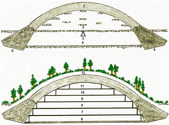
Figure 1. Bunker project: (1) arcuate coverage; (2) semi-cylindrical ground formwork; (3) removal tunnel; (4) final soil level; (5) concrete arch foundations; (6) 1st floor; (7) 2nd floor; (8) 3rd floor; (9) 4th floor; (10) 5th floor; (11) 6th floor; (12) forested layer (Start image Ehmke, 2005 ).
top, had to be dug into the original terrain along the central axis of the foreseen arches. Two trenches parallel to the tunnel had to be dug and concrete poured inside for creating the arch foundations. Once dried, gravel and earth had to be collected between the arch foundations and over the tunnel to form a semi-cylindrical ground formwork. It had to be smoothed and flattened for receiving a 30 cm thick concrete layer of the first arch. Metal rods had to be fixed on it for supporting a second 5 m thick concrete layer accumulated by means of cranes and pumps. Twenty days later when the concrete was dried, the ground formwork had to be removed from below the arch by means of a convoy entering the removal tunnel and parking the wagons under the silo valves. The silo valves opening caused the ground formwork gravel and earth to fill up the wagons. The original terrain had to be excavated up to the underground soil level. These operations had to be replicated up to the last arch. Over the bunker arcuate coverage obtained, a final 3 m forested layer had to be formed to provide camouflage. A 5 m thick wall provided with entrances had to close each bunker extremity. A construction provided with six to eight floors had to be built in the bunker interior (Ehmke, 2005; Müller, 2007; Odinius, 2004; Cocconcelli, 2002; Zaloga, 2012) .
3. Biber
The Biber (Beaver) site (50˚58'56.2''N, 6˚35'8.7''E) was near Bedburg, on the right side of the river Erft, in the Rheinbraun Fortuna brown coal open-cast mine (Figure 2). At its completion, Biber had to accommodate about 40 firm branches, which starting from March 1945, had to produce, on 110,000 m2 surface, military equipments such as electrical devices, cables, crankshafts, aircrafts devices. The site was selected by the OT Chief Construction Department (Chefkonstruktionabteilung) in Berlin because of its solid underground, a deep groundwater, a nearby gravel plant with large gravel and sand deposits, water supply through the Erft and a good connection with the German railway network (Reichsbahn) by the Bedburg railway station.
The bunker design was carried out by the OT department Hansa based in Essen. The overall management was assumed by the OT Operational Group Rhur, Supply Department (Einsatzgruppe Ruhr, Abtl. Nachschub) based in Essen-Heidhausen. Each arch foundation had a concrete volume of 7500 m3 and the total construction had a concrete volume of 300,000 m3. About 70 - 90 kg of steel were used per concrete cubic meter. Each arch was built by pouring the concrete in formwork boxes. Engineers of the OT constantly checked the concrete quality (B 225). Biber followed a project slightly different from that of the already started Weingut I in Mühldorfer Hart. Biber had to be 370 m long, 112.40 m wide with a concrete coverage 6 m thick. The coverage had to receive a 3-meter-thick ground layer. After each arch drying, a sand, gravel and ground thickness of 31 m had to be removed for the internal construction of 6 floors, each 4 m high. The 3rd floor corresponding to the original ground level had to be accessed by three rail lines for distribution of incoming raw material and shipping of finished pieces. The 6th floor had to host a kitchen, cantinas and a pantry for about 2060 workers.
Ground and concrete constructions had to be carried out by Butzer, Hoch-Tief AG and Rathjens firms, concrete and precast concrete sections by Weys & Freitag and Dyckerhoff & Widmann firms, transport and elevator systems

Figure 2. Biber area—A Federal highway 61; B: Bedburg; Bi: Biber site; Be: Bergheim; E: Erft; K: Kaster; L: Lipp; M: Millendorf; O: Oppendorf (Zoom Earth).
by Otis and Demag firms, ventilation systems by R.O. Meyer firm. The fans of Auer firm had to circulate 200,000 m3 air per hour. 36 air supply and exhaust systems, consisting of fans, air heaters and filters were planned. A gas protection of the entire system was not foreseen because several gas-proof rooms for the about 4000 workers had to be built inside the bunker. Ten transport lines for manufactured sections were foreseen. A further bunker 100 m long, site unknown, was planned for armament production.
In spring 1944, the entire right bank of the Erft between Bedburg and Bergheim was enclosed by barbed-wires controlled by guarded posts. Inside, KZ extended over 6 km for about 10,000 workers, although this number seems exaggerated, other workers were lodged in two KZ near Bedburg. An unprecedented number of construction machines (excavators, mixing machines, construction cranes) were collected. The site received a new rail line from the Bedburg railway station and the required amount of water through a pipeline from the Erft. Each day, two work shifts were on the site, each formed by 3000 - 4000 workers. These were mostly forced workers, among which Italian, Dutch, Polish and Russian POWs. The work conditions were miserable: up to 10 - 12 hours work time, insufficient food, no suitable work clothes, no wages, flogging also for minor transgressions. The nearby town inhabitants were unaware of Biber. Unauthorized accesses to the site, photographing and sabotage attempts caused life danger.
The construction material was delivered via the new rail line, while the gravel was transported by a camouflaged rail line from the gravel plant. In May-June 1944, two parallel trenches 370 m long were excavated. After smoothing and flattening, concrete was poured inside forming the Biber side foundations. Each arch was built, first 4.50 m thick, and then a further 1.50 m thick concrete layer was added.
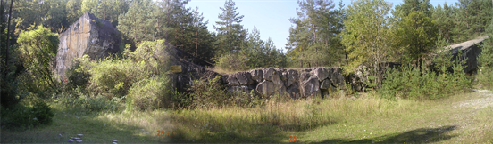
Due to the American advancing, at the beginning of 1945, the Biber construction, arrived up to the 2nd arch was stopped and the site abandoned. After the war, the Biber arches and foundations were removed to avoid them to hinder the work of big excavators in the open-cast mine. The arches and foundations were destroyed with explosives and the metallic armour cut. Concrete portions were disposed by trucks in the exploited part of the open-cast mine, which, later, was filled by terrain and re-cultivated. Why in 1944 Biber was planned so far to the west and not in central or southern Germany is unknown. The advantages of the Biber site, certainly have not weigh alone against the danger posed by the allied air. Biber as launcher of V2, as reported by witnesses, remains controversial. In mid-1970s, with the complete removal of the remains, no trace of Biber was visible (Ehmke, 2005; Depcik, 2006; Kanzler, 2003) . Therefore, no Biber site visit took place.
4. Weingut I
The Weingut I (Vineyard I) site (48˚14'25.6''N, 12˚27'8.2''W) was in Mühldorf Hart, on the left side of the river Inn (Figure 3). 600 OT employees in their

Figure 3. Weingut I area—(1) KZ Waldlager I; (2) KZ Waldlager II; (3) KZ Waldlager III; 4) KZ Waldlager IV in project; (5)-(6) KZ Waldlager V-VI; (7) KZ Waldlager VII in project; (8) mass grave; (9) KZ Mettenheim I; (10) KZ Mettenheim Hart Süd—Russian forced workers; (11) KZ Mettenheim Hart Süd—Russian voluntaries; (12) KZ Grümer; (13) KZ Ecksberg; A: Amping; E: Ebing; H: Mettenheim Hart; K: Kraiburg; I: Inn; IB: firm Innbau Beton; Ik: Innkanal; M: Mühldorf; MH: Mühldorf Hart; WI: Weingut I site (Zoom Earth).
offices in Ampfing, Mettenheim and Ecksberg, were responsible for the planning and supervision of Weingut I construction as well as the work subcontracting to different firms, primarily Polensky & Zöllner (PZ) which was commissioned for the construction.
PZ transferred 200 workers and equipments from various parts of occupied Europe on the Weingut I site. 70% - 80% of PZ construction capacity was devoted to the Jagersprogramm. PZ received no formal contract from OT.
The Schutzstaffel (SS) supplied workers to OT and PZ and managed their work. Concentration camps were KZ Waldlager I-III for forced workers, KZ Waldlager V-VI, KZ Mittergars, KZ Thalham and KZ Gensdorf which formed the Mühldorf Ring named also Mühldorf Group or KZ Mühldorf. Other concentration camps were KZ Mettenheim I, KZ Ampfing, KZ Grümer, KZ Ecksberg and two KZ.
Mettenheim and two KZ Mettenheim Hart Sud, one for Russian forced workers and one for Russian voluntaries. Approximately 8.300 inmates were in these camps from July 1944 to April 1945. They were Hungarians, Polish, Greeks, Czechs, Yugoslavs, Lithuanians, Italians, Dutch, and Frenchs by nationality and Jews, POWs, KZ Dachau and KZ Auschwitz inmates, political prisoners and voluntary workers by category. They were in general classified auxiliary workers (Hilfsarbeiter). Their payment was 60 Pfennigs per hour due at the end of each month, but they never received payment. Overwork combined with beatings, starvation diet, unsanitary living conditions and disregard for medical needs resulted in the death of 1800 - 3000 forced workers. The life expectancy was 40 - 60 days.
The Weingut I site was requisitioned and mid May 1944. Facilities were soon constructed comprising a carpentry, a cement shop and a cement brick bakery. The site was selected because of a nearby gravel plant with large gravel and sand deposits and water supply through the Innkanal. Light Flak artillery was onsite against low-flying enemy aircrafts. A fake construction site was built between Altötting and Burghausen for diverting the Allied air reconnaissance. A rail track was built between Mühldorf and Munich for the materials transport. A planned rail connection between Mühldorf and Rosenheim never took place. Rails gone from the onsite concrete depot to the Weingut I site.
The removal tunnel was parabolic shaped, 5 m high and consisted of precast hinged arches for reducing iron and concrete. The internal construction had 250,000 m2 production area on nine levels. Plans were also drawn up for install stairs, elevators and pillars, all made by precast sections that had been assembled in workshops in Ampfing and Mittergars. However, these plans were never accomplished due to the worsening of the war situation.
Near the WW II end, PZ sent a bill of 25,867,592 RM (Reichsmarks) that OT refused to pay because of the worsening of the war situation.
At the end of April 1945, only arches 1 to 7 of the originally planned 12 were completed. Disruptions in the supply of materials and lack of skilled workers delayed Weingut I which was never bombed. The US Army in 1946 used 125 tons of TNT for demolishing Weingut I. This for testing Weingut I resistance to a full-scale bombing (Bankel, 2009; Müller, 2007; Paul, 1981).
5. Weingut I Visits
The Weingut I visits took place on 27th February 2005, 25th September 2005, 12th March 2016 and 4th May 2019. The access path started near the firm Innbau Beton (Figure 3) and proceeded in the forest up to the Weingut I site.
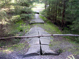
The 1st arch lay on the ground. Its structure was seriously fractured. Its front side showed that the collapse fragmented the arch in concrete blocks in the middle, larger blocks at the sides and two portions still in place at the extremities. Its rear side was masked by the 2nd arch front side. On its coverage formwork element traces and parallel aligned armour iron extremities, about 10 - 30 cm high, were well visible. Small plants grew sparse on its coverage (Figures 4(1)-(4)).
The 2nd arch lay on the ground. Its structure was seriously fractured. Its front and rear sides were masked respectively by 1st arch rear side and the 3rd arch front side. Two portions were still in their original position at its extremities. On its coverage formwork element traces and parallel aligned armour iron extremities were well visible. Young plants grew sparse on its coverage (Figures 4(4)-(5)).
The 3rd arch lay on the ground. Its structure was seriously fractured. Its front and rear sides were masked respectively by the 2nd arch rear side and the 4th arch
 (1)
(1)
 (2)
(2)
 (3)
(3)
 (4)
(4)
 (5)
(5)
Figure 4. Weingut I—(1) 1st arch, overview; (2) front side; (3) coverage; (4) 1st and 2nd arches bases and details of the vegetation on the upper surface of the 2nd arch; (5) 2nd arch, fractured coverage with aligned extremities of the armour irons.
front side. On its coverage formwork element traces and parallel aligned armour iron extremities were well visible. Young plants grew sparse on its coverage (Figure 5(1)).
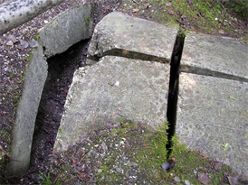
The 4th arch lay on the ground. Its structure was seriously fractured. Its front and rear sides were masked respectively by the 3rd arch rear side and the 5th arch front side. On its coverage formwork element traces and parallel aligned armour iron extremities were well visible. Young plants grew sparse on the coverage (Figure 5(2)).
The 5th arch lay on the ground. Its structure was seriously fractured. Its front and rear sides were masked respectively by the 4th arch rear side and the 6th arch front side. On its coverage formwork element traces and parallel aligned armour iron extremities were well visible. Hardwoods and conifers grew sparse on its coverage (Figures 5(3)-(4)).
![]() (1)
(1)
![]() (2)
(2)
![]() (3)
(3)
![]() (4)
(4)
![]() (5)
(5)
![]() (6)
(6)
Figure 5. Weingut I—(1) 3rd arch fractured coverage with aligned armour iron extremities; (2) 4th arch fractured coverage with aligned armour iron extremities; (3) 5th arch fractured coverage; (4) 30 cm gap between the 4th and 5th arch; (5) 6th arch coverage with traces of the formwork elements and aligned armour iron extremities; (6) worker’s shoe prints on the 6th arch concrete.
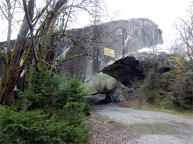
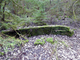
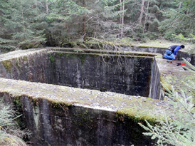
The 6th arch lay on the ground. Its structure was seriously fractured. Its front and rear sides were masked respectively by the 5th arch rear side and terrain debris. On its coverage formwork element traces and parallel aligned armour iron extremities were well visible. Particularly touching were shoe prints left by a worker on the concrete. Hardwoods and conifers grew sparse on its coverage (Figures 5(5)-(6), Figure 6).
The 7th arch survived the demolition and remained erected in its original position. Its front side toward the 6th and 5th arches clearly showed the 30 cm thick concrete layer supporting the 5 m thick concrete layer. Part of its rear side fallen on the ground letting an empty space on the arch and part remained attached to
![]() (1)
(1)
![]() (2)
(2)
![]() (3)
(3)
![]() (4)
(4)
 (5)
(5)
 (6)
(6)
Figure 6. Weingut I—7th arch: (1) coverage rear side with 30 cm and 5 m concrete layers, in the foreground 6th arch coverage; (2) coverage with constructive segments; (3) coverage with constructive segments and aligned vertical protrusions; (4) dynamite holes on the rear side; (5) rear side with empty space of the fallen part and attached part; (6) coverage with aligned armour iron extremities.
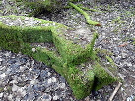
the arch because of the internal armour irons. On its coverage formwork element traces and parallel aligned armour iron extremities were well visible. At the arch interior the coverage showed parallel constructive segments. On a lower side, extending from a constructive segment, were three aligned vertical protrusions. Near the protrusions, a partially collapsed rear side preserved 20 holes about 10 cm in diam. Small plants grew sparse on its coverage (Figures 6(1)-(6), Figure 7).
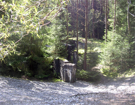
The removal tunnel emerging part departed from the 7th arch rear side for about 20 m toward West. It was formed by precast arches. The emerging arch portions were partially detached from each other by the internally accumulated

Figure 7. Weingut I—7th arch, front side overview from the 5th and 6th arches.
terrain pressure and the emerging silo valves were filled by concrete (Figures 8(1)-(3)). Each portion had a square hole about 10 × 10 cm, and was erected in its original position indicating a good preservation state of the buried arch. The removal tunnel entrance was buried in the terrain; therefore, the interior inspection was not possible. Tunnel precast arch components were laying on the nearby terrain (Figures 8(4)-(6)).
Traces of parallel foundations excavations were visible, but no traces of the ground formwork after the 7th were remarked.
A first and a second air intake/exhaust opposed to the Weingut I axis were identified. Each presented an external square wall about 20 × 20 m and 3 m high. Its concrete structure was in good preservation state showing construction formwork element traces. Armour iron extremities protruded from the upper portion. The internal square wall was about 10 × 10 m, about 3 m high and 2 m thick with lowered inner edges. Its concrete structure was in good preservation state showing construction formwork elements traces. The internal wall protected a well about 10 m deep with the floor inclined toward the Weingut I interior (Figures 9(1)-(4)).
Near the 7th arch rear side not far from the fallen and attached parts was an elongated rectangular concrete construction comprising a first entrance, a short corridor, a second entrance perpendicular to the first entrance and an internal elongated rectangular space. Its structure was in a good preservation state with traces of the construction formwork elements. The upper portion hosted protruding armour iron extremities (Figures 10(1)-(2)).
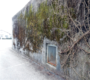
In the nearby Mühldorf, at about 5 km from Weingut I, on the site of the former PZ Workshop Mühldorf, now MBM Industrie GmbH, on 1943 PZ built an air-raid bunker (Luftschutzbunker, L-S bunker) (18˚14'44.7''N, 12˚20'25.1''E), 12 × 9 m (Figures 11(1)-(4)). It comprised 558.151 m3 concrete and 9111 kg of armour iron. Its basement was 1.20 m thick, the wall thickness 2 m, the coverage 2.50 m thick. The entrance had no anti-gas armoured door. The entrance corridor (a) joined a perpendicular corridor (b) at the end of which was an original armoured door provided with a circular hole grate. The door opened on a gas
 (1)
(1)
 (2)
(2)
 (3)
(3)
 (4)
(4)
 (5)
(5)
 (6)
(6)
Figure 8. Removal tunnel: (1)-(3) partially detached arches and concrete filled silo valves; (4)-(6) abandoned removal tunnel precast arches.
lock room (c) in connection with a 5.40 × 5.00 m main room (d) for the protection of up to fifty persons. On a side the main room had an emergency exit (e). The exterior and the interior structure were in a good preservation state without damages due to combats or bombardments. A construction (f) having an entrance and three windows, hanging on the bunker wall and opposed to the emergency exit wall, disappeared.
6. Weingut II
Despite the bombardments of Augsburg on 1942 and Munich on 24th-25th April 1944 which caused 70,000 homeless, in the period March-April 1944 it was decided to locate Weingut II, Diana II, Walnuß II in the nearby Landsberg area (Figure 12), although materials and workers had always to come from the exposed Augsburg and Munich areas.
 (1)
(1)
 (2)
(2)
 (3)
(3)
 (4)
(4)
Figure 9. Weingut I—(1) first air intake/exhaust, square internal wall; (2) well entrance toward Weingut I; (3) well inclined floor; (4) second air intake/exhaust.
 (1)
(1)  (2)
(2)
Figure 10. Weingut I—rectangular concrete construction: (1) entrances; (2) internal space.
However, Bavaria was not touched by combats, the roads and railway lines among Landsberg, Augsburg and Munich were still undamaged. The site was selected because it was a rural area without important military targets and its gravel layer, into which the bunker foundations had to be excavated and which provided gravel for the concrete, was sufficiently deep, the groundwater level was deep too and water was available from the Lech. In addition, the Bayerische Wasserkraft AG (Bawag) could provide electricity, the Dynamit Aktiengesellschaft (DAG) bomb explosives and ammunitions and the nearby Lagerlechfeld air field a place for testing the finished Me 262s.
 (1)
(1)
 (2)
(2)
 (3)
(3)
 (4)
(4)
Figure 11. L-S bunker—(1) overview; (2) front side with entrance; (3) bunker plan: (a) entrance corridor, (b) perpendicular corridor, (c) gas lock room, (d) main room, (e) emergency exit, (f) annexed construction; (4) emergency exit, details.
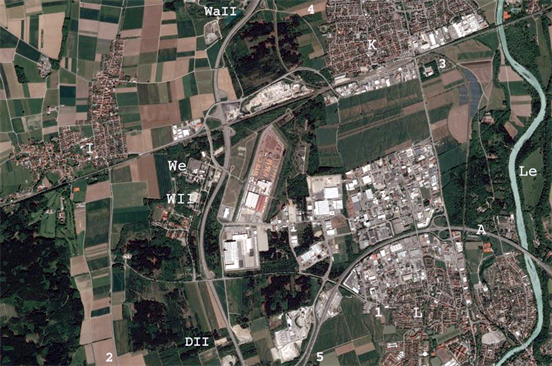
Figure 12. Weingut II area—(1) KZ Kaufering I; (2) KZ Kaufering II; (3) KZ Kaufering III; (4) KZ Kaufering IV; (5) KZ Kaufering XI; A Federal Highway 96; DII: Diana II site; K: Kaufering; L: Landsberg am Lech; Le: Lech; I: Igling; WII: Weingut II site; WaII: Walnuß II site; We: Welfen Barrack (Zoom Earth).
OT mobilized 2000 - 3000 workers in service on the Atlantic Wall for the Weingut II construction, commissioned Weingut II construction to firm Moll and supervised the construction until the end of March 1945. Weingut II had to be delivered on 31st November 1944 and designated for the final assembly of the Me 262s, while Weingut I was designated for the production of the motors and other components.
On 15th May 1944 firm Moll started to clear the 230,000 m2 of wood of the Weingut II site (48˚04'07.4"N, 10˚49'32.5"E) near Kaufering. Ten day after started the excavation of the Weingut II foundations. One million cubic meters of terrain had to be removed and 310,000 m3 of concrete to be used for foundations and coverage. Firm Moll calculated 20,179,700 RM the Weingut II cost. On 20 June 1944 the first thousands of Hungarian Jews arrived at the Kaufering station from the KZ Auschwitz. They were lodged in KZs around Kaufering and Landsberg built by OT. More than 13,000 forced laborers on the total of 22,000 workers employed were KZ Auschwitz Jewish inmates. In total 11 KZs were built, eight near Landsberg and Kaufering, two near Utting and one near Türkheim. The SS assumption of the direction of the Kaufering/Landsberg KZs caused a rapid increasing of inmates deaths through the annihilation by work (Vernichtung durch Arbeit). About 14,500 inmates died in the Kaufering/Landsberg KZs.
At April 1945, 200 m, i.e. seven arches, of Weingut II were built and half of the ground formwork removed through a rectangular, heavily dimensioned removal tunnel which hosted two rail.
At the beginning of May 1945, the Mühldorf district was liberated by the 47th US Tank Battalion of the 14th Division and the Weingut II site was placed under the US military administration. After the WW II, an unsuccessful attempt was made to demolish Weingut II and after it was used as ammunition depot. From 1960 to 1966 it was completed and adapted to protect components of the Matador flying bomb system. After the Matador decommissioning, since 1964 Weingut II was used by the German air force alone. Nuclear warheads were never stored inside. The bunker was further modified for hosting a storage and repair depot, a maintenance unit for avionic equipment, an air force materiel depot, and since 1980 an air force programming centre for airborne weapon systems (Posset, 2016; Odinius, 2004; Bankel, 2009) .
7. Weingut II Visit
The Weingut II visit took place on 15 April 2002 guided by commander Odinius. Weingut II was on the area of the Welfen Barrack near Landsberg and therefore, taking images was not allowed. It was covered by a forested layer, as foreseen by the original project, and was practically invisible. It appeared not hosting ongoing military activities, but it is possible that sensitive areas were excluded from the visit. The interior was accessible through a lateral entrance. A white painted corridor brought to the Military History Collection Memorial Weingut II (Militärgeschichtliche Sammlung Erinnerungsort Weingut II) where the history, architecture and sufferings of the workers were evocated. Commander Odinius declared that those were the last Weingut II days because it had to be closed so as to be one of the most obscure places in the world. A circular magnesium door, about 3 m in diam. and 1 m thick, was visible on a side of the exit corridor toward one main exit adapted for discharging vehicles.
8. Diana I, Diana II and Walnuß II
The Diana I site in the Sudetenland was not precisely defined (Raim, 1992) and the researches made did not provided its site location. Therefore, no visit took place.
At the end of November 1944 firm Stöhr, commissioned for Walnuß II construction, stopped the excavations and firm Holzmann, commissioned for Diana II construction, stopped the excavations (Posset, 2016; Odinius, 2004) . The researches made provided no information about construction remains. Therefore, no visit took place.
9. Discussion
Ringeltaube was part of the general German effort to protect sensitive installations in caverns, caves and bunkers. Beginning in 1943, began extensive construction projects within the occupied states and the Reich against air raids: the extended air-raid bunkers (erweitertes LS-Führerprogramm), the V-weapons sheltered sites (Wizernes, Éperleques, Mimoyecques, Villaine-la-Carelle (Tomezzoli & Pottier, 2015) and the Geilenberg-Programm).
At the beginning, probably, each of Diana I, Walnuß I, Weingut I and the corresponding Diana II, Walnuß II and Weingut II were dedicated to the component production and finishing of respectively the Me 262, Do 335 and TA 152. The decision to produce only the more promising Me 262 restricted Ringeltaube to the construction of Weingut I and Weingut II.
Biber at the WW II end, was in an initial construction state with two arches already in place. The literature available let unknown the shape of its removal tunnel.
Weingut I, at the WW II end, was in a relatively advanced construction state with seven arches already in place, i.e. about 210 m in length on the total of 400 m planned. Images taken at the end of the WW II showed that the formwork under the first seven arches was already removed and the formwork for the following arches already in place. The six arches lying on the terrain and the empty 7th arch confirm that the ground formwork was removed up to the level of the original terrain. The constructive segments remarked on the coverage of the 7th arch correspond to the subsequent concrete casting construction of the arch. The aligned protrusions inside the 7th arch were probably references for a floor of the internal construction. The 20 holes on the outer edge of the rear side of the 7th arch hosted or had to host sticks of dynamite. The whole demolition technics and the reason for which it failed in the case of the 7th arch are unknown. The removal tunnel was dry built without concrete for joining and fixing the precast arches. The square hole of each precast arch allowed its handling. The short aligned armour iron extremities on each arch coverage appear insufficient for fixing in place the corresponding forested layer. The protruding armour iron extremities on the upper portion of the external wall of the two air intake/exhaust and the upper portion walls of the elongated rectangular construction were probably intended for supporting and fixing upper structures. The Weingut I electrical power supply came probably came from the Töging power plant (Kraftwerk) at the end of the Innkanal (Ik) (Figure 3). A monumental conversion project for preserving the Weingut I remains was formulated in the past, but not yet been started. Therefore, in few decades it is possible that only the 7th arch will be visible.
The bunker in the nearby Mühldorf was a special construction (Sonderkonstruction) similar to Regelbau R 501. Its position on the parking of firm MBM Industrie GmbH ensures a long term preservation, although the annexed construction hanging on a wall disappeared for letting space to the actual Münchner road.
Weingut II, at the WW II end, was in a relatively advanced construction state with seven arches in place. Images taken at the end of the WW II showed that the formwork under the arches was already removed; no formwork was in place for the following arches and the wall for closing one of the bunker extremities was already started. The visit did not allow acquiring details of its internal construction and its floor organisation. The circular magnesium door assured radiation protection in case of nuclear attack. Notwithstanding the announcement of closure, Weingut II is today still open for visits.
Bearing in mind the 25,867,592 RM Weingut I bill presented, at the WW II end, by PZ to OT, the 20,179,700 RM Weingut II bill (Raim, 1992) , assuming a similar Biber bill and ignoring the Diana I, Diana II and Walnuß II bills, it is possible to estimate at about 66,226,992 RM (1938), corresponding to 1,722,453,684$ of today (Marcuse, 2005) , the lower limit of the Ringeltaube bill. Note that, this amount is only a conversion value, with the modern constructional technologies the amount may be inferior, but the exact amount remains to be determined.
Bearing in mind the 14500 dead workers at Weingut II, the 1800 - 3000 at Weingut I, assuming a similar number at Biber and ignoring the Diana I, Diana II and Walnuß II possible other dead workers, it is possible to estimate between 18100 and 20500 the forced workers dead because of Ringeltaube.
10. Conclusion
This article, dealing with Ringeltaube as a whole, highlighted constructional aspects of its giant components and estimated its bill both in financial and suffering terms. Therefore, it represents a solid base for further Ringeltaube studies.
Acknowledgements
The author thanks commander Odinius for the guided visit on the Weingut II site and Mr Haas and Mr Petschko for their researches respectively at the Bundes Archiv Militär Archiv (BAMA) in Freiburg and at the Militär Archiv in Berlin.
Conflicts of Interest
The author declares no conflicts of interest regarding the publication of this paper.
Cite this paper
Tomezzoli, G. T. (2019). The WWII Ringeltaube. Archaeological Discovery, 7, 193-210. https://doi.org/10.4236/ad.2019.74010
References
- 1. Bankel, H. (2009). A German War Plant from 1944/45: The Aircraft Factory Weingut I and the Concentration Camp Waldlager 6 near Mühldorf/Inn. In Proceedings of the Third International Congress on Construction History (pp. 107-118). Cottbus. [Paper reference 2]
- 2. Cocconcelli, G. D. (2002). Tunnel factories: Le officine aeronautiche Caproni e Fiat nell’Alto Garda 1943-1945 (2nd ed.). [Paper reference 1]
- 3. Deiler, M. (2016). Messerschmitt 262-Dornier 335-Focke-Wulf Ta 152. Flugzeuge, die in den Rüstungsbauten um Landsberg gebaut werden sollten. Europäische Holocaustgedenkstätte. Stiftung e.V.http://www.landsberger-zeitgeschichte.de/Geschichte/ruestung/Flugzeuge.htm [Paper reference 1]
- 4. Depcik, U. (2006). Die Organisation Todt. Bunkerbau in Bedburg. Historicum.net. Fachinformationsdienst Geschichtswissenschaft.https://www.historicum.net/de/themen/zwangsarbeit-rhein-erft-rur/aufsaetze/artikel/die-organisatio [Paper reference 1]
- 5. Ehmke, A. (2005). Z-Werk BIBER in Bedburg/Erft, DAWA Nachrichten, Ausgabe 45, 16-20 Verlag Harry Lippmann, Köln, 1. [Paper reference 3]
- 6. Kanzler, H.-L. (2003). Das OT-Gelände in Bedburg. Tausende Gefangene schufteten am “Biber”. Kölnische Rundschau 31. Mai 2003.http://www.wisoveg.de/bedburg/zwangsarbeit/otb4.html [Paper reference 1]
- 7. Marcuse, H. (2005). Historical Dollar-to-Marks Currency Conversion Page. http://marcuse.faculty.history.ucsb.edu/projects/currency.htm [Paper reference 1]
- 8. Müller, P. (2007). The Bunker Complex in the Mühldorfer Hart: An Arms Race and Human Suffering (Translated by Wimmer, C.). http://www.kz-gedenk-mdf.de/bunker-complex-muehldorfer-hart [Paper reference 3]
- 9. Odinius, F.-W. (2004). The English Version of Project Ringeltaube. Waffensystemunterstützungzentrum. Landsberg/Kaufering. [Paper reference 4]
- 10. Paul, K. D. (1981). United States Army Investigation and Trial Records of War Criminals. United States of America v. Franz Auer et al. November 1943-July 1958. National Archives Microfilm Publications. Pamphlet Describing M1093.
- 11. Posset, A. (2016). Deckname “Ringeltaube”. über die Entstehung der OT-Rüstungsbauten unter der Oberbauleitung Ringeltaube in den Jahren 1944/45. Europäische Holocaustgedenkstätte. Stiftung E.V. http://www.landsberger-zeitgeschichte.de/Geschichte/ruestung/OBL.htm [Paper reference 3]
- 12. Raim, E. (1992). Die Dachauer KZ-Außenkommandos Kaufering und Mühldorf. Rustungsbauten und Zwangsarbeit im letzten Kriegsjahr 1944/45. Landsberger Verlaganstalt Martin Neumayer. Landsberg a. Lech. [Paper reference 3]
- 13. Tomezzoli, G., & Pottier, L. (2015). Die deutschen militärlogistischen Anlagen westlich von Mamers, DAWA Nachrichten, Ausgabe 65, 14-27. Köln: Verlag Harry Lippmann. [Paper reference 1]
- 14. Zaloga, S. J. (2012). Defense of the Third Reich: 1941-45. Oxford: Osprey Publishing. [Paper reference 1]