Geomaterials
Vol.08 No.03(2018), Article ID:86257,11 pages
10.4236/gm.2018.83003
Taking into Account the Effect of Dual Wheels on the Behavior of Lateritic Gravelly Pavements
Baye Birane Thiam1, Fatou Samb2, Adama Dione1
1Laboratoire de Mécanique et Modélisation, UFR Sciences de l’Ingénieur, Université de Thiès, Thiès, Sénégal
2Chef Département géotechnique, UFR Sciences de l’Ingénieur, Université de Thiès, Thiès, Sénégal

Copyright © 2018 by authors and Scientific Research Publishing Inc.
This work is licensed under the Creative Commons Attribution International License (CC BY 4.0).
http://creativecommons.org/licenses/by/4.0/


Received: April 21, 2018; Accepted: July 24, 2018; Published: July 27, 2018
ABSTRACT
The representation in the three-dimensional space of the physical model symbolized by the application of the pairing of the wheels described by 2 disks with a radius of 0.125 m and a 0.375 m spacing has the advantage of more accurately simulating the loading. In most cases, the assumption of a uniform distribution of loading on the circular surface is considered. In order to determine the effect of dual wheels, this research proposes a new approach to the distribution of vertical contact stress in three-dimensional space with loading on the circular surface. This allowed evaluating the maximum deformation on the space described by the dual wheels. The results showed that vertical deformation is maximum at the center of each circular surface. The distribution of the vertical contact stress is non-uniform on the circular footprint and has a significant influence on the deformation of the pavement at the level of the bituminous layer. The impact assessment of the twinning reveals that the dual wheels load causes less damage than that of a single wheel. These results are obtained by means of a numerical simulation under Cast3M with a gravitational lateritic pavement.
Keywords:
Dual Wheels, Circular Surface, Single Axle with Dual Wheels, Lateritic Gravelly, Cast3M

1. Introduction
The impact assessment of the twinning reveals that the dual wheels load causes less damage than that of a single wheel pavement design methods; it is generally assumed that the contact pressure is static and equal to the inflation pressure [1]. This vertical contact pressure is evenly distributed over two circular disks representing the load. However, roads are subject to repeated load variations generating constraints that can be detrimental to their durability. Traffic loads can be represented by a repeated loading cycle to simulate the effect of traffic. It is necessary to have a modeling allowing introducing the parameters of the materials as well as their behavior and having a three-dimensional representation of the geometry to simulate more faithful way for the loading.
The present research aims to propose a new approach to the distribution of the vertical contact stress in three-dimensional space with the loading on the circular surface. In addition, an analysis of the evolution of the deformation as a function of depth will be used to better understand the distribution. The implementation of this one will make it possible to quantify the maximum deformation and to pronounce on the effect of the dual wheels. The studies conducted as part of this work are essentially based on a numerical simulation using the Cast3M finite element calculation coding.
In this paper, we present some results from modeling to evaluate the influence of two parameters: axle configuration impact and vertical stress distribution. The results of the simulation, which will be discussed regarding the distribution of the vertical contact stress, also make it possible to study the impact of twinning.
2. Problem Related to Traffic Charges
Factors taken into account in the traffic analysis are essentially the axle load, the axle configuration and the number of axle applications [2].
2.1. The Impact of Axle Configuration
Traffic loads are applied to roadways by means of tires. These tires may consist of single or dual wheels. Most axle configurations are used (single axle, tandem axle and tridem axle).
Single axle: isolated axle (single wheel or dual wheels) whose axis is more than 2m distant from any axle of the vehicle.
Tandem axle: axle belonging to a group of two axles whose distance from the axles is less than 2 m.
Tridem axle: axle belonging to a group of three axles whose distance from the axes is less than 2 m.
The number and spacing of axles are the determining factors for the transmission of loads to the pavement. The increase in the number of axles reduces the load transmitted to the pavement at equal load [3]. The deformations obtained under a single-wheel load are much greater than the deformations obtained under dual wheel loading through the response of various types of soft pavement [4]. A loaded, single-axle heavy-duty truck degrades road pavement more than a truckload with dual wheels [5]. There is a big difference between the various wheel types. Single wheels causes more damage because of the increase in contact pressures that they generate [6]. Indeed, a single axle produces more damage than a tandem axle. Likewise, a tridem axle produces less damage than a tandem axle [7].
2.2. The Distribution of the Vertical Contact Stress
The distribution of contact pressures depends mainly on the type of tire, the load applied and the inflation pressure. In 1989, [8] reported that under-inflated and overloaded tires cause edge pressures to increase while over-inflation tends to concentrate maximum pressures in the center. [9] has achieved the real distribution of tire contact pressures thanks to the Vehicle-Road Surface Pressure Transducer Array (VRSPTA). These results confirmed most of the observations made by [8]. [9] showed that the vertical contact stress is not uniform. From the measurements, they concluded that overloaded and underinflated tires induce vertical overpressures in the edges, while over-inflation tends to concentrate the maximum pressures in the center. They argued that the tire load does not significantly affect the development of the vertical stress in the central area of the tire footprint as opposed to the outer areas of the footprint. [10] investigated in detail the non-uniformity of the tire impression pressure. He divided the footprint into two zones: an outer zone representing 40% of the total area and a central area representing 60% of the total area. He concluded that the load does not significantly affect the development of contact stresses in the central area of the tire. It also shows that the tire inflation pressure strongly affects the stress in the central zone. Other authors like [11] [12] [13] , also showed that the vertical contact stress is not uniform.
3. Modeling the Effect of Dual Wheels on Lateritic Gravelly Pavements
3.1. Presentation of the Model
To take into account the non-linearity of the foundation and base layers, and to evaluate the impact of the overload, [14] has established a numerical model using a finite element calculation code Cast3M. The algorithm that allows us to implement the model to model the reversible behavior of pavement materials is given in Figure 1. The pavement used consists of lateritic material and is modeled in 2D. With these materials, the effect of a single wheel has been tested by [14]. To know the actual behavior of the roadway in the event of an overload, the effect of twinning must be taken into account. The configuration of this load (2disks spaced) does not allow modeling the whole structure-loading in 2D [15]. In addition, to know the deformations and the real deflections, one can also be interested in the modeling of the physical model symbolized by the application of a pairing of the wheels. This 3D modeling has the advantage of simulating more accurately the loading.
Based on the work of [14] [16] has again established a numerical model using a finite element calculation code Cast3M. This last allows to have the representation the loading of the wheels twinned in 3D space to assess the impact of axle configurations on untreated gravelly pavements. This model serves as a basis for studying the effect of dual wheels on lateritic pavements.
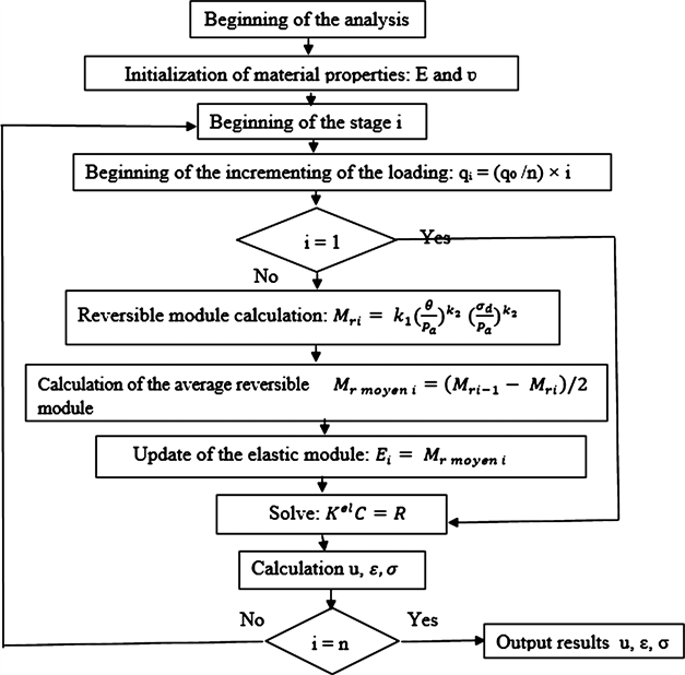
Figure 1. Algorithm of calculation used for the implementation of the model of Uzan [14].
3.2. Structure of the Modeled Roadway: Characteristics of the Materials―Geometry of the Model and Mesh―Loadings―Boundary Conditions
The modeling of a structure leads, in general, to be interested in several aspects of which the most usual is the geometry and its discretization. The modeling is based on a 3D structure of flexible pavement, consisting of a surface layer made of 80 mm thick bituminous materials, a lateritic gravelly basecoat treated with 2% cement of 250 mm thickness, a laterite gravelly foundation layer of 250 mm thickness and a platform of infinite thickness. The simulations were performed considering the hypothesis of the non-linearity of the base layer and that of the foundation, while the bituminous layer and the platform have a linear behavior. The input parameters obtained by [14] on the lateritic gravel of Ngoundiane are presented in Table 1 and used as a working tool for modeling.
The construction of the finite element model under Cast3M is done in this study using elements at 8 knots (cub8) on a quarter of the pavement. The carriageway is loaded with a half-axle with two (2) dual wheels spaced 37.5 cm apart and a single wheel with a radius of 12.5 cm. The charges will be applied to finely meshed fingerprints located at the surface layer. The description of this geometry has been adopted by [16] , who referred to the work of [14] for the optimal dimensions chosen. As part of this work, the reference axle is the single dual wheels 130 KN, used to represent the reference load during mechanical calculation. The loading is carried out considering a half axle with single wheel and another with dual wheels to evaluate the impact of the distribution of the load for each configuration.
The loading of a half-axle is equal to 65 KN. This load will be distributed and applied to the two finely meshed fingerprints located at the surface layer. For the one wheel one, it is the totality of this load that is applied. For the boundary conditions, the horizontal displacements are blocked in the transverse directions and the vertical and horizontal displacements are blocked in the lower part of the platform.
The images of the 3D mesh of each structure are given in Figure 2 and Figure 3.

Table 1. Characteristics of the lateritic gravel of Ngoundiane [14].

Figure 2. Mesh of the structure of roadway with loading of a single wheel.

Figure 3. Mesh of the structure roadway with loading of dual wheels [16].
3.3. Methodology
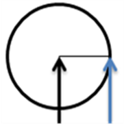
The modeling first focuses on the study of the distribution of the vertical stress and the impact of the configuration of the axles on the pavements. In the context of this simulation, the distribution of the vertical contact stress is studied by considering two (2) loading cases of a half-axle equal to 65 KN. For a one-wheel load, it is the totality of this load that is applied. The evaluation of the deformation will take place at the center of the circular imprint and also on a point of the circle (edge). For dual wheels, this load will be distributed over the two (2) circular impressions. The evolution of deformation over three (3) points (center, edge and plumb) will be examined as shown in Figure 4(b).
The impact of the axle configuration on the pavements is evaluated by considering a single and a dual wheel axle. The loading of a half-axle used is equal to 65 KN. The roadway is loaded with a semi-axle with dual wheels spaced 37.5 cm and a single wheel radius equal to 12.5 cm.
For this, we will represent the deformation at each layer of the roadway to better understand the distribution of the vertical stress.
3.4. Analysis and Interpretation of the Results
3.4.1. Distribution of Vertical Contact Stress
The deformations obtained at each layer, for the single wheel, are presented in Figure 5. Those obtained under the impression of a dual wheel are given in the following Figure 6.
The results obtained in the two (2) loading cases show that the evolution of the deformations in the center of the impression differs from that of the edge of the impression. Deformation is substantially greater at the center of the footprint than at the edge for all layers of the roadway except the platform. For each loading case studied here, the difference between the vertical deformation at the center and that at the edge is very considerable at the level of the bituminous layer. It decreases according to the depth of the layer at the level of the roadway. This may be due to the fact that the effect of the load decreases with the depth and distance of the area requested. However, it is important to note that the opposite trend is observed at the bottom of the foundation layer to a certain depth of the platform. This may be related to several factors (material properties, interface
 (a)
(a)
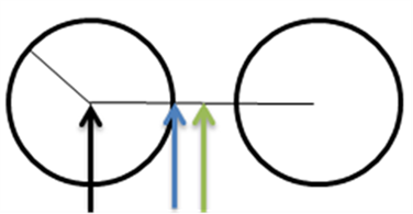 (b) Center; Edge; plumb
Figure 4. Schematic of the loading: (a) a single wheel; (b) 2 dual wheels.
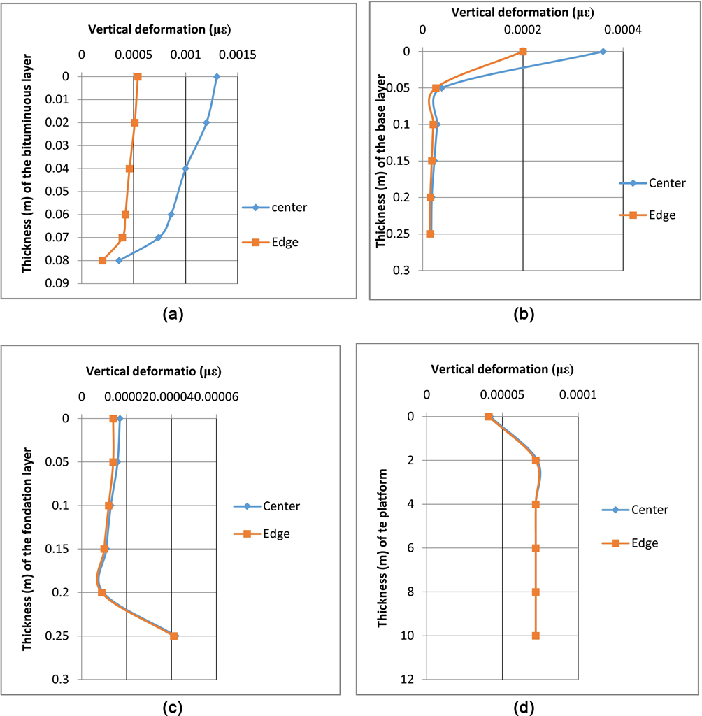
Figure 5. Evolution of vertical deformation at level: (a) bituminous layer, (b) base layer, (c) foundation layer, (d) platform; with the loading of a single wheel.
phenomenon, etc.) that are not covered in this study.
At the platform level, the evolution of the deformation on the different points considered remains the same for the two loadings (single wheel and dual wheels). For dual wheels, the evolution of the deformation obtained at the edge of the footprint is confused with that obtained at the level of the equilibrium of the twinning. It should also be noted that, with the dual wheels, the deformations obtained at the edge of the footprint is slightly higher than those obtained in the center at the level of the foundation layer at a certain depth.

Figure 6. Evolution of vertical deformation at level: (a) bituminous layer, (b) base layer, (c) foundation layer, (d) platform; with dual wheels loading.
Overall, with the load cases studied here, it can be concluded that the vertical contact stress is non-uniform on the circular footprint and has a significant influence on the deformation of the pavement at the level of the bituminous layer. This deformation is maximum in the center of the circular imprint where the vertical stress is maximum. The distribution of the vertical contact stress has no influence on the platform. These results show that it is possible to determine non-uniform distributions of the vertical contact stress for modeling to evaluate their effect.
In other words, the results obtained with the semi-axle with dual wheels are of particular interest for the size of roadways. The stresses induced in the structure by the load are maximum in the center of each circular imprint but not in the center of gravity of the half-axle (or in line with the twinning). Figures 5(a)-(d) give the deformations obtained for each layer of the roadway with the single wheel.
The deformations obtained with the dual wheels at the different layers of the roadway are presented in Figures 6(a)-(d).
3.4.2. Impact of Twinning
The effect of wheel twinning has been evaluated under the center of a dual wheel in comparison with the center of a single wheel. Figures 7(a)-(d) show the results. The deformations obtained at the center of a dual wheel are lower than
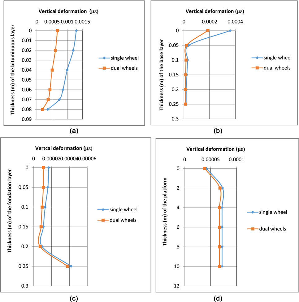
Figure 7. Effect of twinning in comparison with single wheel at level: (a) bituminous layer, (b) base layer, (c) foundation layer and (d) platform.
those obtained at the center of a single wheel. At the level of the bituminous layer, the difference between the deformations caused by the type of loading is high. This difference decreases as we get closer to the platform. The configuration of the load participates in the transmission of the load at the level of the roadway. The dual wheels reduce the transmission of the load at the level of the road where a reduction of the deformation.
These results are in agreement with those of [4]. The deformations obtained under a single-wheel load are much greater than the deformations obtained under a dual wheel load [4].
4. Conclusion
The purpose of this study was to determine the effect of dual wheels on lateritic pavements to understand the variation in the state of stress and deformation during the passage of traffic loads. The analysis of the results obtained made it possible to determine the distribution of the vertical contact stress on the circular impression of a single wheel and on the two discs of dual wheels, the pairing of which is described with the aid of two discs 0.125 m of radius, spacing 0.375 m. The study of this distribution allowed evaluating the maximum vertical deformation for each case of loading. This deformation is maximum in the center of the circular imprint where the vertical stress is maximum. Therefore, the vertical contact stress is non-uniform on the circular footprint and has a significant influence on the deformation of the pavement at the level of the bituminous layer. This non-uniformity has been shown by [9] under a tire thanks to the VRSPTA system according to the intensity of the load and the inflation pressure. In addition, the configuration of the load participates in the transmission of the load at the level of the roadway. The dual wheels reduce the transmission of the load at the level of the road hence a reduction of the deformation. It would be interesting to use other loading geometries (square or rectangular) to evaluate the effect of twinning wheel.
Cite this paper
Thiam, B.B., Samb, F. and Dione, A. (2018) Taking into Account the Effect of Dual Wheels on the Behavior of Lateritic Gravelly Pavements. Geomaterials, 8, 27-37. https://doi.org/10.4236/gm.2018.83003
References
- 1. Park, D.-W., Martin, A. and Masad, E. (2005) Effects of the Non Uniform Tire Contact Stresses on Pavement Responses. Journal of Transportation Engineering, 131, 873-879. https://doi.org/10.1061/(ASCE)0733-947X(2005)131:11(873)
- 2. Huang, Y. (1993) Pavement Analysis and Design. Prentice-Hall, Inc., Englewood Cliffs, New Jersey.
- 3. Stolarski, H. (1999) Load Testing of Instrument Pavement Section. Department of Civil Engineering, University of Minnesota, Minneapolis.
- 4. Sebaaly and Tabatabee (1989) Models for Damage Growth and Fracture in Nonlinear Viscoelastic Particulate Composites. Applied Mechanics Reviews, 57, 269-275.
- 5. Hirshhoron, R. (2003) The Estimation of Road Wear and Capital Costs, Canada. http://www.tc.gc.ca/pol/en/Report/FullCostInvestigation/Road/Road001.pdf
- 6. Perret, J. and Dumont, A.G. (2004) Modélisation des charges de l’essieu. Rapport final parti 1, Mandat de recherche ASTRA 2000/421.
- 7. Kim Y.R. (2010) Impact of Truck Loading on Design and Analysis of Asphaltic Pavement Structures. Department of Civil Engineering, University of Nebraska, Lincoln.
- 8. Yap, P. (1989) Truck Tire Types and Road Contact Pressures. Second International Symposium on Heavy Vehicle Weights and Dime.
- 9. De Beer, M., Fisher, C. and Fritz, J.J. (1997) Determination of Pneumatic Tire/Pavement Interface Contact Stresses Under Moving Loads and Some Effects on Pavements with Thin Asphalt Surfacing Layers. Eight International Conference on Asphalt Pavements, Seattle, Washington DC, 10-14 August 1997, 179-227.
- 10. Blad, R. (1999) Introducing Improved Loading Assumptions into Analytical Pavement Model Based on Measured Contact Stresses of the Tire. Paper Number CS5-3 Submitted to the International Conference on Accelerated Pavement Testing.
- 11. Huang, B., Mohamad, L. and Wathugala, W. (2002) Development of the Thermo-Viscoplastic Constitutive Model for HMA Mixtures. Presented at the Association of Asphalt Meeting (CD ROM), Colorado Springs, Paving Technologists 77th Annual.
- 12. Fang, H., Haddock, J., White, T. and Hand, A. (2004) On the Characterization of Flexible Pavement Rutting Using Creeps Model-Based Finite Element Analysis. Journal of Finite Element in Analysis and Design, 41, 49-73. https://doi.org/10.1016/j.finel.2004.03.002
- 13. Kim, D., Salgodo, R. and Altschaeffl, A. (2005) Effects of Super Single Tire Loading on Pavement. Journal of Transportation Engineering, 131, 732-742. https://doi.org/10.1061/(ASCE)0733-947X(2005)131:10(732)
- 14. Samb, F. (2014) Modélisation par éléments finis des chaussées en graveleux latéritiques traités ou non et application au dimensionnement mécanistique-empirique. Thèse de Doctorat Université de Thiès, Science de l’ingénieur.
- 15. Diakhaté, M. (2007) Fatigue et comportement des couches d’accrochage dans les structures de chaussée. Thèse de doctorat Génie civil, Université de Limoges.
- 16. Dione, A. (2015) Estimation du module réversible des Graves non traités et modélisation par éléments finis des chaussées souples en vue d’un dimensionnement Mécanistique-Empirique. Thèse de doctorat Géotechnique routière, Université de Thiès, Sciences de l’ingénieur.