World Journal of Nuclear Science and Technology
Vol.3 No.4(2013), Article ID:37591,8 pages DOI:10.4236/wjnst.2013.34019
A Flexible Multichannel Digital Random Pulse Generator Based on FPGA
1Physics Department, Amir-Kabir University of Technology, Tehran, Iran
2Radiation Application Research School, Nuclear Science & Technology Research Institute (NSRTI), Atomic Energy Organization of Iran (AEOI), Tehran, Iran
3Department of Energy Engineering, Sharif University of Technology, Tehran, Iran
Email: *hkhalafi@aeoi.org.ir
Copyright © 2013 Mohammad Arkani et al. This is an open access article distributed under the Creative Commons Attribution License, which permits unrestricted use, distribution, and reproduction in any medium, provided the original work is properly cited.
Received June 19, 2013; revised July 21, 2013; accepted August 9, 2013
Keywords: Field Programmable Gate Array (FPGA); Random Pulse Generator; Probability Distribution Function
ABSTRACT
The present paper describes a multichannel digital random pulse generator implemented in a 65-nm FPGA device. The random time interval generation is based on inverse transformation method. The output pulse generation rate, pulse width and the probability distribution function (PDF) of each channel might be individually selected by the computer through a USB cable connection. Statistical properties of the output channels can be adjusted and recorded in a fully dynamic flexible manner. The Poisson and uniform PDFs were tested and implemented for up to eight different channels in experiment, however, the implementation of any arbitrary PDF is possible by programming capability of the device as well. Detailed experimental results are expressed in the manuscript. The proposed equipment makes it possible to verify the complicated multichannel detection systems without having the radioactive experimental tests. This is a low cost instrumentation due to the FPGA-based construction.
1. Introduction
Nuclear particle detection is a stochastic process. Having a random pulse generator with a known PDF is an essential tool for a range of experimental laboratory tests and verifications of nuclear instrumentation modules (NIMs) [1-6]. A good example of a random pulse generator is the work done by Ponikvar [7] for testing and calibrating of dead time correction algorithms in spectroscopy systems. It is a digital random pulse generator with TTL compatible based on Pseudo Random Bit Sequence (PRBS) technique. The rate of pulse generation can be set to different values from 2.5 kP/s to 100 kP/s. That is controllable in steps of 2.5 kP/s. The minimum achievable time interval between two successive random pulses is 97.6 ns. All pulses have a fixed duration equal to 49 ns. The instrument suffers from the limited capability of output parameters adjusting. Abdel-Aal [8] has proposed a random pulse generator with a greater flexibility in selecting the desired statistical properties of the output pulses by software control basis. Ferrucci [9] has developed a FPGAbased random pulse generator for emulation of neutron detectors. The developed random pulse generator is based on Bernoulli trials ranging from 0.5 P/s to 1 MP/s. Neutron detection systems of nuclear reactors might be emulated in start-up and shutdown regimes by the mentioned equipment. This equipment can help the maintenance team to check and verify the electronic circuitry of the detection systems of nuclear reactors in a safe and reliable condition.
Analogue random pulse generators are also developed as reported in the literature [10-12]. In analogue designs, features of the output pulses are controlled via an analogue parameter like resistor or voltage of the circuitry. Therefore, the generator shall be facilitated with an appropriate measuring device to indicate the statistical parameters of the generated pulses. One of the advantages of digital implementation is the possibility of setting the output parameters accurately. This feature was well-defined in the present work as a built-in function of the innovative design to adjust different parameters of the output channels.
Software programming is another alternative for random pulse generation. Although it is the simplest method, it suffers from two major drawbacks: weak accuracy in timing characteristics of the output pulses and the limited output pulse generation rate (no more than several thousand pulses per second is possible). Therefore, hardware implementation is preferred at the expense of practical complications for accurate tests. Anyhow, software programming is preferred while the hardware implementation of an arbitrary function is not possible.
The current paper presents an investigation about the digital hardware implementation of an arbitrary random pulse generator by the aid of HDL programming and FPGA technology. The method is potentially capable to be applied to any arbitrary analytical PDF since the analytical functions are solved.
Random Time Interval Generation Based on Inverse Transformation Method
In this part, related theory for generation of uniform and Poisson random time intervals based on inverse transformation method is presented. Firstly, this is defined for Poisson PDF. Then in a similar way, the results for uniform PDF are described as well.
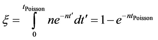
The probability of adjacent random events in Poisson PDF is a well-known relation [13,14]. By integration of the PDF in the limits of time interval of two successive events, the result would be the probability of the next event. Equating the integration result (CDF) to the normalized random number  results in Equation (1):
 (1)
(1)
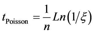
The time interval might be expressed by rearrangement of Equation (1) as:
 (2)
(2)
where tPoisson is the time interval of the next event with Poisson PDF. Time is assumed as a discrete parameter by a reference clock in digital circuits. Therefore, the time interval between pulses is counted by the number of digitization periods:
 (3)
(3)

Similarly, for a uniform PDF, the uniform time interval variable11 and the corresponding number of digitization periods can be expressed as Equations (4) and (5):
 (4)
(4)
 (5)
(5)


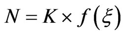
Generally, number of digitization periods between two successive random events can be written as Equation (6):
 (6)
(6)
K is a constant which depends on the digitization period and the average pulse generation rate. While, 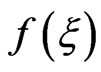 is a maths function which operates on
 . This is the basic idea behind the proposed method. Solution of random time interval needs arithmetic operations. Using FPGA technology, the hardware-based arithmetic operations are possible.
2. Methods and Results
Figure 1 shows the schematic diagram of the multichannel random pulse generator. A 32-bit integer pseudorandom number generator2 is used to generate uniform random numbers. Then, they are converted to 32-bit IEEE floating point format [15]. The random numbers are normalized between [0, 1] interval to generate the number of digitization periods with selected PDF by the block labelled as “Arithmetic IP cores”. This block performs the arithmetic floating-point operations (Equations (3) and (5)) using the dedicated hardware for high speed and accurate random time interval generation. A comprehensive explanation about the arithmetic operations is given in the next section. FIFO memory is necessary as a temporary memory buffer for data saving because of stochastic principal of pulse generation. The generated random time interval stored in FIFO memory buffer is fetched by a written VHDL code to generate the output pulses. Related hardware and timing of the system are synchronized with the clock provided by the PLL. Average output pulse generation rate, pulse width, and PDF of each channel are adjusted by the Nios II processing core [16] through USB cable connection to the computer and its interconnections to different parts of the design. Figure 1 shows more information in details. The maximum working frequency is practically determined. It depends on the complexity of the architecture and the speed characteristics of the device. Detailed experimental features of the architecture are reflected in Table 1 for one-channel and
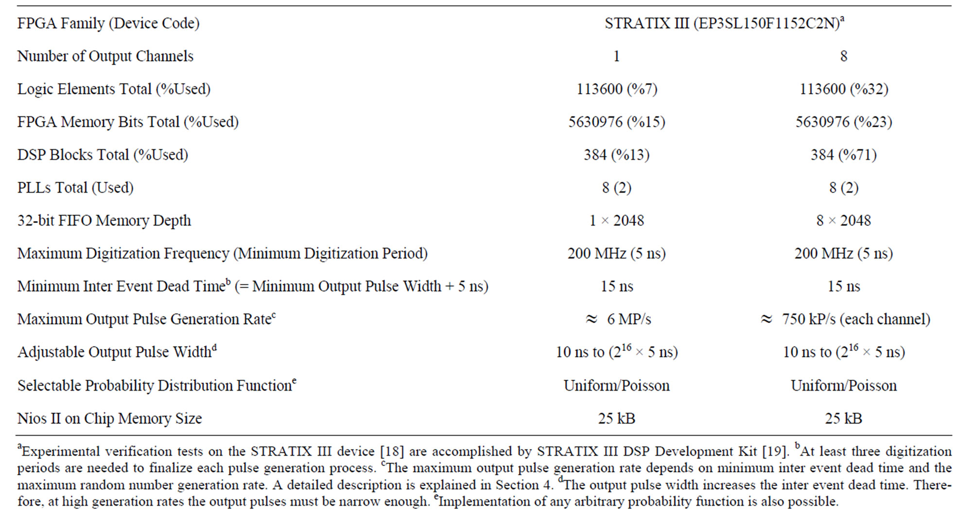
Table 1. Experimental test results comparing the amount of provided hardware resources and the maximum possible performance for different number of output channels.
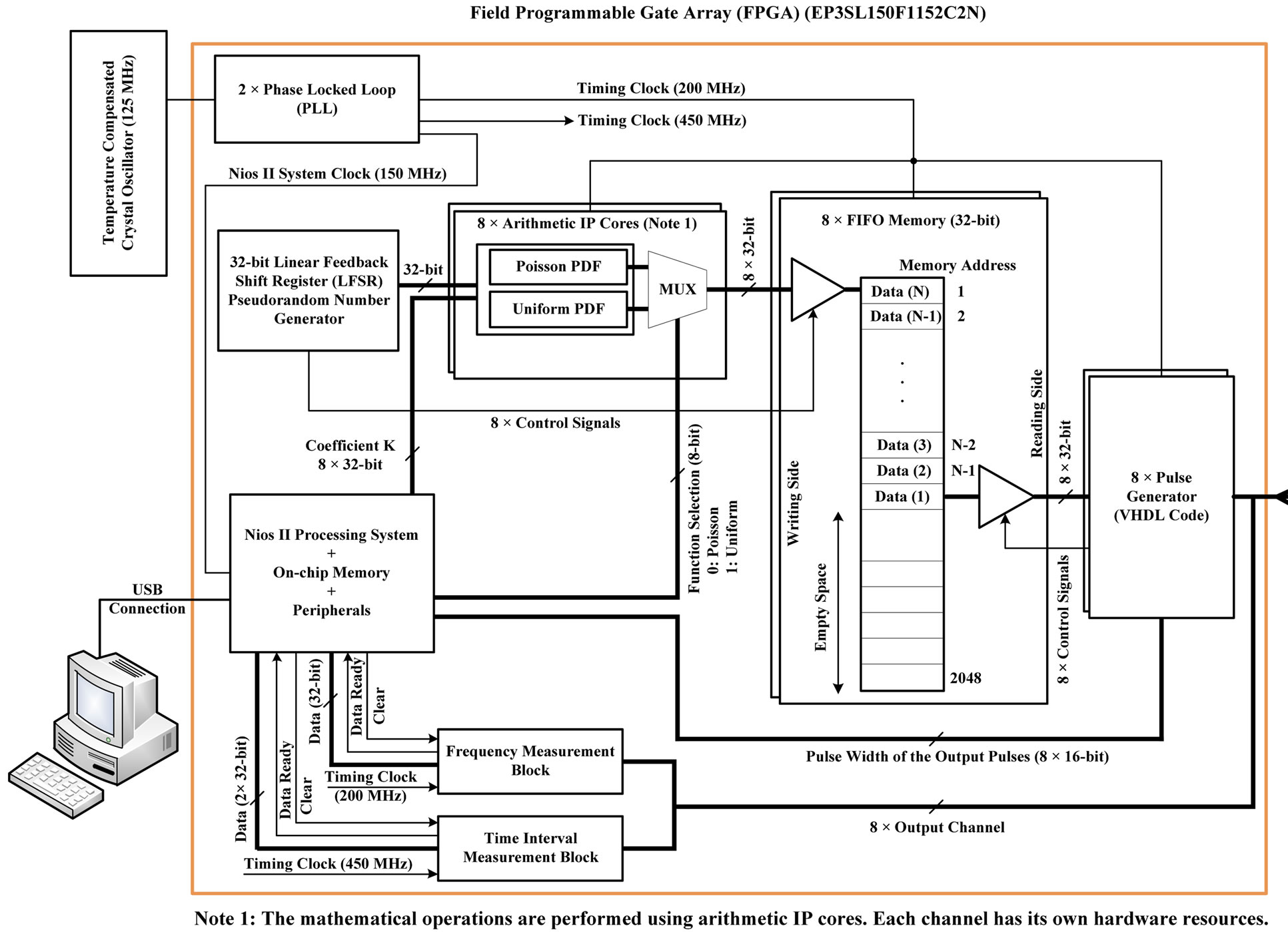
Figure 1. Schematic diagram of the eight-channel digital random pulse generator.
eight-channel structures.
Figure 2 shows the captured information of the random pulses by a typical laboratory digital oscilloscope. In Figure 2, random pulses generated by channels 1 and 2 are demonstrated. These channels have different PDFs with the same selected pulse generation rate. More explanation about the results will be given shortly in next sections.
2.1. Use of IP Cores in Hardware-Based Arithmetic Operations
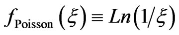
Wide varieties of configurable IP cores of different sizes and complexities optimized for FPGAs have been provided. Therefore, performing the arithmetic operations by HDL programming is readily possible [17]. Figure 3 shows the method of hardware based implementation of arithmetic operations for Poisson random time interval generation. The random number generated by LFSR and the coefficient KPoisson determined by the NIOS II processing core are integer inputs of the blocks. They are converted to floating point numbers to be operated by the next arithmetic operations.
The floating point random number is normalized and inverted to generate the fPoisson(ξ) by the Natural Logarithm Block. Finally, NPoisson is calculated and the result is converted to integer format to be stored by FIFO memory buffer. The calculation time using a typical FPGA is around 100 ns. The method of hardware implementation accelerates the speed of pulse generation significantly. The PDF of output pulses is also perfect since analytical solution is employed.
2.2. Experimental Tests and Verifications
Each output channel generates a train of pseudorandom pulses. Therefore, the statistical features of the pulses shall be examined properly. The followings are major tests performed on the system.
2.2.1. The PDF of Output Pulses
In order to assure the proper functioning of the generator,
Figure 2. Output random pulses generated by eight-channel architecture. Channel one (top) and channel two (bottom) show random pulses with Poisson and uniform PDFs, respectively (Captured by a typical laboratory digital oscilloscope).
the output PDFs of the output pulses are analysed by utilizing the time interval measuring capability implemented in the design. The “Time Interval Measurement Block” (shown in Figure 1) functions as a utility for PDF measurement. The time resolution and inter event dead time are 2.22 ns and 6.67 ns respectively. Up to 500 kP/s can be analysed by the block continuously. Both uniform and Poisson output random pulses are analysed and the results are illustrated in Figures 4 to 7. Figures 4 and 5 show the recorded time intervals of 104 output pulses with uniform and Poisson PDFs respectively. As it is clearly seen, for Poisson PDF pulses with short intervals are more probable. Figures 6 and 7 are better indications for analysis of the output PDFs. At output mean generation rate of 500 kP/s, 2 × 10⁵ pulses are analysed and the resultant PDFs are shown.
2.2.2. The Effect of Dead Time on Mean Generation Rate
During the time that the generator is involved in the previous random pulse generation (= three digitization periods), no output pulse generation can take place if the next event falls in this period. The dead time is equal to
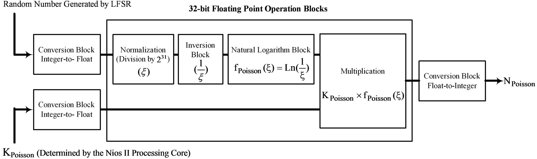
Figure 3. Hardware based implementation of arithmetic operations for Poisson time interval random variable calculator.
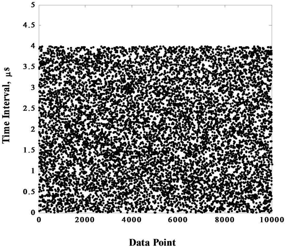
Figure 4. Time interval of the output pulses with uniform PDF (GRset = 500 kP/s, N.S. = 104).
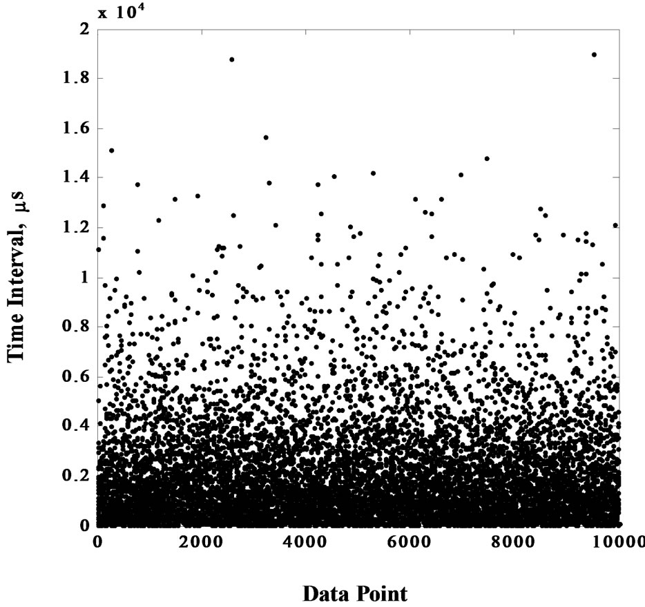
Figure 5. Time interval of the output pulses with Poisson PDF (GRset = 500 kP/s, N.S. = 104).
15 ns (3 × T) as it is mentioned in Table 1. At high generation rates, this effect is more probable. Therefore, mean generation rate is shifted to the lower values due to the loss of short interval pulses. Table 2 shows the detailed information of the output mean generation rate of the system at different values of GRset. The maximum deviation is expected at 7 MP/s. This is greater for Poisson PDF as pulses with short intervals are more probable. The error is approximately eight per cent. Note that these data are averaged over 2.5 × 10³ measurements performed on the output pulses.
A comprehensive comparison of uniform and Poisson pulse generation rate against different values of GRset is illustrated in Figure 8. Greater losses is seen by the
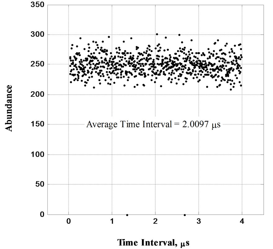
Figure 6. Histogram of the time intervals of the output pulses with uniform PDF (GRset = 500 kP/s, N.S. = 2 × 10⁵, 800 bins).
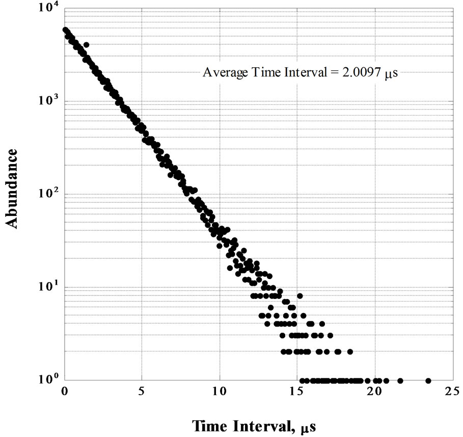
Figure 7. Histogram of the time intervals of the output pulses with Poisson PDF (GRset = 500 kP/s, N.S. = 2 × 10⁵, 400 bins).
curve of Poisson PDF. This figure shows important information about the practical rate range of output pulse generation. Above the 6 MP/s, the curves are distorted due to the maximum random number generation rate. Therefore, the maximum pulse generation rate with an error less than 5 per cent is limited to 6 MP/s. The measurements are performed by the capability of output frequency measurement block shown in Figure 1. As pulses are lost due to the inter event dead time, GRExp is lower than GRset generally.
2.2.3. Stability Check of Mean Generation Rate
The output mean generation rate is measured every sec-
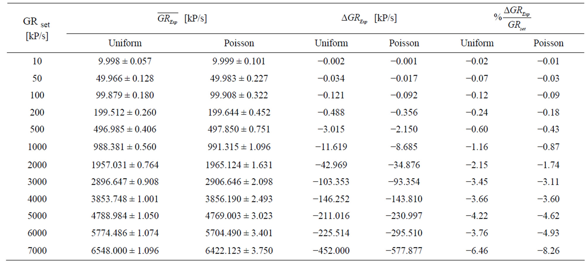
Table 2. Statistical properties of the random pulse generator at different pulse generation rates. The data is computed over 2.5 × 10³ measuring samples of the parameters.
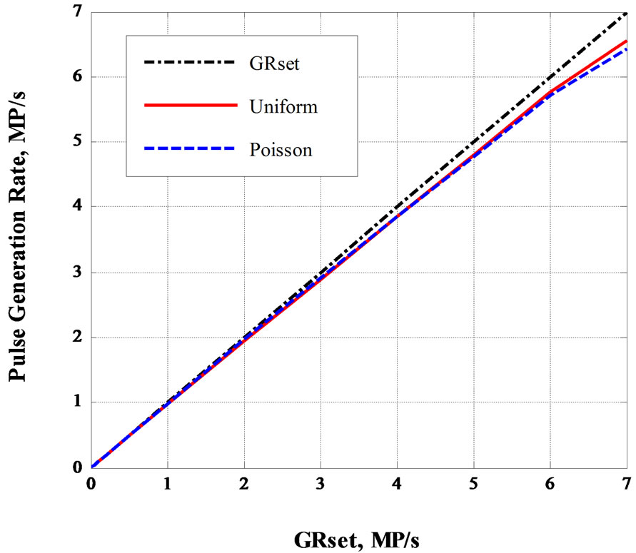
Figure 8. Dead time effects on output pulse generation rate at different values of GRset.
ond. The histograms of the results are plotted in Figures 9 and 10 for the two different PDFs. Data is scattered in a Gaussian shape. Statistical properties of the results are mentioned by the figures. No shift in output mean generation rate is seen during the data collection time interval. A good stability for timing features is expected as the basis for the time discretization is a temperature compensated crystal oscillator. This is one of the advantages of digital technology.
3. Discussion
A description of the proposed method and its experimental results were given in previous sections. In this part, a general discussion about the results is initiated. Table 1
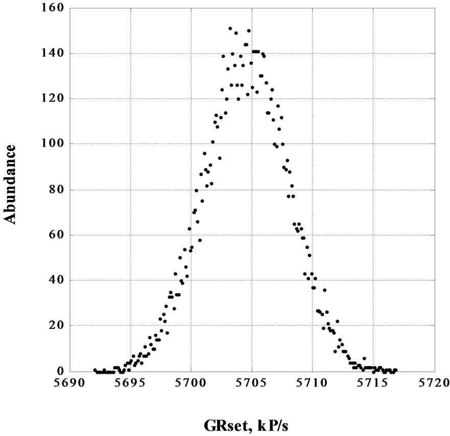
Figure 9. Histogram of the output pulse generation rate with Poisson PDF (GRset = 6 MP/s, GRExp = 5.704488 MP/s, STD = 3.456 kP/s, N.S. = 104, 200 bins).
shows a summary of the provided resources and the practicable performance by the device based on the structures. The maximum digitization frequency determines the maximum output pulse generation rate. The maximum digitization frequency is measured equal to 200 MHz for the structures based on the FPGA device used for the test and the implementation. The timing features of the system are given in Table 1 in details.
Each output pulse generation needs three clock pulses (setting, resetting, and finalizing of the process). That is why the minimum inter event dead time was reported as 15 ns with minimum pulse width of 10 ns.

Figure 10. Histogram of the output pulse generation rate with uniform PDF (GRset = 6 MP/s, GRExp = 5.774492 MP/s, STD = 1.056 kP/s, N.S. = 104, 200 bins).
IP cores have clock latencies. Therefore, calculation process performed by the hardware generates random time intervals every 30-digitization period. The maximum random time interval generation rate is limited to the values, which are smaller than 7 million samples per second. As the inter event dead time is a source of error, the maximum possible output pulse generation rate with an error less than 5 per cent was measured equal to 6 MP/s for one channel architecture. Since there is a single random number generator in the design, while there are eight output channels, random pulse generation rate cannot exceed more than 750 kP/s for each channel. This is the only possible limitation imposed by multichannel implementation.
FPGAs support multiple digital voltage standards. The output pulses shown in Figure 2 are either 2.5-V LVTTL or 1.2-V LVTTL standards depending on the chosen IO pin of the device. This is an advantage, which makes the design easily compatible with different digital voltage standards. Another important capability of FPGAs is the possibility of upgrading and revising of the design based on programming. The unique features of the technology make the system as a cost-effective tool for future indepth research into the certification of multichannel stochastic detection systems by non-radioactive experiments.
4. Conclusion
Random pulse generator is one of important apparatuses in nuclear experiments. A range of equipment with different features has been invented previously. An efficient multichannel random pulse generator, which is low cost due to implementation on a single FPGA device, was presented. The simple architecture can be easily modified to be compatible with any especial experimental case study. Uniform and Poisson PDFs were tested in experiment. Average output pulse generation, output pulse width, and PDF of each channel can be adjusted by the computer through USB cable connection. Detailed useful experimental test results were shown in Table 1. The time resolution is 5 ns, minimum pulse width is 10 ns, and the minimum inter event dead time is 15 ns for the design.
The maximum tested in experiment output pulse generation rate is 6 MP/s with a relative error less than 5 percent. This error is due to the dead time effects of the equipment. As the generator is capable of generating pulses with different statistical characteristics, this is a useful flexible instrument to handle the complex experimental tests on nuclear detection systems especially for those are multichannel types. The core of the random pulse generator is the random number generator. This is performed by LFSR (a pseudorandom number generator) technique which is the only source of random number generation for all output channels. Useful scientific papers have been published on random number generators based on FPGAs. The architecture can be facilitated with modern techniques to be more efficient. Multiple random number generators in the design can make the output pulse generation speedier for multichannel structure as well. Future experimental tests on nuclear detection systems can gain useful knowledge of the design to become more proficient as much as FPGA technology allows.
REFERENCES
- M. Wiernik, “Normal and Random Pulse Generators for the Correction of Dead-Time Losses in Nuclear Spectrometry,” Nuclear Instruments and Methods, Vol. 96, No. 2, 1971, pp. 325-329. http://dx.doi.org/10.1016/0029-554X(71)90324-7
- J. J. Gostely and P. Lerch, “Counting Signals from Radioactivity-Measurement Systems,” Nuclear Instruments and Methods in Physics Research Section A: Accelerators, Spectrometers, Detectors and Associated Equipment, Vol. 290, No. 2-3, 1990, pp. 521-528. http://dx.doi.org/10.1016/0168-9002(90)90572-N
- J. Gál, B. György and J. Pálvölgyi, “A Random Tail Pulse Generator for Simulation of Nuclear Radiation Detector Signals,” Nuclear Instruments and Methods, Vol. 171, No. 2, 1980, pp. 401-406.
- P. C. Johns and M. J. Yaffe, “Correction of Pulse-Height Spectra for Peak Pileup Effects Using Periodic and Random Pulse Generators,” Nuclear Instruments and Methods in Physics Research Section A: Accelerators, Spectrometers, Detectors and Associated Equipment, Vol. 255, No. 3, 1987, pp. 559-581. http://dx.doi.org/10.1016/0168-9002(87)91227-7
- R. E. Abdel-Aal, “A Programmable Gaussian Random Pulse Generator for Automated Performance Measurements,” Nuclear Instruments and Methods in Physics Research Section A: Accelerators, Spectrometers, Detectors and Associated Equipment, Vol. 276, No. 3, 1989, pp. 573-576. http://dx.doi.org/10.1016/0168-9002(89)90585-8
- P. Dajing, “A Uniform Amplitude Spectrum Generator for Test of the Maximum Effective Pulse Rate of MCAs,” Nuclear Instruments and Methods in Physics Research Section A: Accelerators, Spectrometers, Detectors and Associated Equipment, Vol. 251, No. 3, 1986, pp. 531- 535. http://dx.doi.org/10.1016/0168-9002(86)90648-0
- D. Ponikvar, “Generator of Pseudo Random Pulses,” Nuclear Instruments and Methods in Physics Research Section B: Beam Interactions with Materials and Atoms, Vol. 83, No. 1-2, 1993, pp. 295-299. http://dx.doi.org/10.1016/0168-583X(93)95941-W
- R. E. Abdel-Aal, “A Versatile Programmable CAMAC Random Pulse Generator,” Nuclear Instruments and Methods in Physics Research Section A: Accelerators, Spectrometers, Detectors and Associated Equipment, Vol. 309, No. 1-2, 1991, pp. 331-338.
- F. N. Ferrucci, C. A. Verrastro, G. E. Ríos and D. Estryk, “FPGA-Based Random Pulse Generator for Emulation of a Neutron Detector System in a Nuclear Reactor,” IEEE VII Southern Conference on Programmable Logic (SPL), Cordoba, 2011, pp. 103-108. http://dx.doi.org/10.1109/SPL.2011.5782633
- J. Lauch and H. U. Nachbar, “Random Pulse Generator with a Uniformly Distributed Amplitude Spectrum,” Nuclear Instruments and Methods in Physics Research Section A: Accelerators, Spectrometers, Detectors and Associated Equipment, Vol. 267, No. 1, 1988, pp. 177-182. http://dx.doi.org/10.1016/0168-9002(88)90645-6
- W. B. Divon and B. Rozen, “A Random Pulse Generator,” Nuclear Instruments and Methods, Vol. 39, No. 1, 1966, pp. 77-87. http://dx.doi.org/10.1016/0029-554X(66)90046-2
- G. White, “The Generation of Random-Time Pulses at an Accurately Known Mean Rate and Having A Nearly Perfect Poisson Distribution,” Journal of Scientific Instruments, Vol. 41, No. 6, 1964, pp. 361-364. http://dx.doi.org/10.1088/0950-7671/41/6/302
- G. F. Knoll, “Radiation Detection and Measurement,” John Wiley & Sons, Inc., 1999.
- C. H. Vincent, “Random Pulse Trains Their Measurement and Statistical Properties,” Peter Peregrinus Ltd., 1973.
- IEEE 754, “Standard for Binary Floating-Point Arithmetic,” 1985.
- ALTERA Corporation, “Nios II Software Developer’s Handbook Version 11.1,” 2011. www.altera.com
- ALTERA Corporation, “QUARTUS II Handbook Version 11.1,” 2011. www.altera.com
- ALTERA Corporation, “STRATIX III Device Handbook,” 2011. www.altera.com
- ALTERA Corporation, “STRATIX III DSP Development Kit Reference Manual,” 2008. www.altera.com
Nomenclature
CDF: Cumulative distribution function.
FIFO: First-in, First-out.
FPGA: Field programmable gate array.
GRExp: Measured output mean generation rate.
GRset: Selected output mean generation rate.
IEEE: The institute of electrical and electronics engineers.
IP: Intellectual property.
n: Average number of random pulses per second.
NPoisson: Number of digitization periods between two successive random pulses with Poisson PDF (an integer number).
N.S.: Number of samples.
NUniform: Number of digitization periods between two successive random pulses with uniform PDF (an integer number).
PDF: Probability distribution function.
PLL: Phase locked loop.
P/s: Pulse per second.
STD : Standard deviation.
t: Time variable.
tPoisson: Time interval between two successive random pulses with Poisson PDF.
tUmax: Maximum time interval between pulses with uniform PDF.
tUniform: Time interval between two successive random pulses with uniform PDF.
 Average time interval between pulses with uniform PDF.
T: Digitization period.
TTL: Transistor-transistor logic.
VHDL: Virtual hardware description language.
ζ: Normalized uniform random variable (0 ≤ ζ ≤ 1).
 : Output mean generation shift from
 .
.
NOTES
*Corresponding author.
1In uniform PDF: .
.
2Linear Feedback Shift Register (LFSR) technique is utilized. The absolute value of the random number is used as a uniform random number variable.