Journal of Encapsulation and Adsorption Sciences
Vol.2 No.3(2012), Article ID:23073,6 pages DOI:10.4236/jeas.2012.23004
Determination of the Optimal Speed of Pultrusion for Large-Sized Composite Rods
Department of Composite Materials, Moscow State Technological University “STANKIN”, Moscow, Russia
Email: al.krasnov@mail.ru, kazakov_iliya@mail.ru
Received June 18, 2012; revised July 20, 2012; accepted August 6, 2012
Keywords: Composite Material; Pultrusion; Stress-Strain State; Permeability; Oversized Rod
ABSTRACT
The paper describes a mathematical model of the stress-strain state of polymer composite materials in the pultrusion process of large-sized products. The influence of the pull speed on the stress-strain state of the products is investigated. To determine the maximum possible pull speed series of solutions at different pull speeds are obtained. Depending on the maximum strain in the cross section of the rod determined the optimal value of pulling speed.
1. Introduction
Pultrusion is one of the most common ways to manufacture large products made of polymer composites. The possibilities to improve the performance of pultruded products depending on the reinforcement scheme are well studied [1-4]. The influence of constructive and technological parameters of pultrusion process on the properties of the resulting products is no less important. The most important to choose the optimal speed at which the quality product without the main cracks and discontinuity is received. The known mathematical models considered pultrusion process in the assumption that the polymerization of the resin is completed to the exit products from the die [5,6]. This assumption reduces the productivity of the process, making it unprofitable. A complex numerical model for evaluating stress-strain state of polymer composite material is developed. This model assumes incomplete polymerization process within the die. The relation between pull speed and stress-strain state of composite product at the exit from the die is investigated. As an example the optimum value of the pull speed is determined.
2. Statement of the Problem
Figure 1 shows the process of passing the composite material through a heated die. At the same time the polymerization process takes place. If the pull speed is high enough (>60 mm/min), then polymerization process of the oversized product does not have time to finish before it exits from the die. At this, the strain occurred in a polymerized part of the rod may exceed the maximum allowable values for the material which leads to the main crack appearance. The thermal stresses, the pressure of the liquid resin and chemical shrinkage are effects on the value of strain.
3. Stress-Strain State Model
Consider the section A-A of the rod consisting of two regions (Figure 2(а)).
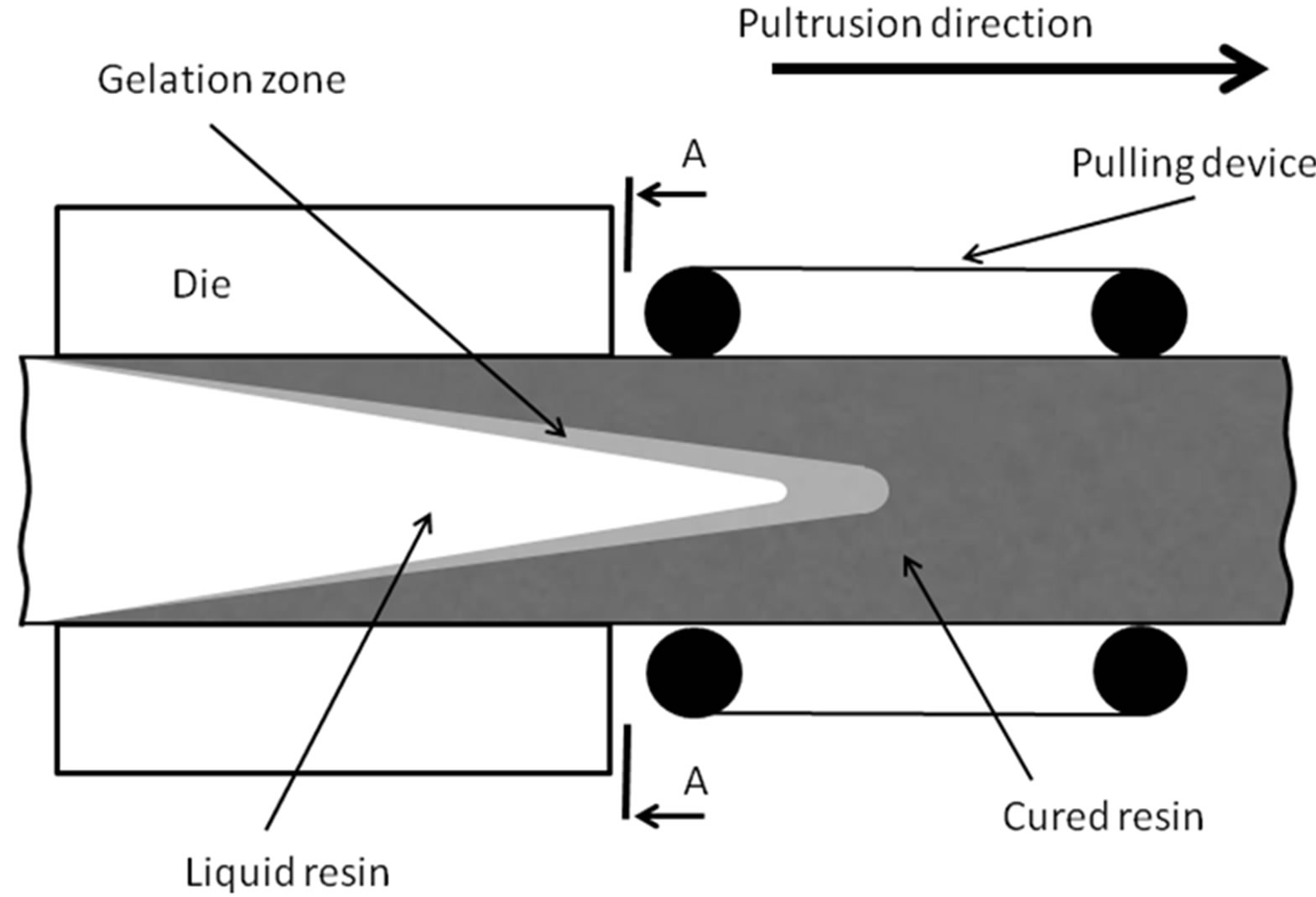
Figure 1. Scheme of pultrusion.
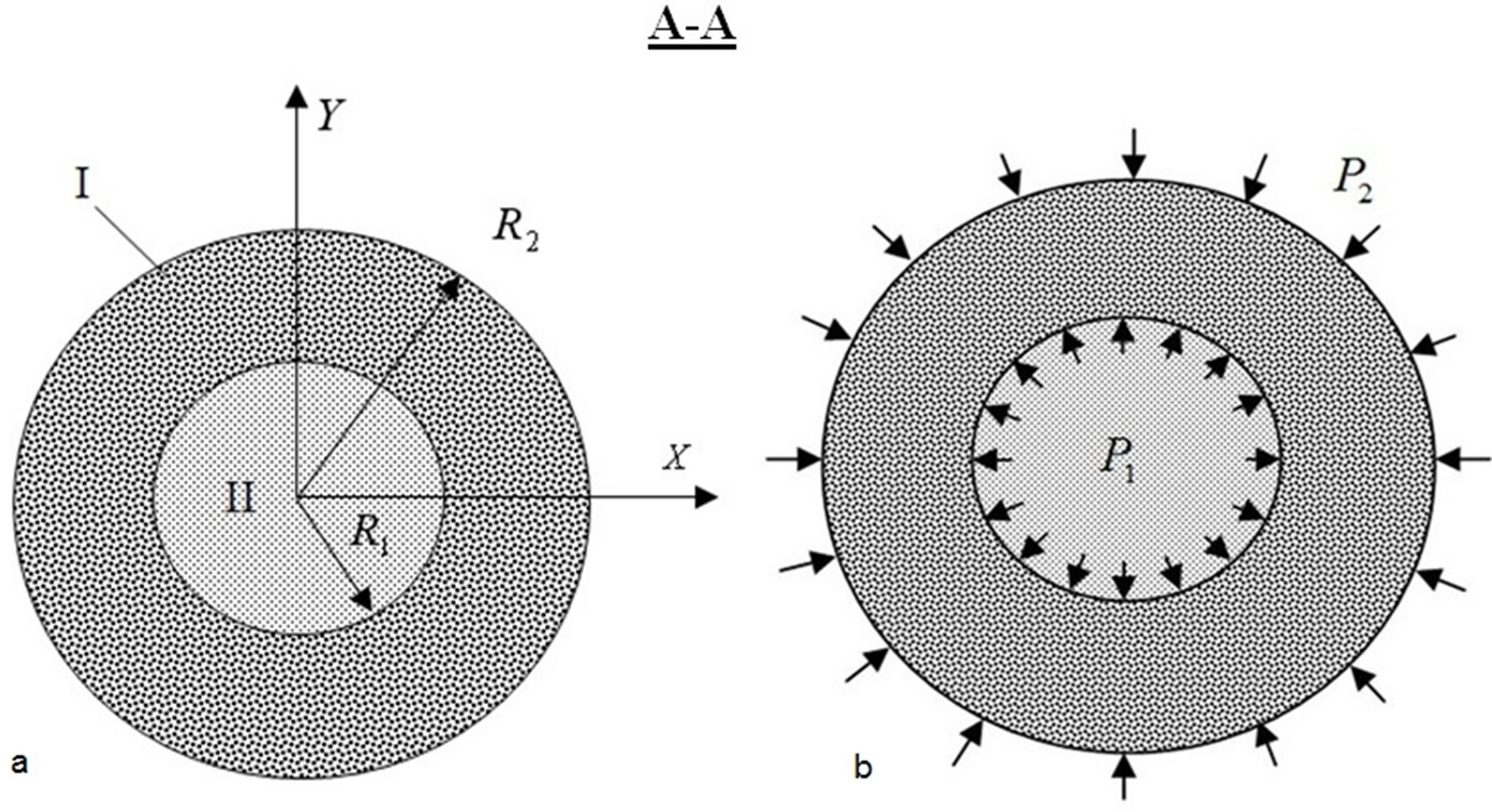
Figure 2. The rod cross-section (a) and the boundary conditions (b).
The outside Area I corresponds with cured zone. The inner Area II corresponds with zone where resin with filler is uncured.
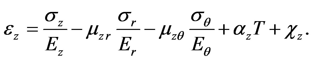
Hooke’s law for orthotropic solid in cylindrical coordinates taking into account the chemical shrinkage is given by
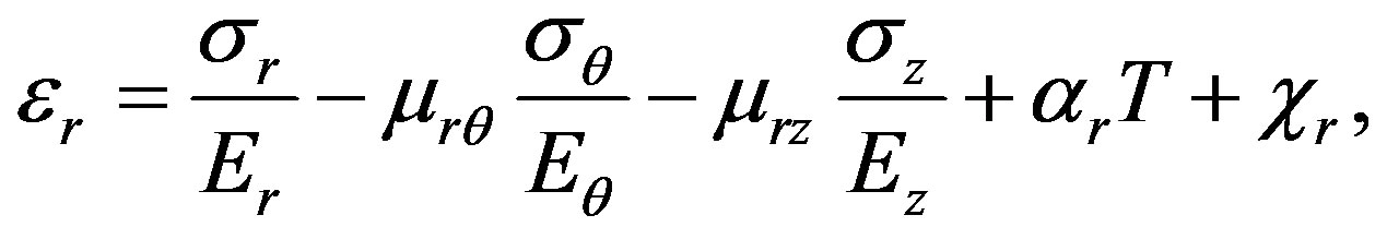 (1)
(1)
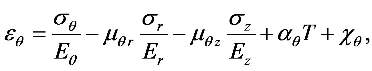 (2)
(2)
 (3)
(3)
where ,
,  and
and —radial, circumferential and axial stress components;
 ,
,  and
and —radial, circumferential and axial strain components;
 ,
,  and
and —modulus of elasticity of material in corresponding directions;
 ,
,  ,
,  ,
,  ,
,  and
and —Poisson’s ratios;
 ,
, ,
, —linear thermal expansion coefficients in corresponding directions;
 —temperature function;
 ,
, ,
, —chemical shrinkage of material in corresponding directions.
We considered the outside Area as transversely isotropic cylindrical solid. For this solid
 (4)
(4)
Chemical shrinkage of the material along the fibers is neglected, i.e. .
.
Also under symmetry of elastic constants the next relations are take place:
 . (5)
. (5)
For generalized plane strain state
 (6)
(6)
The equilibrium equation for infinitely small element inside cylinder in local cylindrical coordinates  (z direction—along fibers) for
  plane is follow:
 (7)
(7)
Geometrical relations
 (8)
(8)
It is accepted that inner Area II of the rod is acting like incompressible liquid. The liquid resin is pressurized and acts on the walls of cured cylinder (Figure 2(b)). Then boundary conditions for cylinder are following
 for
for 
 for
for  (9)
(9)
Solve Equations (1)-(3) by stresses, using (4)-(8) and boundary conditions (9) the following equations for stresses can be obtained:
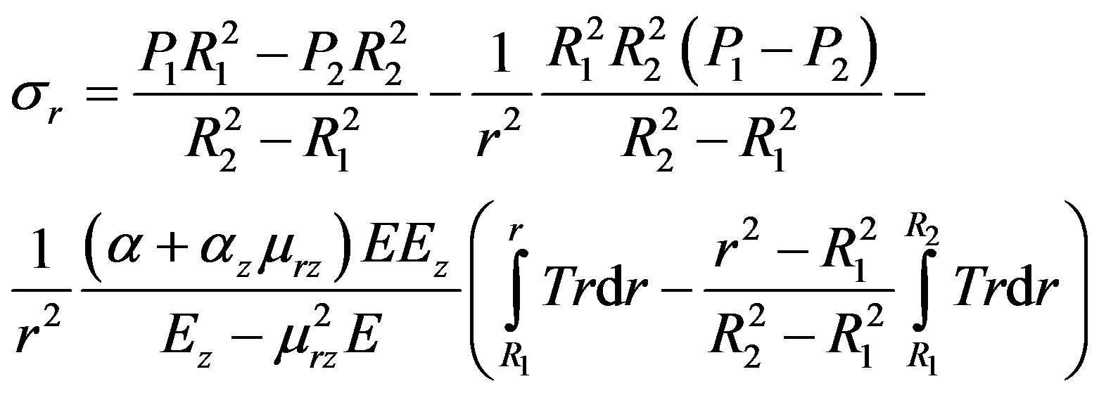 (10)
(10)
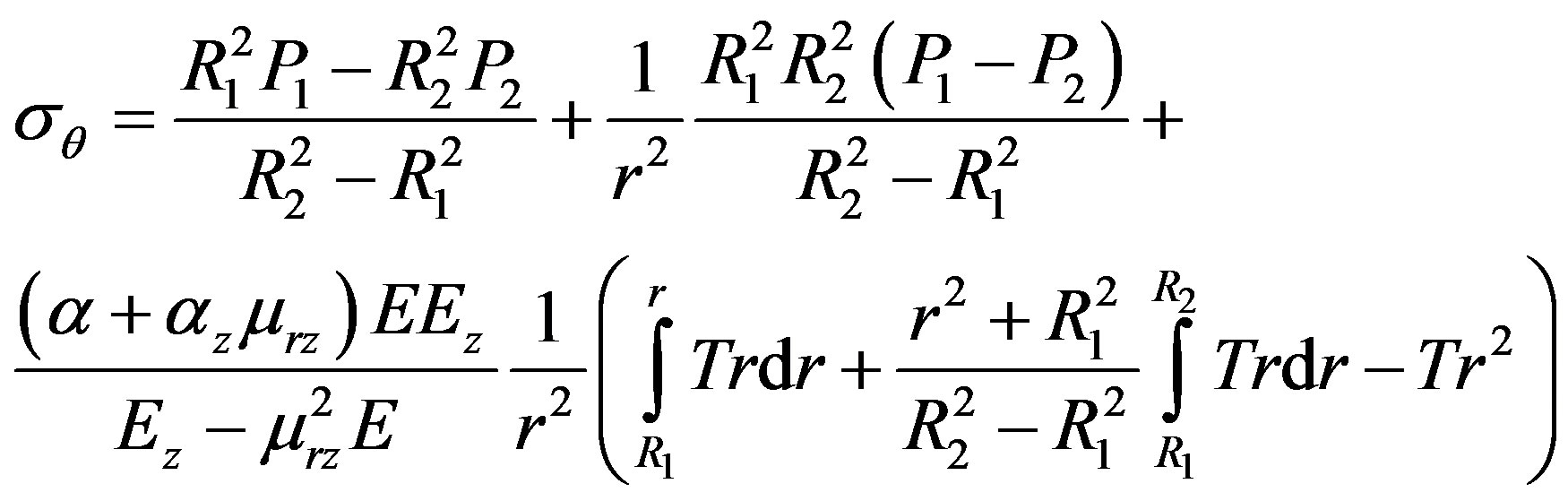 (11)
(11)
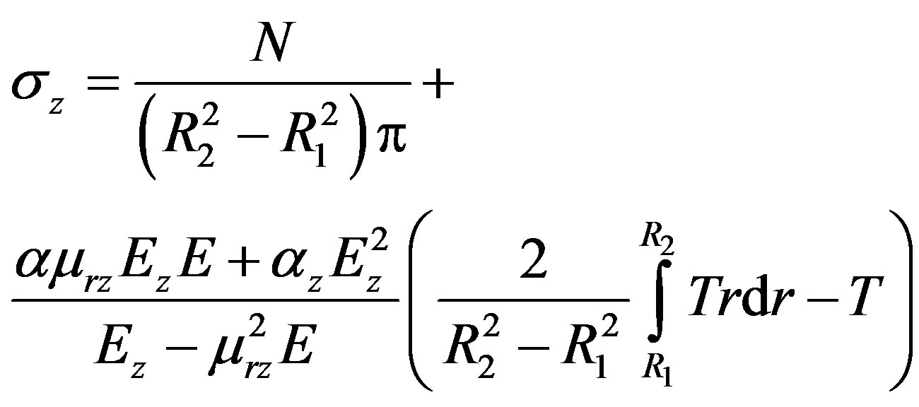 (12)
(12)
The value of pulling force N we can find from (13):
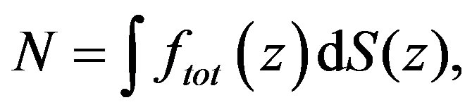 (13)
(13)
where  is the total resisting force per unit area of the composit in contact with the die and S the internal surface area of the die. The solution for (13) is described in [7].
4. Failure Criteria
As mentioned above, at high pull speeds the strain occurred in a polymerized part of the rod may exceed the maximum allowable values for the material which leads to the main crack appearance. As a strength criterion the maximum deformation criterion is chosen which has the form [8]:
 (14)
(14)
The study determined that the values of the stresses in the cross section of the rod are far from the limit values, whereas the strain exceeds the limiting values at high pull speed. Therefore, the maximum deformation criterion was chosen as the primary. The sign “+” means tension, “−” compression,  the ultimate strain obtain as
 (15)
(15)
there —experimentally determined limiting values of stresses for a material by transverse tension, transverse compression and tension along the fibers, respectively. The strains are defined by (1)-(3) with subject to (10)-(12) and compared with ultimate values from (15).
5. The Heat Transfer and Polymerization Model
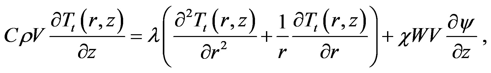
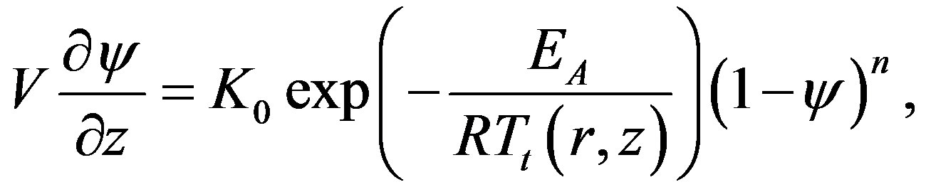
For stress-strain state determination we need to know the temperature field distribution and location of the border between cured and liquid material. For this we should solve the non-linear heat transfer and polymerization problem which for pultrusion of the rod has a view [9]:
 (16)
(16)
 (17)
(17)
 (18)
(18)
where C—heat capacity; ρ—density; V—pulling velocity; W—reaction heat; λ—thermal conductivity; ψ—degree of polymerization; χ—resin volume; Tt—absolute temperature; T0 —rod temperature at inlet of die; K0—preexponential factor; EA —active energy of process activation; R—gas constant; n—total reaction order by reacting components; γ—heat-transfer coefficient; —ambient temperature.
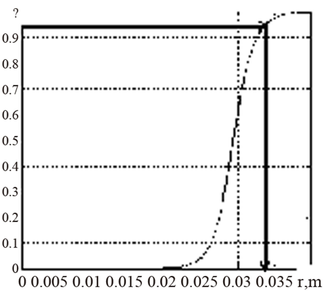
Based on the solution of (16)-(18) by the method of finite differences [11] the radius R1 of the inner zone II is obtained. For this radius the degree of polymerization ψ = 0.95 (Figure 3(a)).
Using the value R1 the interval of the temperature distribution over the cross section is determined for the calculation of integrals in the (10)-(12) (Figure 3(b)). The stress values are numerically obtained using the trapezium method.
6. Pressure Model
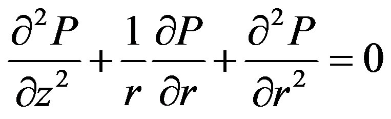
One of the process parameter in pultrusion is the pressure-rise inside a die. The pressure of liquid resin appears due to fiber/resin system passes through the die (Figure 4). The equation of incompressibility [5,6] for the flow of resin moving through the fibers in a cylindrical coordinate system is follow:
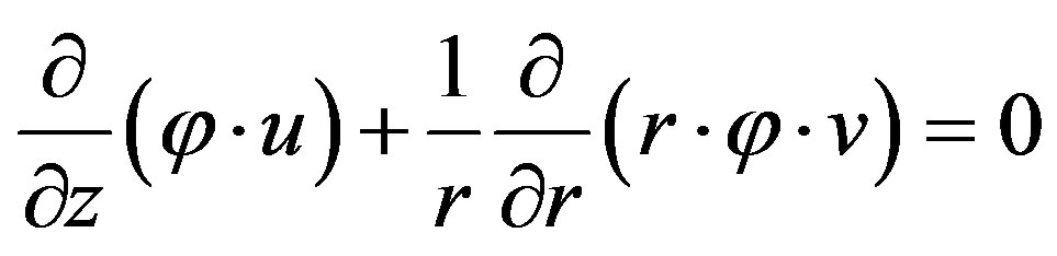 (19)
(19)
In the projections of the velocity vectors onto the axis z (along the rod axis)
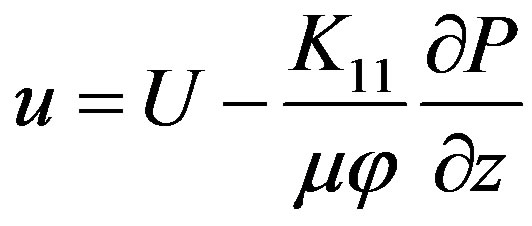 (20)
(20)
In the projections of the velocity vectors onto the axis r (in radial direction)
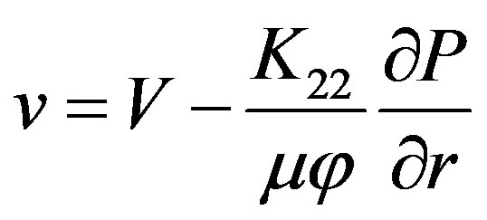 (21)
(21)
here K11—medium permeability in axial direction; K22— medium permeability in radial direction; v—component of resin velocity in radial direction; u—component of resin velocity in longitudinal direction; V—component of fiber velocity in radial direction; U—component of fiber velocity in longitudinal direction (pull speed); μ—viscosity;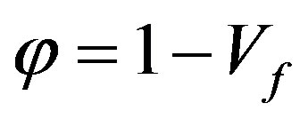 —porosity; Vf —the function of changes in the fiber volume fraction along the length of the tapered die.
 (a)
(a)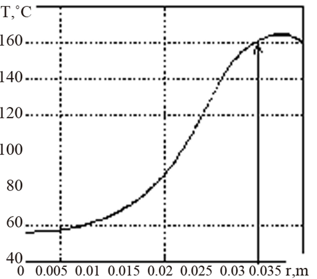 (b)
(b)
Figure 3. Defining the radius of the inner zone (a) and temperature interval (b).
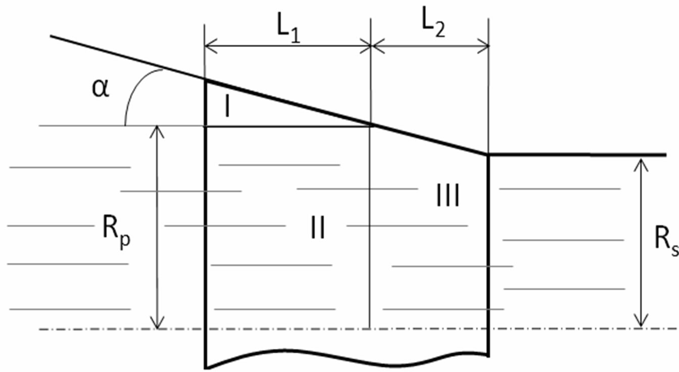
Figure 4. The input section of the die and its geometrical parameters.
Expressions (19)-(21) are based on Darcy’s law for the resin flow, passing through a porous medium (fiber) at low speeds. According to Gebart’s model [10] the permeability in the axial and transverse directions are given as
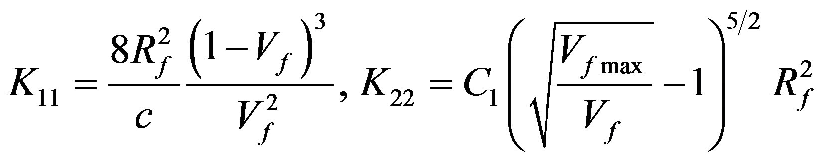 (22)
(22)
where Rf is the fiber radius, c = 53, C1 = 0.231 and Vfmax = 0.9068.
Taking into account (20) and (21) and that
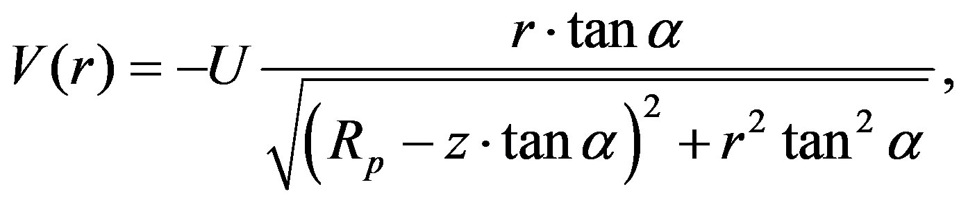
where —geometrical parameter of the input section of the die (the taper angle),
  is the local radius of the die wall, we can obtain the following differential equation for the pressure from (19):
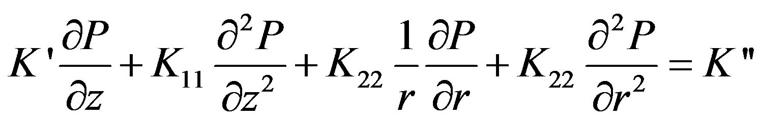 (23)
(23)
where
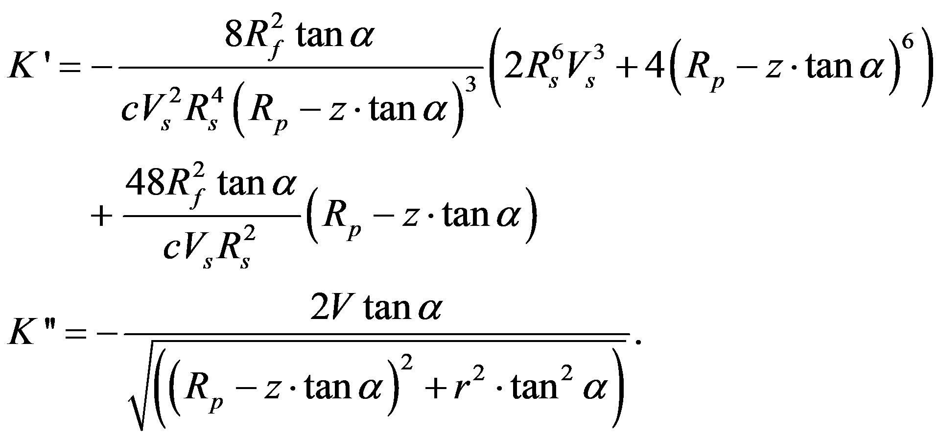
Vs—is the fiber volume fraction in the straight portion of the die (or finished products), Rp is the aperture radius of the last pre-form plate.
To solve the problem (23) by finite differences method [11], the solution region divided into four zones (Figure 4). In this only half die simulated due to symmetry. It was assumed that the zone I completely filled a resin (it is a resin backflow region there excess resin is squeezed out of the die due to the compression of the fiber/resin system). For this region Equation (23) has a view:
 (24)
(24)
For a region II 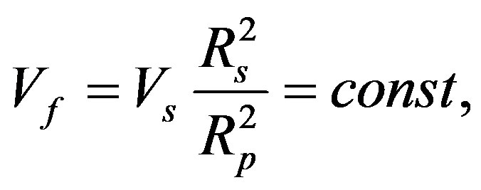 therefore (23) can be written as
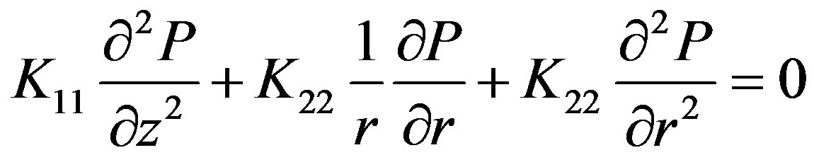 (25)
(25)
For a III region the Equation (23) is applied in general form. For a IV region the Equation (25) is used taking into account that 
At the computational domain inlet, the pressure is considered to be equal to atmospheric pressure P0 (101,325 Pa). The boundary conditions on the tapered wall of the die were determined from the ratio of velocity components at the boundary: . The boundary condition for the grid points of the rod, where the polymerization is completed (
 ):
): . At the center line (r = 0), and At the Top boundary (straight portion of die):
 .
.
7. Results and Discussion
Thus, solving the system of Equations (10)-(18), (23)-(25) we can obtain the strains for every rod cross section at the outlet of the die and, comparing them with ultimate values, prevent main crack appearance.
The following parameters were used when solving the problem. The rod radius Rs = 38 mm, pull speed 70 mm/min. Pre-form plate radius Rp = 1.085Rs. Fiber radius Rf = 0.013 mm, fiber volume fraction Vs = 0.6, taper angle α = 250, length of the taper part of the die L1 + L2 = 76 mm, the resin viscosity under normal conditions  Pa*s, P0 = 101325 Pa. The Poisson’s ratios
 ; The thermal expansion coefficients
  1/С0 ,
  1/С0 , Modulus of elasticity
  MPa,
MPa,  MPa. The next strength data for composit material are used [8]: longitudinal tensile strength
  MPa, transverse tensile strength
  MPa, transverse compressive strength
  MPa. Die temperature settings (the length of straight portion of the Die is 1 m): 110-150-190-160 С0. The parameters such as preexponential factor, reaction heat, active energy of process activation and total reaction order by reacting components was taken from [9].
As a result of solving the problem (23)-(25) the centerline pressure profile along the Die is obtained (Figure 5).
Figures 6 and 7 show the profiles of the radial (Figure
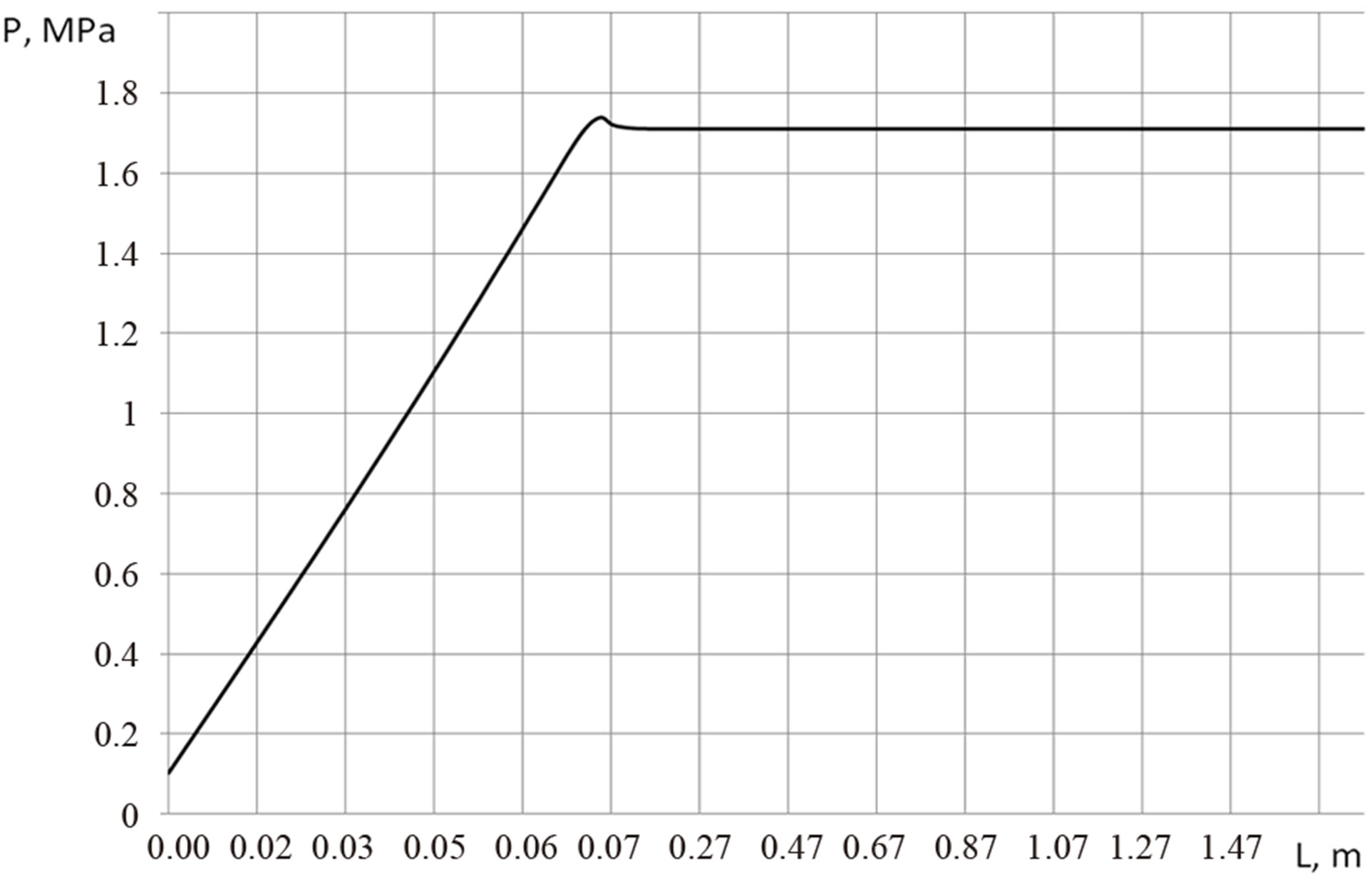
Figure 5. The centerline pressure profile (r = 0).
6) and circumferential (Figure 7) strains in rod section А-А (Figure (1)). It was assumed that external pressure  (Figure 2 (b)), pulling force
  N. In this example the chemical shrinkage was taken as
 , the ultimate strain tension of composite material in according to (15) is
 .
.
To determine the maximum possible pull speed series of solutions at different pull speeds are obtained. For the each of the solution the maximum strains (circumferential and radial) were determined. These values are summarized in Table 1" target="_self"> Table 1. Figure 8 shows the maximum strain profiles as functions of pull speed.
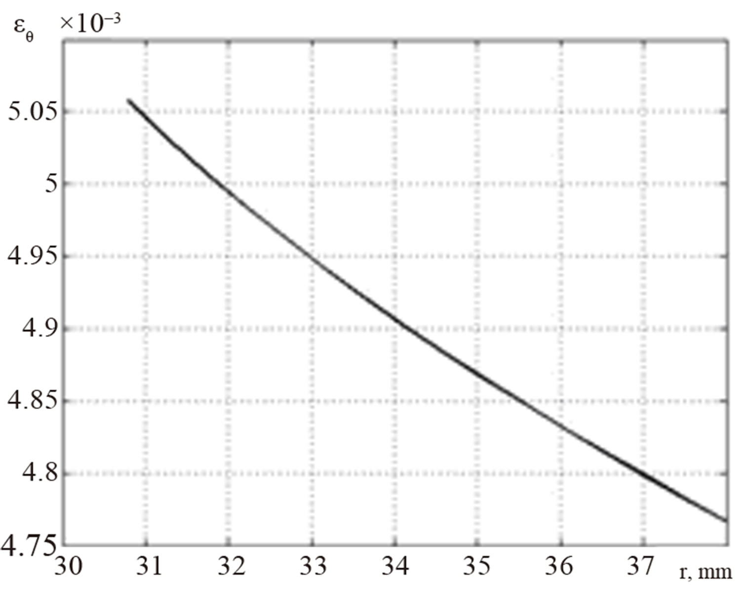
Figure 6. The distribution of radial strains in the cross section.
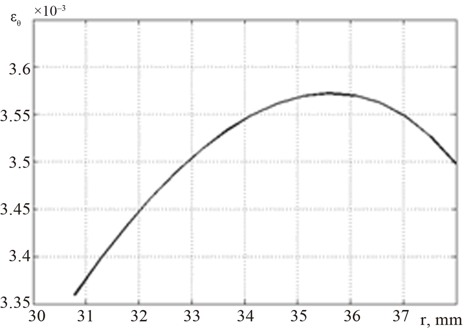
Figure 7. The distribution of circumferential strains in the cross section.
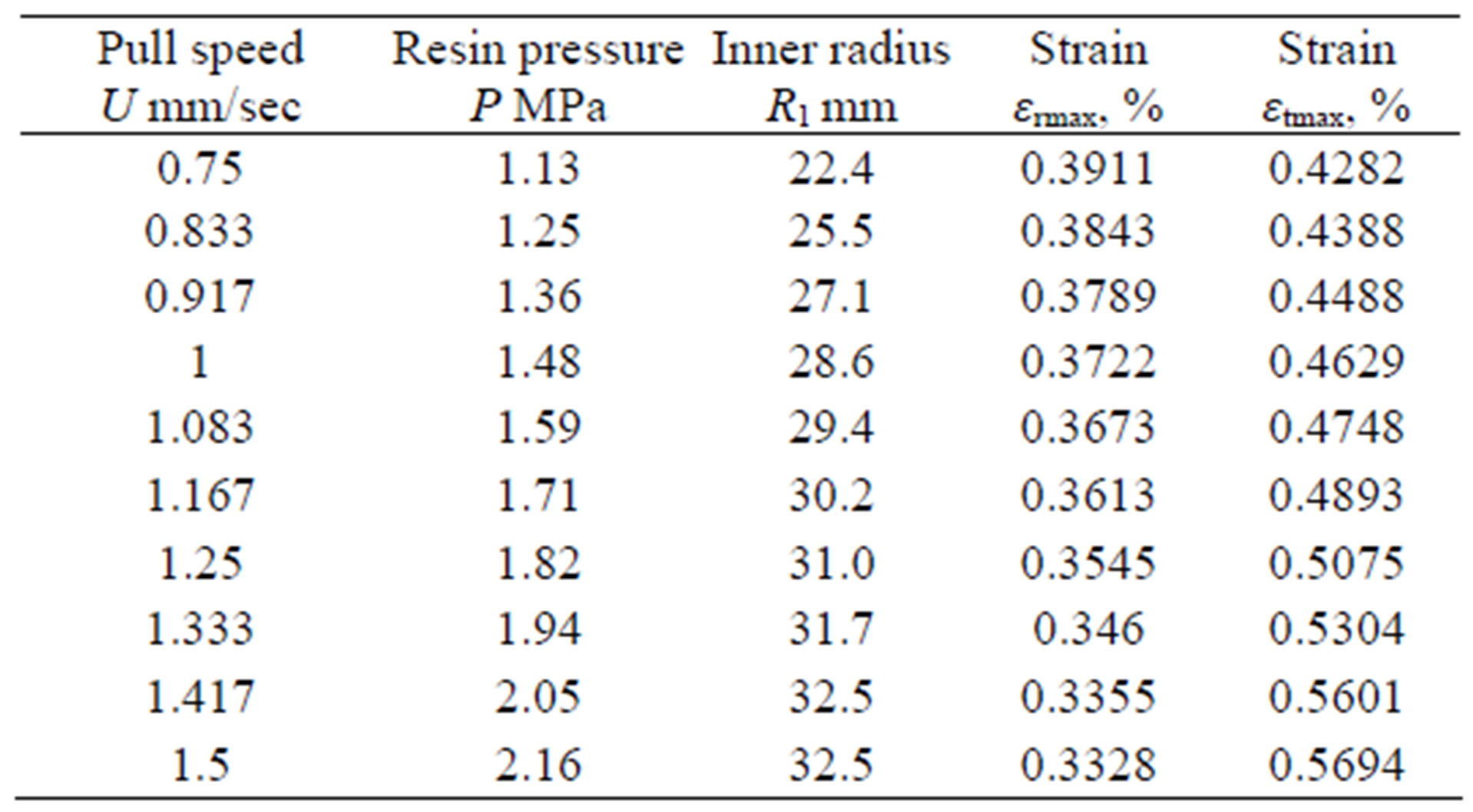
Table 1. Summary results.
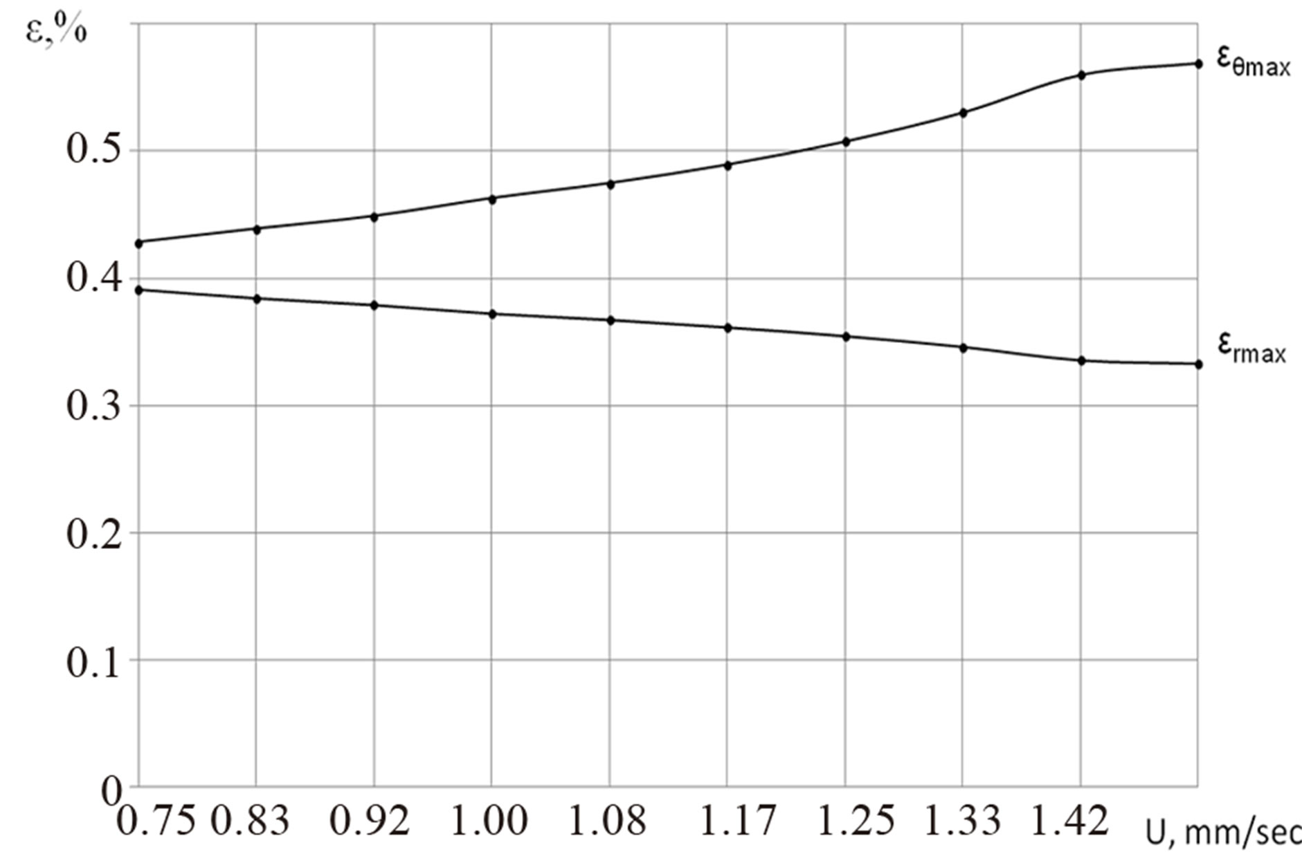
Figure 8. Profiles of the maximum strains as a functions of pull speed.
8. Conclusions
Analyzing the results, it can be concluded that for this example the optimum pull speed is up to 1.33 mm/sec.
The numerical model is a useful tool to determine the stress-strain state of polymer composite materials at the outlet of the Die through the selection of appropriate values for the different process control parameters. An appreciable stress-strain state can help to suppress crack formation, and aid in the manufacture of a quality pultruded product.
REFERENCES
- S. N. Grigoriev, A. N. Krasnovskii and A. R. Khaziev, “Optimum Designing of Long Complicatedly Reinforced Polymeric Composite Structures,” Mechanics of Composite Materials and Structures, Vol. 17, No. 4, 2011, pp. 545-554.
- S. N. Grigoriev, A. N. Krasnovskii and A. R. Khaziev, “Development of Scientific Principles of Technology for Continuous Manufacture of Difficult Reinforced Tubes from Polymeric Composite Materials,” Plastics, Vol. 12, 2011, pp. 56-58.
- S. N. Grigoriev, A. N. Krasnovskii and A. R. Khaziev, “Designing of Composite Anisotropic Rods,” Plastics, No. 1, 2012, pp. 30-32.
- S. N. Grigoriev, A. N. Krasnovskii and A. R. Khaziev, “Mechanics of Pultruded Composite Anisotropic Solid Rod,” Plastics, No. 3, 2012, pp. 18-25.
- S. U. K. Gadam, J. A. Roux, T. A. McCarty and J. G. Vaughan, “The Impact of Pultrusion Processing Parameters on Resin Pressure Rise inside a Tapered Cylindrical Die for Glass-Fibre/Epoxy Composites,” Composites Science and Technology, Vol. 60, No. 6, 2000, pp. 945-958. doi:10.1016/S0266-3538(99)00181-5
- K. S. Raper, J. A. Roux, T. A. McCarty and J. G. Vaughan, “Investigation of the Pressure Behavior in a Pultrusion Die for Graphite/Epoxy Composites,” Composites, Part A: Applied Science and Manufacturing, Vol. 30, No. 9, 1999, pp. 1123-1132. doi:10.1016/S1359-835X(98)00196-1
- B. T. Astrom, “Modeling of Thermoplastic Pultrusion,” 46th Annual Conference, 18-21 February 1991, pp. 1-9.
- V. V. Vasiliev and E. V. Morozov, “Mechanics and Analysis of Composite Materials,” Elsevier Science Ltd., Oxford, 2001.
- A. A. Safonov, “The Mathematical Description of the Polymerization Process in Pultruded Extract,” Problems of Mechanical Engineering and Automation, Vol. 2, 2005, pp. 103-106.
- B. R. Gebart, “Permeability of Unidirectional Reinforcements for RTM,” Journal of Composite Materials, Vol. 26, No. 8, 1992, pp. 1100-1133. doi:10.1177/002199839202600802
- A. A. Samarskii and Е. S. Nikolaev, “Methods for Solving Difference Equations,” The Publishing House “Nauka”, Moscow, 1978.