Positioning
Vol.3 No.4(2012), Article ID:24405,3 pages DOI:10.4236/pos.2012.34006
Research of UAV Flight Planning Parameters
![]()
1Southwest Jiaotong University, GIS Engineering Center, Chengdu, China; 2Engineering Design Co., Ltd., CNPC, Chengdu, China.
Email: xiao00yao@163.com
Received September 2th, 2012; revised October 8th, 2012; accepted October 20th, 2012
Keywords: Unmanned Aerial Vehicles Image; Flight Planning
ABSTRACT
UAV remote sensing as a digital aerial photography, not only has some basic photogrammetry features, but also has some other features. In this paper, aim at the characteristics of UAV remote sensing, begin with image data acquisition, the various parameter setting in the route planning were introduced, some of the principle was analyzed, the design of control points was described, and some of the considerations when laid control points were summarized.
1. Introduction
Unmanned Aerial Vehicles remote sensing technology is an important means of spatial data access, which has advantages of long endurance, real-time image transmission, high-risk areas detection, the low cost, the flexible etc, and complement the technology of satellite remote sensing and manned aerial vehicles remote sensing. Unmanned Aerial Vehicles remote sensing technology countries has been widely used [1,2] in foreign. However, low-altitude digital aerial photography is defined by “Specifications for low-altitude digital aerial photography” issued and implemented by State Bureau of Surveying and Mapping [3] in 2010:
1) Use the light small aircraft, don’t rely on the airport take off and landing;
2) The low relative flight height, commonly below 2000 m;
3) Small format digital camera with above 20 million pixels as the sensor for aerial photogrammetry.
The widely use of domestic UAV aerial photography system marks that the UAV aerial photography system comes to a new age in our country.
However, with the aerial photography system equipment to production unit, it has some phenomenon of field data acquisition quality not qualified. Consequently it leads to the increased difficulties of processing and even is unable to deal with the problem. This paper introduces the low number of aerial photography UAV air route planning, and analysis some specific parameter settings in detail.
2. UAV Images Acquisition
2.1. General Situation of Test Area
Before the flight, it is necessary to collect local meteorological information and the weather conditions. Generally it is good to choose the sunny day without wind. According to the topographic map data and the remote sensing image map information, we learn the terrain information of the test area. If there are mountains, it needs to assess whether the height of the mountains influences flight safety. If there is snow, it needs to access whether the snow influences image quality.
The experimental area located in the hilly region is about 20 km2, and is located in urban and rural area. The height of the highest hills in the test area is about 100 m and has no snow and the elevation is between 490 m and 590 m.
2.2. Flight Parameter Analysis and Settings
The flight parameter including ground sampled distance (GSD), longitudinal overlap degree ( ), side overlap degree (
 ) and some line design related parameters.
UAV fly in the air so fast that adjacent image exposure interval time is short. To ensure that the focal length of the image and other parameters are the same, the camera of UAV takes pictures in the way of the fixed-focus. Focus mode sets in infinity to ensure that it can get the deepest of field range, make the object in the farthest distance and focus distance clear, regardless of short comings of scope of the depth of field.
Ground resolution is the minimum distance to distinguish the two goals in the image, but it doesn’t mean the minimal size to recognize the ground object in the image [4]. For example: a goal with the size of 0.3, in the ground for 0.3 m GSD, is just a pixel, no matter how many times the image zooms in, it is still just a pixel. So, it needs to have several pixels to identify a target in the image. Generally, the smallest size of recognizing target from the image should be the 5 - 10 times of GSD. GSD depends on the focal length, the flight height and pixel size. The pixel size can be written as the following equations (1)-(2):
 (1)
(1)
 (2)
(2)
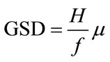
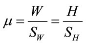
where H is flight height (m), f is focal length (mm), GSD is ground sampled distance (m),  is pixel size (μm), W is the width of CCD (mm), H is the height of CDD(mm), SW is the number of pixels for W, SH is the number of pixels for H.
Due to the use of single spell camera, it can satisfy the largest mapping precision scale for 1:2000 [5]. Figure 1 analysis the geometric relations between the flight height and ground width, where W is ground width, H is flight height. If the camera angle of view is 53˚tan26.5 =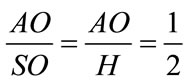 , the flight height H is the ground width of the mages covered. When H increases, the ground width of the mages covered is getting bigger.
Usually, the focal length f,  of the digital camera is fixed. According to equation (1), when H increases, GSD decreases, and from the analysis of the figure 1, it is known that the single image coverage area also increases. Table 1 gives ground coverage area with single digital camera image and the corresponding ground resolution with different flight height for navigation of the view angle of 53˚.
From Table 1 we can see, in the area of certain high, the higher the flight is, the less image pictures we can get. Therefore, after determining the mapping scale, based on
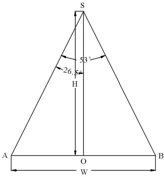
Figure 1. The geometric relations between the flight height and ground width.
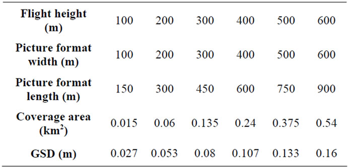
Table 1. Coverage area with single digital camera image.
the principle of the shortened mapping cycle, reducing cost, improving the comprehensive effective of surveying and mapping ,we choose what ground resolution we need. In principle at the beginning, the resolution should not be too high, once we choose the resolution for the ground; we can determine the flight height. Table 2 gives the requirement between the mapping scale and the GSD.
After we determine the GSD and the flight height, we need to set longitudinal overlap degree and side overlap degree, table 3 gives the requirements for the overlap degrees. Because the flight attitude in the air is not stable, the preset overlap degree should be larger. At the same time overlap degree is affected by the weather conditions. The default overlapping degree keeps better effect without wind while the default overlapping degree would be not very good because of the dual action of wind and the shaking and the default overlapping degree will need to raise some. In the experiment the longitudinal overlap degree is 65%, side overlap degree 30%.
The above parameters settings did not consider some special terrain of the surveyed area, such as mountains, the lowlands. Whether the image for these places meets the requirements should do some calculation.
In the terrain of the test, overlap degree of the highest point and the GSD can be calculated as the following equation.
1) Calculation datum elevation
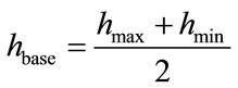 (3)
(3)
where  is the elevation of the highest point,
  is the elevation of the lowest point.
2) Calculation the smallest GSD
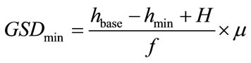 (4)
(4)
where H is the related flight height in design, according to Equation (1) the smallest GSD is the lowest point.
3) Calculation the smallest overlap degree The smallest overlap degree includes longitudinal overlap degree, side overlap degree. It is expressed as the following equation.
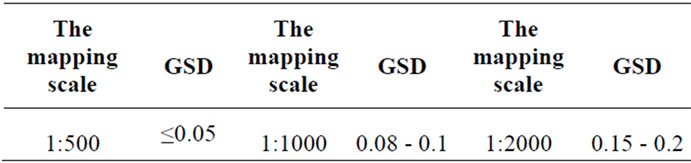
Table 2. GSD.
Table 3. Requirement of overlap degree.
 (5)
(5)
where  is the default longitudinal overlap degree,
  is the default side overlap degree.
  is the smallest default longitudinal overlap degree.
  is the smallest default side overlap degree. According to Equation (5) we can learn that the smallest overlap degree is the highest point in survey area.
When the smallest GSD can not meet the requirement for mapping, or the overlapping degree of the highest point is less than the requirement, GSD should be changed, and the relative flight light, GSD of the lowest point, the overlap degree of the highest point should be calculated once more till it meets the requirements.
2.3. Field Control Points Measurement
The outside directional of an image or stereo can be determined corresponding relation between image and the object space through the geometry transform. To confirm the transform parameter, we need to measure some control point in the image. In order to recognize the control points, the control points logo should be designed carefully, should have the appropriate size and shape, and the contrast between the foreground and background should be high.
In order to ensure that the location of the control points in unmanned aerial vehicle (UAV) flight and measurement process is not moved, we need to mark the location of the four corners for the control points. After flight, when we use RTK to measure the control points. We should check the previous mark and see whether the mark points have been moved. If it has been moved, we should mark notes for remarks in the field measurement. All images control points are measured by RTK. Measurement precision and requirements for the control points is carried out according to “Specifications for aerophotogrammetric office operation of 1:500 1:1000 1:2000 topographic maps” GB/T7930 2008 [6]. All of the control points need to be numbered when measured, and take pictures in the field in order to easily search for prick point in office operation.
In experiment, we come to a conclusion that the marks should not be put on the roadside and the place with too many people, because these control points can be damaged, and even moved easily. We should put it to a relatively empty and hidden place so as to easily find the control points in the UAV image, and also effectively guarantee the safety of the control points marks.
3. Conclusion
With development of the social informatization level ceaselessly, requirements for the speed of obtaining the information become higher and higher. UAVS low-altitude digital aerial photography with the characteristics of its mobile, flexible and efficient just meet the needs of society. In the background that the country promotes the low-altitude photogrammetry UAV development, this paper begins with the data acquisition for low-altitude photography measurements, analyzes flight route planning parameters deeply, optimizes some related parameters combined with requirement the latest promulgated and implemented by the low-altitude digital aerial photography measurement standard, and summarizes some practical attention in operation.
REFERENCES
- P. van Blyenburgh, “UAVs: An Overview,” Air & Space Europe, Vol. 1, No. 5-6, 1999, pp. 43-47.
- J. Sun, Z.-J. Lin and H.-X. Cui, “Low-Altitude UAV Remote Sensing Monitor System,” Remote Sensing Information, Vol. 1, No. 1, 2003, pp. 49-50.
- State Bureau of Surveying and Mapping, “Specifications for Low-Altitude Digital Aerial Photography,” Surveying and Mapping Press, Beijing, 2010.
- D.-Z. Gui, “Study on Construction of 3D Building Based on Wide-Angle and Combine Camera Images from UAV,” China University of Mining and Technology, Xuzhou and Beijing, 2010.
- Z.-J. Lin, “UAV Borne Low Altitude Photogrammetry System,” Science of Surveying and Mapping, Vol. 36, No. 1, 2011, pp. 5-9.
- China National Standardization Management Committee, “Specifications for Aerophotogrammetric Office Operation of 1:500 1:1000 1:2000 Topographic Maps,” China Standards Press, Beijing, 2008.