Journal of Analytical Sciences, Methods and Instrumentation
Vol. 3 No. 1 (2013) , Article ID: 28974 , 7 pages DOI:10.4236/jasmi.2013.31001
Transmission of N-Atoms Produced by N2 Flowing Microwave Afterglows through Hollow Tubes
![]()
Paul Sabatier University, Toulouse, France.
Email: ricard@laplace.univ-tlse.fr
Received November 6th, 2012; revised December 18th, 2012; accepted December 27th, 2012
Keywords: Spectroscopy; N-Atoms Transmission; Hollow Tubes; γ-Destruction Probability
ABSTRACT
Transmission of N-atoms  through small diameters tubes (1.5 and 3 mm internal diameter (i.d) and 9, 50 and 80 cm length for silicone tubes, 1.5 mm i.d and 6.5 cm length for stainless steel tubes) has been measured in late N2 and Ar-N2 flowing afterglows of microwave plasmas in continuous and pulsed gas injection at a flow rate of 1 and 3 Standard liter by minute (Slm), a gas pressure from 2 to 4 Torr for N2 and 20 Torr for Ar-1%N2 and a plasma power from 150 to 300 Watt. From the experimental TN values, it is deduced the γ-destruction probability inside the tube walls as being
  for the silicon tubes and
  for the stainless steel tubes.
1. Introduction
Production of N-atoms has been previously studied in flowing N2 microwave post-discharges at medium gas pressures (1 - 10 Torr) [1]. Bacteria inactivation by Natoms in such post-discharge reactors has been largely studied [1-3]. In these previous papers, it has been obtained a 6 log reduction of an initial bacteria population (E. coli 106 colony forming unit by milliliter, cfu/ml) deposited on planar surfaces with a 40 minutes exposure to a N2 flowing afterglow at 350 K.
In the cited previous works, the N atoms are produced by microwave plasmas at power of 100 - 300 Watt. The plasma is located inside a quartz tube of internal diameter (i.d) 5 mm and extends along a few centimeters outside the cavity (surfatron) gap for a gas pressure between 1 and 30 Torr and a flow rate between 0.5 and 2 Slm.
In these conditions, the plasma gas temperature reached up to 1000 K near the surfatron gap [4], needing an air cooling of the quartz tube. After a few centimetres of post-discharge, it is found the room gas temperature.
After the plasma, early and late afterglows appear and the late afterglow extends in the post-discharge reactor where the sterilization of bacteria is studied.
It is presently reported the results obtained for the transmission of N-atoms produced in the N2 late afterglow through small diameters hollow tubes.
These studies are of interest to appreciate the possibility of N-atoms sterilization inside hollow silicon and stainless steel tubes.
2. The Experimental Setup
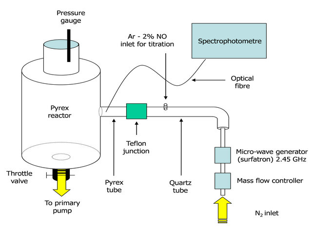
The flowing microwave post-discharge reactor described in previous studies [1-3] is reproduced in Figures 1(a) and (b). A two-stage oil rotary pump with a pumping speed of 48 sm3/h (800 slm) is set up after a 5 litre post-discharge reactor. The N2 flow rate is controlled from 1 to 3 slm. The pressure inside the reactor can be adjusted by means of a throttle valve above the pump (see Figure 1).
A 2.45 Ghz microwave plasma is produced by a surfatron cavity in a quartz tube of 5 mm i.d and 30 cm in length. The discharge tube is connected to a tube of 18 mm i.d and 30 cm in length setup before the 5 litres post-discharge reactor in Pyrex glass. The dia.18 mm tube is in quartz after the dia.5 mm discharge tube and in Pyrex before the 5 litre reactor. A Teflon junction connects the two quartz and Pyrex tubes.
At a pressure of 5 Torr and a flow rate of 1 slm, the flow times are calculated as being  sec and 10−2 sec in the tubes of 5 mm i.d and of 18 mm i.d., respectively.
The emission spectroscopy measurements are performed by moving an optical fibre along the tubes from the plasma gap and the external wall of the post-discharge reactor. The N atom density is obtained by NO titration [4] by injecting an Ar-2%NO gas mixture in the
 (a)
(a)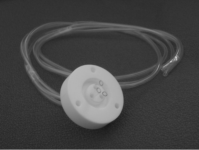 (b)
(b)
Figure 1. Post discharge set up with the emplacement of the Teflon junction connecting the quartz and the Pyrex parts of the 18 mm i.d. tubes (a). The picture shows details of the Teflon junction and the emplacement of the three silicone tubes used in the transmission experiments (b).
post-discharge tube (see Figure 1(a)).
The transmission of N-atoms through hollow tubes was studied by using the Teflon junction allowing to join the quartz and Pyrex parts of the 18 mm i.d. tube Figure 1(b).
Teflon junctions were worked to receive between 3 to 9 tubes of dia. 1 - 3 mm across it.
The insertion of hollow tubes in the Teflon junction produces pressure variations between the plasma tube and the 5 litre reactor.
Such pressure variations were analysed from the afterglow emissions in the 18 mm i.d tube at 2 cm before the Teflon junction (named hereafter z0) by keeping a given pressure in the 5 litre reactor.
The intensity I (580 nm) in z0 versus the gas pressure and for several flow rates is reproduced in Figure 2 without the silicon tubes.
With the silicon tubes, the I (580 nm) intensity in z0 as reported in Figure 2 allows to determine the upstream pressure for a given flow rate.
At a too high N2 pressure ( Torr), it was not always possible to switch on the N2 plasma at a power less than 300 Watt.
Also as described in ref.5 it has been found that the plasma can be switched on at higher pressure by pulsing the gas. For that purpose, a Parker E.M valve was set up between the flow controller and the microwave cavity (see Figure 1)
In such a way the plasma was switched on as the gas pressure decreased when the valve was closed and it was maintained at high pressure when the valve was opened
(at a constant time of  sec).
sec).
An Ar-N2 gas mixture was studied since the plasma is easier to sustain at high pressure [6].
3. Plasmas at High Gas Pressures
3.1. Plasmas in Pulsed N2 Gas
The microwave cavity was first tuned with a continuous gas inlet of 1 slm and an injected power between 100 and 300 Watt. Then by pulsing the gas with a δt pulse varying from 0.1 to 2 sec and a Δt period of 1 and 2 sec, it was successively produced two plasmas at high pressure (2 - 3 Torr) and at low pressure (0.4 - 0.5 Torr) [5].
By checking the  band intensity ratio near the surfatron gap, it was found that the microwave cavity tuning remained with the gas on, as for the continuous case with a negligible reflected power. At low pressure when the gas is off, the reflected power is important, varying from 30 to 90 Watt for an incident power from 100 to 150 Watt [5].
In these conditions, a strong late afterglow of N2 1st pos. bands (with a specific emission at 580 nm, resulting of N+ N atoms recombination) was observed at high pressure and not at low pressure. As discussed in ref.4, the I(580 nm) afterglow intensity at high pressure (>2 Torr) is given by the following equation:
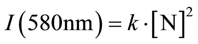 , (1)
, (1)
where k is a constant.
By analysing the time varying gas pressure, afterglow intensity obtained with a photodiode (600 - 900 nm), it is
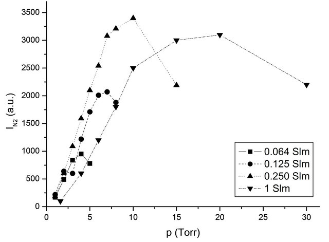
Figure 2. Variation of I (N2, 580 nm) intensity in z0 with N2 gas pressure without the silicon tubes, for several flow rates at 100 Watt.
obtained the results as reproduced in Figure 3.
It was established that for long pulses (0.4 - 1 sec), the N-atom density increased up to the end of gas pulse as did the plasma length A maximum of N-atom density is obtained for time period Δt, twice the pulse time δt. The maximum pressure variations are for long pulses. In the following experimental conditions: incident power 200 Watt, flow rate 1 slm, pump speed 800 slm,  , it is determined a mean N-atom density of
  cm−3 (1015 cm−3 in continuous flow) and a pressure variation
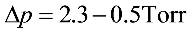 .
.
3.2. Plasmas in Ar-N2 Gas Mixtures
Homogeneous N2 microwave post-discharges can be obtained in the continuous mode at reduced gas pressures (2 - 10 Torr). When the pressure is increased, the plasma became unstable and a 300 W power is not sufficient to sustain the discharge. Adding Ar to N2 allows to obtain a stable discharge from low pressure up to atmospheric gas pressure with N2 percentage below 23% with a microwave power limited to 300 Watt [6].
In the Ar-N2 gas mixtures, the plasma gas temperature was found to be lower than 1000 K. In pure N2 plasma, the electron energy distribution function is depleted above 3 eV because of the low mean vibrational excitation of N2 [7]. In contrast in Ar gas, the first excitation threshold being 11 eV, the extension of electron energy is higher. Consequently, by comparing to pure N2 plasma the ionization in Ar-N2 gas mixture is enhanced particularly at low N2 percentage.
4. Transmission of N-Atoms in Hollow Tubes
4.1. Silicone Tubes
It was first experimented 9 tubes of silicones of int.dia. (i.d) 1.5 mm and out.dia. (o.d) 2 mm located inside the Teflon junction of Figure 1 where 9 holes of dia. 2 mm were made inside a Teflon tap.
When the length of the tubes was 150 cm, it was necessary to pulse the gas with  at 200 Watt to switch on the N2 plasma (see 3.1). In continuous mode, it was not possible to produce the N2 plasma at 300 Watt.
In these pulsed conditions the afterglow with mainly emission of N2 (580 nm) extended up to 50 cm inside the 9 tubes.
The length of the tubes was then reduced to 50 cm and the afterglow was detected inside the 5 litre reactor.
In conditions of , 200 Watt, 1 slm, the gas pressure was found varying from 0.8 to 2.0 Torr in the 5 litre reactor and the N-atom density was obtained from the I(580 nm) intensity (see Equation (1)) after caliP (Torr)

T (sec)
Figure 3. Variations with time of gas pressure (1) in Torr, of photodiode signal (2) and of electric field of the EM valve (3), obtained by the labview program. The photodiode and electric field signals are in arbitrary units. 150 Watt, 1 slm,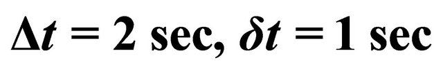 .
.
bration by NO titration [1-4].
It was found  at 1 cm before the Teflon junction. In the 5 litre reactor, the N-atom density was evaluated from the I (580 nm) intensity, corrected from the change of optical thickness between the Pyrex tube and reactor chamber. It was deduced
 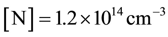 after 50 cm of silicon tubes length. The N-atom transmission TN was thus evaluated to 3.5%.
A second experiment was undertaken with a Teflon tap bored of 3 holes of dia. 4 mm connecting 3 silicon tubes of i.d. 3 mm and o.d. 4 mm, of length from 80 to 250 cm.
For these larger diameter tubes, the N2 plasma was switched on in the continuous mode.
At a flow rate of 1 Slm, a pressure of 4 Torr in the 5 litre reactor, a power of 150 Watt and silicon tube lengths of 80 cm, it is determined a N-atom density of  cm−3 before the Teflon tap and
  in the 5 litre reactor.
At a low flow rate of 125 Sccm, a power of 100 Watt and silicon tube lengths of 60 cm, it was obtained a slow increase of TN from 3.9% at 1 Torr to 4.9% at 3 Torr.
To improve the plasma lighting at high flow rate thus at high gas pressure, it was experimented as discussed in 3 - 2, an Ar-1%N2 gas mixture.
Then the plasma was obtained in continuous mode at 150W, 3slm, 20 Torr and length 80 cm of the silicon tubes. The N-atom density before the Teflon tap was found to be  cm−3 and
  at 80 cmthat is an increase of 3 of N-atom density and the same TN value in comparison to N2 150 W, 1 slm.
4.2. Stainless Tubes
9 stainless tubes of i.d 1.5 mm and o.d 2 mm, of length 6.5 cm was located across the tap of the Teflon junction as for the silicon tubes in the 1st experiment in 4.1.
A continuous N2 plasma was obtained at 300 W, 1 slm and 1.7 Torr in the 5 litre reactor. In these conditions, the N atom density was  cm−3 at z0, before the Teflon junction and decreased sharply to about 1014 cm−3 at the exit of the 9 stainless tubes of length 6.5 cm, that is an N-atom transmission of 1.3%.
In the pulse mode , 200 Watt, 1 slm, gas pressure varying from 0.9 to 2.3 Torr, the N-atom transmission was increased to 3.5% - 4%.
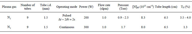
The TN transmission through silicone tubes of int. dia. 1.5 and 3 mm and various lengths of 9, 10 and 80 cm in pulsed and continuous N2 plasmas are reported in Table 1(a). The result obtained with a continuous Ar-1%N2 plasma is also reported. In Table 1(b), it is reported the TN values through stainless tubes of int.dia 1.5 mm and length 6.5 cm in pulsed and continuous N2 plasmas.
4.3. γ-Probability of N-Atom Destruction on the Tube Walls
By estimating that the main loss of N-atoms is by colli-
Table 1. Transmission of N-atoms through: (a) Silicone tubes of int. dia. 1.5 and 3 mm and various lengths of 9, 10 and 80 cm.Pulsed and continuous N2 plasmas. Continuous Ar-1%N2 plasmas; (b) Stainless tubes of int.dia 1.5 mm and length 6.5 cm. Pulsed and continuous N2 plasmas.
(a) Silicone tubes

(b) Stainless steel tubes
sions on tube wall, it is written:
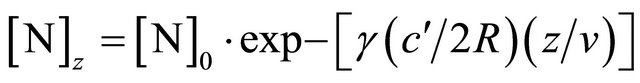 (2)
(2)
where z is the axial distance in the silicon tube, [N]0 is the N-atom density at z0,  is the thermal gas velocity at 300K:
 , R is the tube radius and v the axial gas velocity.
The axial gas velocity is deduced from the flow rate Q by:
 (3)
(3)
where  is the flow rate at pressure
  , Q0 is the standard flow rate (760 Torr, 300K) and S is the tube internal surface.
To obtain a nearly constant gas pressure in the 3 silicon tubes, the flow rate was decreased to 0.125 Slm for a pressure of 1 - 3 Torr in the 5 litre reactor.
At , the I (580 nm) measured in z0 with the silicon tubes at 2 Torr indicates a pressure before the Teflon junction of 2 - 3 Torr.
With Equation (3), it is calculated at 2 Torr an axial gas velocity of  cm·sec−1 corresponding to a flow time in the silicon tubes of
  s at 60 cm.
Then, it is determined from Equations (2) and (3), a γ value varying from 1.2 to  as the pressure in the reactor increased from 1 to 3 Torr.
Such values are 3 times lower than published values for Nylon [8]:  at 2 - 3 Torr.
The γ-value has been calculated with the Ar-1%N2 gas mixture in conditions of 3 slm and 20 Torr in the 5 litre reactor. From the I(580 nm) intensity calibrated with the Ar-1%N2 gas mixture as for N2 in Figure 2, it is estimated a pressure of 45 Torr in front the Teflon tape. By taking the mean value of pressure pm= 32 Torr in the tubes, it is calculated from Equation (3) an axial velocity of  cm·s−1. At 80 cm, it is measured TN = 8.5%. It is then calculated from Equation (1) that
 .
.
In N2, 1 slm, 150 Watt, the pressure before the Teflon tape is found from Figure 2 to be 10 Torr. For a pressure of 4 Torr in the 5 litre reactor, the mean pressure in the tubes is 7 Torr, the axial velocity is  cm·s−1. With TN = 8.5% at 80 cm, it is deduced
  near the published value for Nylon at 4 Torr:
  [8].
[8].
It is concluded to about the same value of γ probability of N atoms in pure N2 and in the Ar-1%N2 gas mixture: . The argon gas has no influence on the N-atom destruction probability on the silicon tubes walls.
With such γ values, it can be calculated the N-atom density at the exit of the 3 silicon tubes of i.d. 3 mm and length 250 cm:  cm−3 for N2 at 1 Slm, 150 W and 4Torr in the 5 litre reactor and
  cm−3 for Ar-1% N2 at 3 Slm, 150 W and 20 Torr. The increase of N-atoms density by 4.4 when N2 is changed into the Ar-1%N2 gas mixture comes from the increases by a factor 3 of N-atom density before the Teflon tape and by a factor 3 of flow rates in spite of increase of pressure in the tubes of length 250 cm from about 20 Torr in N2 to 30 Torr in Ar-1%N2.
Equations (2) and (3) are applied to the results of the stainless tubes in part 4.2.
The pressure before the tap of the 9 stainless tubes was determined from the I (580 nm) intensity as it has been experimented with the silicon tubes. It is estimated a pressure of 10 - 16 Torr for 4 Torr in the 5 litre reactor. The mean pressure in the tubes is taken between 7 - 10 Torr.
With a N-atom transmission of 1.3% in continuous mode after 6.5 cm of tube length, it is calculated .
.
This value is 3 - 4 times higher than the published values in pulsed RF discharge for stainless steel [9]:  at 5 Torr and
  at 3 Torr.
5. Conclusions
Transmission of N-atoms through hollow tubes in the late flowing afterglow of a N2 microwave discharge has been measured for silicon tubes of i.d. 3 mm and a length up to 250 cm and for stainless steel tubes of i.d 1.5 mm and 6.5 cm length. The hollow tubes were placed though holes in a Teflon tap across a Teflon junction of i.d.18 mm in the main N2 flow before a 5 litre reactor. Depending on the gas flow, a gas pressure variation is produced before and after the Teflon junction. To switch on the plasma at high gas pressure, it was experimented pulsed N2 gas modes and Ar-N2 gas mixtures. The pulse gas mode was of interest to produce the plasma at lower gas pressure when the gas was off and to maintain it at high pressure when the gas was on.
In comparison to continuous discharges, the N-atom transmission across the 1.5 mm i.d stainless steel tubes increased with the pulsed gas mode.
An Ar-1%N2 gas mixture has allowed to produce plasmas at high flow rates and gas pressures with higher N-atom density than in pure N2.
The γ-destruction probability has been determined inside the tube walls as being 
10−3 for the silicon tubes and  for the stainless steel tubes. The γ-values are in good agreement with published values for the silicon tubes but not for the stainless steel tubes which appear to be 3 - 4 times higher.
With a value , the best result for N-atom injection in the silicon tubes of 3 mm i.d and length 250 cm is obtained with an Ar-1%N2 gas mixture at 3 Slm, 150 W giving a measured density of
  cm−3 before and a calculated density of
  cm−3 after the tubes in the 5 litre reactor.
6. Acknowledgments
Thanks to the Acteon-Satelec company (Mérignac-France) to have supported the research on N2 plasma—post-discharge sterilization.
REFERENCES
- S. Villeger, J. P. Sarrette and A. Ricard, “Synergy between N and O Atom Action and Substrate Surface Temperature in a Sterilization Process Using a Flowing N2-O2 Microwave Post Discharge,” Plasma Processes and Polymers, Vol. 2, No. 9, 2005, pp. 709-714. doi:10.1002/ppap.200500040
- S. Villeger, S. Cousty, A. Ricard and M. Sixou, “Sterilization of E. coli Bacterium in a Flowing N2-O2 PostDischarge Reactor,” Journal of Physics D: Applied Physics, Vol. 36, No. 13, 2003, pp. L60-L62.
- S. Villeger, J. P. Sarrette, B. Rouffet, S. Cousty and A. Ricard, “Treatment of Flat and Hollow Substrates by a Pure Nitrogen Flowing Post Discharge,” The European Physical Journal Applied Physics, Vol. 42, No. 1, 2008, pp. 25-32. doi:10.1051/epjap:2007177
- P. Merel, M. Tabbal, M. Chaker, M. Moisan and A. Ricard, “Influence of the Field Frequency on the Nitrogen Atom Yield in the Remote Plasma of an N2 High Frequency Discharge,” Plasma Sources Science and Technology, Vol. 7, No. 4, 1998, p. 550. doi:10.1088/0963-0252/7/4/012
- A. Ricard, F. Moser, S. Cousty, S. Villeger and J. P. Sarrette, “Time Varying Afterglow Emission and Gas Pressure in a Pulsed N2 Gas Microwave Flowing Discharge at Reduced Pressure,” The European Physical Journal Applied Physics, Vol. 49, No. 1, 2010, pp. 13104-13107. doi:10.1051/epjap/2009195
- A. Ricard, F. Gaboriau and C. Canal, “Optical Spectroscopy to Control a Plasma Reactor for Surface Treatments,” Surface and Coatings Technology, Vol. 202, No. 22-23, 2008, pp. 5220-5224. doi:10.1016/j.surfcoat.2008.06.070
- M. Capitelli (Ed.), “Non-Equilibrium Vibrational Kinetics, Topics in Current Physics Volume 56,” Springer, Berlin, 1986.
- J.-P. Sarrette, B. Rouffet and A. Ricard, “Determination of Nitrogen Atoms Loss Probabilities on Copper, Aluminium, Alumina, Brass and Nylon Surfaces,” Plasma Processes and Polymers, Vol. 3, No. 2, 2006, pp. 120- 126. doi:10.1002/ppap.200500113
- S. F. Adams and T. A. Miller, “Surface and Volume Loss of Atomic Nitrogen in a Parallel Plate of Discharge Reactor,” Plasma Sources Science and Technology, Vol. 9, No. 3, 2000, p. 248. doi:10.1088/0963-0252/9/3/302